1
HEG
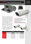
Large-sized camera housing
EN English - Instructions manual
IT Italiano - Manuale di istruzioni
FR Français - Manuel d’instructions
DE Deutsch - Bedienungslanleitung
RU Русский - Руководство по эксплуатации
HEG
Large-sized camera housing
EN English - Instructions manual
Contents
ENGLISH
1 About this manual.......................................................................................................... 3
1.1 Typographical conventions................................................................................................................................... 3
2 Notes on copyright and information on trademarks................................................... 3
3 Safety rules..................................................................................................................... 3
4 Identification................................................................................................................... 4
4.1 Product description and type designation..................................................................................................... 4
4.2 Product markings..................................................................................................................................................... 4
5 Preparing the product for use....................................................................................... 4
5.1 Safety precautions before use.............................................................................................................................. 4
5.2 Unpacking and contents........................................................................................................................................ 4
5.2.1 Unpacking................................................................................................................................................................................... 4
5.2.2 Contents....................................................................................................................................................................................... 4
5.3 Safely disposing of packaging material............................................................................................................ 4
5.4 Preparatory work before installation................................................................................................................. 4
5.4.1 Attaching the bracket............................................................................................................................................................. 4
6 Assembling and installing............................................................................................. 5
6.1 Installation................................................................................................................................................................... 5
6.1.1 How to open the housing...................................................................................................................................................... 5
6.1.2 How to install the camera...................................................................................................................................................... 5
6.1.3 Board description..................................................................................................................................................................... 6
6.1.4 Connection of the power supply line................................................................................................................................ 6
6.1.4.1 Type of cable.................................................................................................................................................................................................... 6
6.1.5 Installation of the version with double filter for air renewal..................................................................................... 7
6.1.6 Desiccant bag............................................................................................................................................................................ 7
7 Accessories...................................................................................................................... 7
7.1 Heater............................................................................................................................................................................ 7
7.1.1 Heater installation.................................................................................................................................................................... 7
7.2 Camera power supply............................................................................................................................................. 7
7.2.1 Camera power supply installation...................................................................................................................................... 7
8 Instructions for normal operation................................................................................. 8
9 Maintaining and cleaning.............................................................................................. 8
9.1 Cleaning....................................................................................................................................................................... 8
9.1.1 Window and plastic cover cleaning................................................................................................................................... 8
10 Disposal of waste materials......................................................................................... 8
11 Technical data............................................................................................................... 9
11.1 General....................................................................................................................................................................... 9
11.2 Mechanical................................................................................................................................................................ 9
11.3 Electrical.................................................................................................................................................................... 9
11.4 Environment............................................................................................................................................................ 9
11.5 Certifications............................................................................................................................................................ 9
12 Technical drawings..................................................................................................... 10
1 About this manual
1.1 Typographical conventions
DANGER!
High level hazard.
Risk of electric shock. Disconnect the power
supply before proceeding with any operation,
unless indicated otherwise.
CAUTION!
Medium level hazard.
This operation is very important for the
system to function properly. Please read the
procedure described very carefully and carry
it out as instructed.
INFO
Description of system specifications.
We recommend reading this part carefully in
order to understand the subsequent stages.
2 Notes on copyright and
information on trademarks
The quoted names of products or companies are
trademarks or registered trademarks.
MNVCHEG_1511_EN
CAUTION! The device must be installed
only and exclusively by qualified technical
personnel.
• The manufacturer declines all responsibility
for any damage caused by an improper use
of the appliances mentioned in this manual.
Furthermore, the manufacturer reserves the right
to modify its contents without any prior notice.
The documentation contained in this manual has
been collected with great care. The manufacturer,
however, cannot take any liability for its use. The
same thing can be said for any person or company
involved in the creation and production of this
manual.
• Before starting any operation, make sure the
power supply is disconnected.
• Do not use cables that seem worn or old.
• Never, under any circumstances, make any
changes or connections that are not shown in
this handbook. Improper use of the appliance
can cause serious hazards, risking the safety of
personnel and of the installation.
• Use only original spare parts. Non-original spare
parts could cause fire, electrical discharge or other
hazards.
• Before proceeding with installation, check the
supplied material to make sure it corresponds
to the order specification by examining the
identification labels (4.2 Product markings, page 4).
3
Instructions manual - English - EN
Before installing and using this unit, please read this
manual carefully. Be sure to keep it handy for later
reference.
3 Safety rules
EN - English - Instructions manual 4 Identification
5.2 Unpacking and contents
4.1 Product description and type
designation
5.2.1 Unpacking
Robust and large aluminum housing designed to fit
1/2", 1/3" and 1/4"cameras with optics of different
kinds.
It can be used for a variety of applications, for the
monitoring of urban and highways, in particular if
coupled with the PTH900 P&T series .
The opening system allows an easy access for
installation and servicing.
It can be installed with cable sheaths, instead of
regular cable glands using the junction box for the
wiring harness.
A wide range of accessories for mounting the
equipment is available thereby satisfying all
installation needs.
When the product is delivered, make sure that the
package is intact and that there are no signs that it
has been dropped or scratched.
If there are obvious signs of damage, contact the
supplier immediately.
Keep the packaging in case you need to send the
product for repairs.
5.2.2 Contents
Check the contents to make sure they correspond
with the list of materials as below:
• Housing
• Housing equipment:
• Allen wrenches
• Spacers
• Bolts and screws
4.2 Product markings
• Desiccant bag
See the label attached to the product.
• Instructions manual
5 Preparing the product for
use
5.3 Safely disposing of packaging
material
Any change that is not expressly approved
by the manufacturer will invalidate the
guarantee.
5.1 Safety precautions before use
CAUTION! The electrical system to which the
unit is connected must be equipped with a
15A max automatic bipolar circuit breaker.
The minimum distance between the contacts
must be 3mm (0.1in). The circuit breaker must
be provided with protection against the fault
current towards the ground (differential) and
the overcurrent (magnetothermal).
4
The packaging material can all be recycled. The
installer technician will be responsible for separating
the material for disposal, and in any case for
compliance with the legislation in force where the
device is to be used.
When returning a faulty product we recommend
using the original packaging for shipping.
5.4 Preparatory work before
installation
5.4.1 Attaching the bracket
The product must be fastened with suitable
equipment. The fastening means must
guarantee the mechanical seal when a force
equal to at least 4 times the weight of the
device is applied.
MNVCHEG_1511_EN
6 Assembling and installing
6.1.2 How to install the camera
6.1 Installation
6.1.1 How to open the housing
Unscrew the screws on the rear cover plate and
loosen the 2 dowels on the outer slide. Slide out the
housing body.
Open the housing as described previously (6.1.1 How
to open the housing, page 5).
Fasten the camera with the 1/4" screw (01). To
position the camera and lens correctly, if necessary,
use the supplied spacers. (02).
02
01
Fig. 2
Fig. 1
At the end of istallation and cabling
operations close the housing.
Remove the conductors protective sheathing and
connect them to terminal (camera power supply,
6.1.3 Board description, page 6).
The camera’s power supply cable conductors must be
tied up with a cable tie next to the terminal. Keep the
signalling and power supply cables separated from
each other.
Reposition the internal slide and tighten the screws
that had been loosened previously.
MNVCHEG_1511_EN
5
Instructions manual - English - EN
Power supply can be provided by the board
supplied with the product. Make sure the
voltage values are appropriate.
The assembly and installation must be
performed only by skilled personnel.
6.1.3 Board description
EN - English - Instructions manual Connect the safety earth to the relative
terminal of the power supply connector.
The board may appear different to that
illustrated.
Depending on the product version, the board
may not be equipped with all functions.
Insert the cables for the connection to the power
supply line inside the housing through the cable
glands. The cable glands are suitable for conductors
with diameters of between 5mm and 10mm. The
section of the cable inside the housing must be
sufficiently long to allow connection. Suitably lock
the cable glands.
6.1.4.1 Type of cable
BOARD DESCRIPTION
Connector
6.1.4 Connection of the power supply
line
Function
J1
Camera power supply (VOUT )1
J2
Heater power supply (VOUT )
J3
Board power supply (VIN)2
J4
Auxiliary output (VOUT )3
J5
Power supply connector/jumper4
J6
Fan power supply (VOUT )
Tab. 1
Different alternatives are available depending on the
version. VOUT = 12Vdc o VOUT = 24Vac, in relation to the
type of power supply installed (7.2.1 Camera power
supply installation, page 7). VOUT = VIN, only for housings
powered in 12Vdc or 24Vac, with jumper inserted (J5).
2
3
4
The cable used for the connection to the power
supply line must be suitable for the intended use.
Comply with the current national standards on
electrical installations.
1
From 100Vac a 240Vac, 24Vac o12Vdc.
Same voltage applied to power supply terminal of the
board (J3).
To install a power supply in 12Vdc or 24Vac refer to the
relative chapter (7.2.1 Camera power supply installation, page 7).
J6
J5
J1
J3
J4
J2
Fig. 3
6
MNVCHEG_1511_EN
6.1.5 Installation of the version with
double filter for air renewal
For further details on configuration and use,
refer to the relative manual.
Instructions manual - English - EN
During installation pay attention to the
orientation of the air inlet filter fins.
7 Accessories
7.1 Heater
7.1.1 Heater installation
At the end of istallation, connect the wiring to
the terminal (heater power supply, 6.1.3 Board
description, page 6).
OUT
7.2 Camera power supply
7.2.1 Camera power supply installation
Not usable in housings with wiper device
installed.
Fig. 4
To guarantee the weatherproof, install the housing
on the support following the inclination limits as
shown in the picture.
Depending on the angle of inclination of the housing,
the orientation of the filter fins must prevent water
penetrating in case of rain:
Pay attention to the voltage value used
when the circuit is powered. Depending on
requirements use the correct power supply
kit.
There are 2 types of camera power supply depending
on requirements.
45°
45°
0˚
Fig. 6VIN from 100Vac a 240Vac, VOUT 12Vdc.
Fig. 7VIN 230Vac, VOUT 24Vac.
Fig. 5
Maximum tilt of the transversal axis: 0°.
Maximum tilt of the longitudinal axis: ±45°.
At the end of istallation, connect the wiring to the
terminal (power supply connector, 6.1.3 Board
description, page 6).
6.1.6 Desiccant bag
Take the dessicant salt bag out of its pack and insert it
into the product.
MNVCHEG_1511_EN
7
EN - English - Instructions manual 8 Instructions for normal
operation
Do not use the wiper when the outside
temperature is below 0°C or in case of ice.
9 Maintaining and cleaning
Before doing any technical work on the
device, disconnect the power supply.
9.1 Cleaning
9.1.1 Window and plastic cover cleaning
Avoid ethyl alcohol, solvents, hydrogenated
hydrocarbide, strong acid and alkali. Such
products may irreparably damage the
surface.
10 Disposal of waste
materials
This symbol mark and recycle system are
applied only to EU countries and not applied
to the countries in the other area of the
world.
Your product is designed and manufactured with
high quality materials and components which can be
recycled and reused.
This symbol means that electrical and electronic
equipment, at their end-of-life, should be disposed of
separately from your household waste.
Please dispose of this equipment at your local
Community waste collection or Recycling centre.
In the European Union there are separate collection
systems for used electrical and electronic products.
We recommend using a soft cloth with neutral soaps
diluted with water or specific products to clean the
glasses lenses.
8
MNVCHEG_1511_EN
11 Technical data
Constructed from aluminium
Epoxypolyester powder painting, RAL9002 colour
Stainless steel external screws
11.2 Mechanical
Cable glands: 3xM16
Housing window
• Dimensions (WxH): 94x80mm (3.7x3.1in)
• Material: Glass
Internal usable area
• Empty version: 134x88mm (5.1x3.5in)
• Version with double or triple heater : 112x88mm
(in)
Internal usable length (without accessories)
• HEG37: 365mm (in)
• HEG47: 450mm (in)
Internal usable length (with accessories):
• HEG37: 273mm (10.7in)
• HEG47: 363mm (in)
Unit weight
• HEG37: 4.1kg (9lb)
• HEG47: 4.7kg (10.3lb)
Instructions manual - English - EN
11.1 General
Power supply/Current consumption (version with
triple heater, continuous duty fan , Ton 15°C±3°C
(59°F ±5°F), Toff 22°C±3°C (77°F±5°F)):
• 120Vac, 1A max, 50/60Hz
• 230Vac, 0.52A max, 50/60Hz
Power supply/Current consumption (version with
blower and thermostat for models with double
filter for air renewal, Ton 35°C±3°C (95°F±5°F), Toff
20°C±3°C (71°F±5°F)):
• 12Vdc, 0.33A max
• 24Vac, 0.16A max, 50/60Hz
Camera power supply:
• VIN from 100Vac a 240Vac, 50/60Hz
VOUT 12Vdc, 1A
• VIN 230Vac, 50/60Hz
VOUT 24Vac, 400mA, 50/60Hz
11.4 Environment
Indoor/Outdoor
Operating temperature
• Version with heater: From -20°C (-4°F) a +60°C
(140°F)
• Version with double heater: From -40°C (-40°F) a
+60°C (140°F)
• Version with triple heater, continuous duty fan:
From -50°C (-58°F) a +60°C (140°F)
11.5 Certifications
11.3 Electrical
Electrical safety (CE): EN60065
Power supply/Current consumption (version with
heater, Ton 15°C±3°C (59°F ±5°F), Toff 22°C±3°C
(77°F±5°F)):
Electromagnetic compatibility (CE): EN50130-4,
EN61000-6-3
IP protection degree:
• 12Vdc, 1.6A max
• EN60529, IP66/IP67 (with cable glands)
• 24Vac, 0.85A max, 50/60Hz
• EN60529, IP44 (with double filter for air renewal)
• 120Vac, 0.35A max, 50/60Hz
Salty fog resistance: ISO9227, to 1000 hours
• 230Vac, 0.18A max, 50/60Hz
EAC certification
Power supply/Current consumption (version with
double heater, Ton 15°C±3°C (59°F ±5°F), Toff
22°C±3°C (77°F±5°F)):
• 120Vac, 0.7A max, 50/60Hz
• 230Vac, 0.35A max, 50/60Hz
MNVCHEG_1511_EN
9
12 Technical drawings
The dimensions of the drawings are in millimetres.
175
42
153
365 / 450
32
273 / 363
A
168
141
USABLE AREA
A-A
A
88
134
112
493 / 590
B
USABLE
AREA
B-B
B
Fig. 8HEG.
Headquarters Italy Videotec S.p.A.
France Videotec France SARL
Asia Pacific Videotec (HK) Ltd
Americas Videotec Security, Inc.
Via Friuli, 6 - I-36015 Schio (VI) - Italy
Tel. +39 0445 697411 - Fax +39 0445 697414
Email: [email protected]
Flat 8, 19/F. On Dak Industrial Building, No. 2-6 Wah Sing Street
Kwai Chung, New Territories - Hong Kong
Tel. +852 2333 0601 - Fax +852 2311 0026
Email: [email protected]
Immeuble Le Montreal, 19bis Avenue du Québec, ZA de Courtaboeuf
91140 Villebon sur Yvette - France
Tel. +33 1 60491816 - Fax +33 1 69284736
Email: [email protected]
Gateway Industrial Park, 35 Gateway Drive, Suite 100
Plattsburgh, NY 12901 - U.S.A.
Tel. +1 518 825 0020 - Fax +1 518 825 0022
Email: [email protected] - www.videotec.us
www.videotec.com
MNVCHEG_1511_EN
HEG
Custodia per telecamera di grandi dimensioni
IT Italiano - Manuale di istruzioni
Sommario
ITALIANO
1 Informazioni sul presente manuale.............................................................................. 3
1.1 Convenzioni tipografiche...................................................................................................................................... 3
2 Note sul copyright e informazioni sui marchi commerciali......................................... 3
3 Norme di sicurezza......................................................................................................... 3
4 Identificazione................................................................................................................ 4
4.1 Descrizione e designazione del prodotto........................................................................................................ 4
4.2 Marcatura del prodotto.......................................................................................................................................... 4
5 Preparazione del prodotto per l'utilizzo....................................................................... 4
5.1 Precauzioni di sicurezza prima dell'utilizzo..................................................................................................... 4
5.2 Disimballaggio e contenuto................................................................................................................................. 4
5.2.1 Disimballaggio........................................................................................................................................................................... 4
5.2.2 Contenuto................................................................................................................................................................................... 4
5.3 Smaltimento in sicurezza dei materiali di imballaggio............................................................................... 4
5.4 Lavoro preparatorio prima dell’installazione.................................................................................................. 4
5.4.1 Fissaggio del supporto........................................................................................................................................................... 4
6 Assemblaggio e installazione........................................................................................ 5
6.1 Installazione................................................................................................................................................................ 5
6.1.1 Apertura della custodia.......................................................................................................................................................... 5
6.1.2 Installazione della telecamera............................................................................................................................................. 5
6.1.3 Descrizione della scheda....................................................................................................................................................... 6
6.1.4 Collegamento della linea di alimentazione.................................................................................................................... 6
6.1.4.1 Tipo di cavo...................................................................................................................................................................................................... 6
6.1.5 Installazione della versione con doppio filtro per ricambio dell'aria..................................................................... 7
6.1.6 Sacchetto disidratante............................................................................................................................................................ 7
7 Accessori.......................................................................................................................... 7
7.1 Riscaldamento........................................................................................................................................................... 7
7.1.1 Installazione del riscaldamento.......................................................................................................................................... 7
7.2 Alimentatore per telecamera............................................................................................................................... 7
7.2.1 Installazione dell’alimentatore per telecamera............................................................................................................. 7
8 Istruzioni di funzionamento ordinario......................................................................... 8
9 Manutenzione e pulizia.................................................................................................. 8
9.1 Pulizia............................................................................................................................................................................ 8
9.1.1 Pulizia del vetro e delle parti in plastica........................................................................................................................... 8
10 Smaltimento dei rifiuti................................................................................................. 8
11 Dati tecnici.................................................................................................................... 9
11.1 Generale.................................................................................................................................................................... 9
11.2 Meccanica................................................................................................................................................................. 9
11.3 Elettrico...................................................................................................................................................................... 9
11.4 Ambiente................................................................................................................................................................... 9
11.5 Certificazioni............................................................................................................................................................ 9
12 Disegni tecnici............................................................................................................ 10
Prima di installare e utilizzare questa unità, leggere
attentamente questo manuale. Conservare questo
manuale a portata di mano come riferimento futuro.
1.1 Convenzioni tipografiche
PERICOLO!
Pericolosità elevata.
Rischio di scosse elettriche. Prima di
eseguire qualsiasi operazione assicurarsi di
togliere tensione al prodotto, salvo diversa
indicazione.
ATTENZIONE!
Pericolosità media.
L'operazione è molto importante per il
corretto funzionamento del sistema. Si
prega di leggere attentamente la procedura
indicata e di eseguirla secondo le modalità
previste.
INFO
Descrizione delle caratteristiche del sistema.
Si consiglia di leggere attentamente per
comprendere le fasi successive.
2 Note sul copyright e
informazioni sui marchi
commerciali
I nomi di prodotto o di aziende citati sono marchi
commerciali o marchi commerciali registrati
appartenenti alle rispettive società.
MNVCHEG_1511_IT
3 Norme di sicurezza
ATTENZIONE! L'installazione e la
manutenzione del dispositivo deve
essere eseguita solo da personale tecnico
qualificato.
• Il produttore declina ogni responsabilità per
eventuali danni derivanti da un uso improprio
delle apparecchiature menzionate in questo
manuale. Si riserva inoltre il diritto di modificarne il
contenuto senza preavviso. Ogni cura è stata posta
nella raccolta e nella verifica della documentazione
contenuta in questo manuale. Il produttore,
tuttavia, non può assumersi alcuna responsabilità
derivante dall'utilizzo della stessa. Lo stesso
dicasi per ogni persona o società coinvolta nella
creazione e nella produzione di questo manuale.
• Prima di eseguire qualsiasi operazione assicurarsi
di togliere tensione al prodotto.
• Non utilizzare cavi con segni di usura o
invecchiamento.
• Non effettuare per nessun motivo alterazioni o
collegamenti non previsti in questo manuale.
L'uso di apparecchi non idonei può portare a
gravi pericoli per la sicurezza del personale e
dell'impianto.
• Utilizzare solo parti di ricambio originali. Pezzi di
ricambio non originali potrebbero causare incendi,
scariche elettriche o altri pericoli.
• Prima di procedere con l'installazione, controllare
che il materiale fornito corrisponda alle specifiche
richieste esaminando le etichette di marcatura (4.2
Marcatura del prodotto, pagina 4).
3
Manuale di istruzioni - Italiano - IT
1 Informazioni sul presente
manuale
IT - Italiano - Manuale di istruzioni 4 Identificazione
5.2 Disimballaggio e contenuto
4.1 Descrizione e designazione
del prodotto
5.2.1 Disimballaggio
Robusta e spaziosa custodia in alluminio adatta ad
alloggiare telecamere da 1/2", 1/3" e 1/4" con ottiche
di vario genere.
Può essere utilizzata per una varietà di applicazioni,
per il monitoraggio urbano e di autostrade, in
particolare se accoppiata con i brandeggi della serie
PTH900.
Il montaggio e la regolazione della telecamera sono
facilitati dalla possibilità di estrarre il corpo, lasciando
in posizione di lavoro la slitta interna, per operarvi
comodamente.
Può essere installata con dei pressaguaina che
permettono, in sostituzione dei normali pressacavi,
una facile esecuzione dei cablaggi nell’apposita
scatola di appoggio.
É disponibile un’ampia gamma di accessori di
montaggio che permette di soddisfare qualsiasi
esigenza di installazione.
4.2 Marcatura del prodotto
Vedere l’etichetta posta sul prodotto.
5 Preparazione del prodotto
per l'utilizzo
Qualsiasi cambiamento non espressamente
approvato dal costruttore fa decadere la
garanzia.
5.1 Precauzioni di sicurezza
prima dell'utilizzo
ATTENZIONE! L’impianto elettrico al quale
è collegata l’unità deve essere dotato di
un interruttore di protezione bipolare
automatico da 15A max. La distanza
minima tra i contatti deve essere di 3mm.
L’interruttore deve essere provvisto di
protezione contro la corrente di guasto
verso terra (differenziale) e la sovracorrente
(magnetotermico).
4
Alla consegna del prodotto verificare che l'imballo
sia integro e non abbia segni evidenti di cadute o
abrasioni.
In caso di evidenti segni di danno all'imballo
contattare immediatamente il fornitore.
Conservare l'imballo nel caso sia necessario inviare il
prodotto in riparazione.
5.2.2 Contenuto
Controllare che il contenuto sia corrispondente alla
lista del materiale sotto elencata:
• Custodia
• Dotazione per custodia:
• Chiavi a brugola
• Distanziali
• Viteria
• Sacchetto disidratante
• Manuale di istruzioni
5.3 Smaltimento in sicurezza dei
materiali di imballaggio
I materiali d'imballo sono costituiti interamente da
materiale riciclabile. Sarà cura del tecnico installatore
smaltirli secondo le modalità di raccolta differenziata
o comunque secondo le norme vigenti nel Paese di
utilizzo.
In caso di restituzione del prodotto malfunzionante
è consigliato l'utilizzo dell'imballaggio originale per
il trasporto.
5.4 Lavoro preparatorio prima
dell’installazione
5.4.1 Fissaggio del supporto
Il prodotto deve essere fissato con mezzi
adeguati. I mezzi di fissaggio devono
garantire la tenuta meccanica applicando
una forza pari almeno a 4 volte il peso
complessivo dell’apparecchiatura.
MNVCHEG_1511_IT
L'assemblaggio e l'installazione vanno
eseguiti solo da personale qualificato.
6.1 Installazione
6.1.1 Apertura della custodia
Svitare le viti poste sul fondo posteriore e allentare i
2 grani posti sulla slitta esterna. Sfilare il corpo della
custodia.
6.1.2 Installazione della telecamera
L'alimentazione può essere fornita dalla
scheda in dotazione al prodotto. Accertarsi
che i valori di tensione siano adeguati.
Aprire la custodia come descritto precedentemente (
6.1.1 Apertura della custodia, pagina 5).
Fissare la telecamera con la vite da 1/4" (01). Per
collocare nel modo corretto la telecamera e l'ottica,
se necessario, utilizzare i distanziali in dotazione (02).
02
01
Fig. 2
Togliere la guaina di protezione dei conduttori
e collegarli al morsetto (alimentazione della
telecamera, 6.1.3 Descrizione della scheda, pagina 6).
Fig. 1
Al termine delle operazioni di installazione e
cablaggio richiudere la custodia.
I conduttori del cavo di alimentazione della
telecamera devono essere fissati tra loro con una
fascetta in prossimità del morsetto. Tenere separati i
cavi di alimentazione da quelli di segnale.
Riposizionare la slitta interna serrando le viti
precedentemente allentate.
MNVCHEG_1511_IT
5
Manuale di istruzioni - Italiano - IT
6 Assemblaggio e
installazione
6.1.3 Descrizione della scheda
IT - Italiano - Manuale di istruzioni Collegare la terra di sicurezza al relativo
morsetto del connettore di alimentazione.
L'aspetto della scheda potrebbe differire da
quello illlustrato.
La scheda, a seconda della versione del
prodotto, potrebbe non essere dotata di tutte
le funzionalità.
DESCRIZIONE DELLA SCHEDA
Connettore
Funzione
J1
Alimentazione della telecamera (VOUT )1
J2
Alimentazione del riscaldamento (VOUT )
J3
Alimentazione della scheda (VIN)2
J4
Uscita ausiliaria (VOUT )3
J5
Connettore per alimentatore/ponticello4
6.1.4 Collegamento della linea di
alimentazione
Introdurre i cavi di collegamento alla linea di
alimentazione all'interno della custodia attraverso
i pressacavi. I pressacavi sono adatti per conduttori
con diametro compreso tra 5mm e 10mm. Il
tratto di cavo all'interno della custodia deve
essere sufficientemente lungo da permettere il
collegamento. Serrare opportunamente i pressacavi.
6.1.4.1 Tipo di cavo
Il tipo di cavo da utilizzare per il collegamento alla
linea di alimentazione deve essere compatibile con
l'impiego previsto. Attenersi alle regole nazionali in
vigore riguardo le installazioni elettriche.
Alimentazione del ventilatore (VOUT )
J6
Tab. 1
Sono possibili diverse alternative a seconda della versione. VOUT = 12Vdc o VOUT = 24Vac, in relazione al tipo di
alimentatore installato (7.2.1 Installazione dell’alimentatore per telecamera, pagina 7). VOUT = VIN, solo per
custodie alimentate in 12Vdc o 24Vac, con ponticello
inserito (J5).
2
3
4
1
Da 100Vac a 240Vac, 24Vac o12Vdc.
Stessa tensione applicata al morsetto di alimentazione
della scheda (J3).
Per installare un alimentatore in 12Vdc o 24Vac fare
riferimento al relativo capitolo (7.2.1 Installazione
dell’alimentatore per telecamera, pagina 7).
J6
J5
J1
J3
J4
J2
Fig. 3
6
MNVCHEG_1511_IT
6.1.5 Installazione della versione con
doppio filtro per ricambio dell'aria
Per ulteriori dettagli sulla configurazione
e l’utilizzo fare riferimento al manuale del
relativo accessorio.
Manuale di istruzioni - Italiano - IT
Durante l'installazione prestare attenzione
all'orientamento delle alette del filtro di
ingresso dell'aria.
7 Accessori
7.1 Riscaldamento
7.1.1 Installazione del riscaldamento
Terminata l'installazione, collegare il cablaggio al
morsetto (alimentazione del riscaldamento, 6.1.3
Descrizione della scheda, pagina 6).
OUT
7.2 Alimentatore per telecamera
7.2.1 Installazione dell’alimentatore per
telecamera
Fig. 4
Al fine di garantire il grado di protezione, installare
la custodia al supporto rispettando i limiti di
inclinazione riportati in figura.
A seconda dell'angolo di inclinazione della custodia,
l'orientamento delle alette del filtro deve prevenire la
penetrazione di acqua in caso di pioggia.
Non utilizzabile nelle custodie munite di
sistema tergicristallo.
Prestare attenzione al valore di tensione
utilizzata quando si alimenta il circuito. A
seconda delle esigenze utilizzare il kit di
alimentazione corretto.
Gli alimentatori che possono essere installati sono di
2 categorie a seconda delle esigenze.
0˚
45°
45°
Fig. 6VIN da 100Vac a 240Vac, VOUT 12Vdc.
Fig. 7VIN 230Vac, VOUT 24Vac.
Fig. 5
Massima inclinazione dell'asse trasversale: 0°.
Massima inclinazione dell'asse longitudinale: ±45°.
6.1.6 Sacchetto disidratante
Terminata l'installazione, collegare il cablaggio
al morsetto (connettore per alimentatore, 6.1.3
Descrizione della scheda, pagina 6).
Estrarre il sacchetto disidratante dalla confezione e
inserirlo nel prodotto.
MNVCHEG_1511_IT
7
IT - Italiano - Manuale di istruzioni 8 Istruzioni di
funzionamento ordinario
Non utilizzare il tergicristallo quando la
temperatura esterna è inferiore a 0°C o in
presenza di ghiaccio.
9 Manutenzione e pulizia
Prima di effettuare interventi tecnici
sull’apparecchio togliere l’alimentazione
elettrica.
9.1 Pulizia
9.1.1 Pulizia del vetro e delle parti in
plastica
10 Smaltimento dei rifiuti
Questo simbolo e il sistema di riciclaggio
sono validi solo nei paesi dell'EU e non
trovano applicazione in altri paesi del mondo.
Il vostro prodotto è costruito con materiali e
componenti di alta qualità, che sono riutilizzabili o
riciclabili.
Prodotti elettrici ed elettronici che riportano questo
simbolo, alla fine dell'uso, devono essere smaltiti
separatamente dai rifiuti casalinghi.
Vi preghiamo di smaltire questo apparecchio in un
Centro di raccolta o in un'Ecostazione.
Nell'Unione Europea esistono sistemi di raccolta
differenziata per prodotti elettrici ed elettronici.
Evitare alcool etilico, solventi, idrocarburi
idrogenati, acidi forti e alcali. L’utilizzo
di detti prodotti danneggia in modo
irreparabile la superficie trattata.
Si consiglia di utilizzare un panno morbido con
saponi neutri diluiti con acqua o prodotti specifici per
la pulizia delle lenti degli occhiali.
8
MNVCHEG_1511_IT
11 Dati tecnici
Costruzione in alluminio
Verniciatura a polveri di epossipoliestere, colore
RAL9002
Viteria esterna in acciaio inox
11.2 Meccanica
Pressacavi: 3xM16
Finestra della custodia
• Dimensioni (WxH): 94x80mm
• Materiale: Vetro
Dimensioni utili interne
• Versione vuota: 134x88mm
• Versione con doppio o triplo riscaldamento :
112x88mm
Lunghezza utile interna (senza accessori)
• HEG37: 365mm
• HEG47: 450mm
Lunghezza utile interna (con accessori):
• HEG37: 273mm
• HEG47: 363mm
Peso unitario
• HEG37: 4.1kg
• HEG47: 4.7kg
• 120Vac, 1A max, 50/60Hz
• 230Vac, 0.52A max, 50/60Hz
Tensione di alimentazione/Corrente assorbita
(versione con ventilatore e termostato per modelli
con doppio filtro per ricambio dell'aria, Ton 35°C±3°C,
Toff 20°C±3°C):
• 12Vdc, 0.33A max
• 24Vac, 0.16A max, 50/60Hz
Alimentatore per telecamera:
• VIN da 100Vac a 240Vac, 50/60Hz
VOUT 12Vdc, 1A
• VIN 230Vac, 50/60Hz
VOUT 24Vac, 400mA, 50/60Hz
11.4 Ambiente
Interno/Esterno
Temperatura di esercizio
• Versione con riscaldamento: Da -20°C a +60°C
• Versione con doppio riscaldamento: Da -40°C a
+60°C
• Versione con triplo riscaldamento, ventola a ciclo
continuo: Da -50°C a +60°C
11.5 Certificazioni
Sicurezza elettrica (CE): EN60065
11.3 Elettrico
Compatibilità elettromagnetica (CE): EN50130-4,
EN61000-6-3
Tensione di alimentazione/Corrente assorbita
(versione con riscaldamento, Ton 15°C±3°C, Toff
22°C±3°C):
Grado di protezione IP:
• 12Vdc, 1.6A max
• EN60529, IP66/IP67 (con pressacavi)
• EN60529, IP44 (con doppio filtro per ricambio
dell'aria)
• 24Vac, 0.85A max, 50/60Hz
Resistenza alla nebbia salina: ISO9227, fino a 1000 ore
• 120Vac, 0.35A max, 50/60Hz
Certificazione EAC
• 230Vac, 0.18A max, 50/60Hz
Tensione di alimentazione/Corrente assorbita
(versione con doppio riscaldamento, Ton 15°C±3°C,
Toff 22°C±3°C):
• 120Vac, 0.7A max, 50/60Hz
• 230Vac, 0.35A max, 50/60Hz
MNVCHEG_1511_IT
9
Manuale di istruzioni - Italiano - IT
11.1 Generale
Tensione di alimentazione/Corrente assorbita
(versione con triplo riscaldamento, ventola a ciclo
continuo , Ton 15°C±3°C, Toff 22°C±3°C):
12 Disegni tecnici
Le dimensioni dei disegni sono espresse in millimetri.
175
42
153
365 / 450
32
273 / 363
A
168
141
AREA UTILE
A-A
A
88
134
112
493 / 590
B
AREA
UTILE
B-B
B
Fig. 8HEG.
Headquarters Italy Videotec S.p.A.
France Videotec France SARL
Asia Pacific Videotec (HK) Ltd
Americas Videotec Security, Inc.
Via Friuli, 6 - I-36015 Schio (VI) - Italy
Tel. +39 0445 697411 - Fax +39 0445 697414
Email: [email protected]
Flat 8, 19/F. On Dak Industrial Building, No. 2-6 Wah Sing Street
Kwai Chung, New Territories - Hong Kong
Tel. +852 2333 0601 - Fax +852 2311 0026
Email: [email protected]
Immeuble Le Montreal, 19bis Avenue du Québec, ZA de Courtaboeuf
91140 Villebon sur Yvette - France
Tel. +33 1 60491816 - Fax +33 1 69284736
Email: [email protected]
Gateway Industrial Park, 35 Gateway Drive, Suite 100
Plattsburgh, NY 12901 - U.S.A.
Tel. +1 518 825 0020 - Fax +1 518 825 0022
Email: [email protected] - www.videotec.us
www.videotec.com
MNVCHEG_1511_IT
HEG
Caisson pour caméra de grandes dimensions
FR Français - Manuel d’instructions
Sommaire
FRANÇAIS
1 À propos de ce mode d’emploi...................................................................................... 3
1.1 Conventions typographiques.............................................................................................................................. 3
2 Notes sur le copyright et informations sur les marques de commerce...................... 3
3 Normes de securité......................................................................................................... 3
4 Identification................................................................................................................... 4
4.1 Description et désignation du produit............................................................................................................. 4
4.2 Marquage du produit.............................................................................................................................................. 4
5 Préparation du produit en vue de l’utilisation............................................................. 4
5.1 Précautions de sécurité avant l’utilisation....................................................................................................... 4
5.2 Déballage et contenu.............................................................................................................................................. 4
5.2.1 Déballage.................................................................................................................................................................................... 4
5.2.2 Contenu....................................................................................................................................................................................... 4
5.3 Élimination sans danger des matériaux d’emballage.................................................................................. 4
5.4 Opérations à effectuer avant l’installation....................................................................................................... 4
5.4.1 Fixation du support................................................................................................................................................................. 4
6 Assemblage et installation............................................................................................ 5
6.1 Installation................................................................................................................................................................... 5
6.1.1 Ouverture du caisson.............................................................................................................................................................. 5
6.1.2 Installation de la caméra........................................................................................................................................................ 5
6.1.3 Description de la carte............................................................................................................................................................ 6
6.1.4 Connexion de la ligne d'alimentation............................................................................................................................... 6
6.1.4.1 Type de câble................................................................................................................................................................................................... 6
6.1.5 Installation de la version avec double filtre pour le changement d'air................................................................. 7
6.1.6 Sachet déshydratant............................................................................................................................................................... 7
7 Accessoires...................................................................................................................... 7
7.1 Chauffage.................................................................................................................................................................... 7
7.1.1 Installation du chauffage....................................................................................................................................................... 7
7.2 Alimentation pour caméra.................................................................................................................................... 7
7.2.1 Installation de l’alimentateur pour caméra..................................................................................................................... 7
8 Instructions de fonctionnement courant..................................................................... 8
9 Entretien et nettoyage................................................................................................... 8
9.1 Nettoyage.................................................................................................................................................................... 8
9.1.1 Entretiens de la vitre et des parties en plastique.......................................................................................................... 8
10 Élimination des déchets............................................................................................... 8
11 Données techniques..................................................................................................... 9
11.1 Généralités................................................................................................................................................................ 9
11.2 Mécanique................................................................................................................................................................ 9
11.3 Électrique.................................................................................................................................................................. 9
11.4 Environnement....................................................................................................................................................... 9
11.5 Certifications............................................................................................................................................................ 9
12 Dessins techniques..................................................................................................... 10
Avant d’installer et d’utiliser cet appareil, veuillez
lire attentivement ce mode d’emploi. Conservez-le à
portée de main pour pouvoir vous y reporter en cas
de besoin.
1.1 Conventions typographiques
DANGER!
Risque élevé.
Risque de choc électrique. Sauf indication
contraire, sectionner l'alimentation avant de
procéder à toute opération.
ATTENTION!
Risque moyen.
Opération extrêmement importante en vue
d’un fonctionnement correct du système; lire
avec attention les opérations indiquées et s’y
conformer rigoureusement.
REMARQUE
Description des caractéristiques du système.
Il est conseillé de procéder à une lecture
attentive pour une meilleure compréhension
des phases suivantes.
2 Notes sur le copyright
et informations sur les
marques de commerce
3 Normes de securité
ATTENTION! L’installation et l’entretien
du dispositif doivent être exclusivement
être effectués par un personnel technique
qualifié.
• Le fabricant décline toute responsabilité pour les
dommages éventuels dus à une utilisation non
appropriée des appareils mentionnés dans ce
manuel. On réserve en outre le droit d’en modifier
le contenu sans préavis. La documentation
contenue dans ce manuel a été rassemblée et
vérifiée avec le plus grand soin. Le fabricant,
cependant, ne peut assumer aucune responsabilité
dérivant de l’emploi de celle là. La même chose
vaut pour chaque personne ou société impliquées
dans la création et la production de ce manuel.
• Sectionner l'alimentation avant de procéder à
toute opération.
• Ne pas utiliser de câbles usés ou endommagés.
• Ne procéder sous aucun prétexte à des
modifications ou des connexions non prévues
dans ce manuel. L'utilisation d’appareils non
adéquats peut comporter des dangers graves pour
la sécurité du personnel et de l’installation.
• Utiliser uniquement des pièces de rechange
d’origine. Les pièces non d’origine peuvent être
source d’incendies, de choc électrique ou autres.
• Avant de procéder à l’installation, contrôler que
le matériel fourni correspond à la commande
et examiner les étiquettes de marquage (4.2
Marquage du produit, page 4).
Les noms de produit ou de sociétés cités sont des
marques de commerce ou des marques de commerce
enregistrées.
MNVCHEG_1511_FR
3
Manuel d’instructions - Français - FR
1 À propos de ce mode
d’emploi
FR - Français - Manuel d’instructions 4 Identification
5.2 Déballage et contenu
4.1 Description et désignation du
produit
5.2.1 Déballage
Caisson robuste et spacieux en aluminium adapté
pour loger des caméras de 1/2", 1/3" et 1/4" avec
optiques de différent genre.
Il peut être utilisé pour une variété d’applications,
pour la surveillance urbaine et autoroutières,
notamment s’il est associé aux tourelles de la série
PTH900.
L’ouverture du caisson par extraction vers l’avant,
permet de dégager complètement le rail de fixation
de la caméra, facilitant la mise en place et les réglages
de la caméra.
L’utilisation du boîtier et de ses gaines souples
sécurise le passage des câbles et le rend plus
esthétique.
Une vaste gamme d’accessoires de montage est
disponible, permettant de solutionner tout problème
d’installation.
4.2 Marquage du produit
Voir l'étiquette positionné sur le produit.
5 Préparation du produit en
vue de l’utilisation
Toute modification non approuvée
expressément par le fabricant entraînera
l’annulation de la garantie.
5.1 Précautions de sécurité avant
l’utilisation
ATTENTION! Le circuit électrique auquel
l'unité est reliée doit être équipé d'un
interrupteur de protection bipolaire
automatique de 15A max. La distance
minimale entre les contacts doit être de
3mm. L'interrupteur doit être équipé de
protection contre le courant de défaut
vers la terre (différentiel) et le surintensité
(magnétothermique).
4
Lors de la livraison du produit, vérifier que
l’emballage est en bon état et l’absence de tout signe
évident de chute ou d’abrasion.
En cas de dommages évidents, contacter
immédiatement le fournisseur.
Conserver l’emballage en cas de nécessité
d’expédition du produit pour réparation.
5.2.2 Contenu
Contrôler que le contenu correspond à la liste
matériel indiquée ci-dessous:
• Caisson
• Dotation pour caisson:
• Clés Allen
• Entretoises
• Vis
• Sachet déshydratant
• Manuel d'instructions
5.3 Élimination sans danger des
matériaux d’emballage
Le matériel d’emballage est entièrement composé
de matériaux recyclables. Le technicien chargé de
l’installation est tenu de l’éliminer conformément aux
dispositions en matière de collecte sélective et selon
les normes en vigueur dans le pays d’utilisation.
En cas de retour du produit défectueux, il est
conseillé d'utiliser l'emballage original pour le
transport.
5.4 Opérations à effectuer avant
l’installation
5.4.1 Fixation du support
Le produit doit être fixé à l'aide des moyens
appropriés. Les moyens de fixation doivent
garantir l'étanchéité mécanique et appliquer
une force égale au moins à 4 fois le poids
total de l’appareil.
MNVCHEG_1511_FR
6 Assemblage et installation
6.1.2 Installation de la caméra
6.1 Installation
6.1.1 Ouverture du caisson
Desserrer les vis placées sur le panneau postérieur
ainsi que les 2 vis sans tête de la glissière externe.
Retirer le corps du caisson.
Ouvrir le caisson comme décrit précédemment (6.1.1
Ouverture du caisson, page 5).
Fixer la caméra avec la vis de 1/4" (01). Pour installer
correctement caméra et optique, si nécessaire, utiliser
les entretoises fournies. (02).
02
01
Fig. 2
Fig. 1
Après l'installation et le câblage, fermer le
caisson.
Enlever la gaine de protection des conducteurs et les
brancher à la borne (alimentation de la camera, 6.1.3
Description de la carte, page 6).
Les conducteurs du câble d'alimentation de la
caméra doivent être fixés entre eux avec une
collier en proximité de la borne. Garder les câbles
d'alimentation séparés de ceux de signal.
Replacer la glissière interne en serrant les vis
précédemment desserrées.
MNVCHEG_1511_FR
5
Manuel d’instructions - Français - FR
L'alimentation peut être dotée de la carte
fournie avec le produit fournie. S'assurer que
les valeurs de tension soient appropriées.
L’assemblage et l’installation doivent être
effectués par un personnel qualifié.
6.1.3 Description de la carte
FR - Français - Manuel d’instructions Brancher la terre de sécurité à la
borne correspondante du connecteur
d'alimentation.
L'aspect de la carte pourrait être différer de
celui qui est illustré.
La carte, selon la version du produit, pourrait
ne pas être munie de toutes les fonctions.
Introduire les câbles de branchement à la ligne
d'alimentation à l'intérieur du caisson à l'aide des
presse-étoupes. Les presse-câbles sont prévus pour
des conducteurs avec un diamètre compris entre
5mm et 10mm. La partie de câble à l'intérieur de la
gaine doit être suffisamment long pour permettre
le branchement. Serrer opportunément les presseétoupes.
6.1.4.1 Type de câble
DESCRIPTION DE LA CARTE
Connecteur
6.1.4 Connexion de la ligne
d'alimentation
Fonction
J1
Alimentation de la camera (VOUT )1
J2
Alimentation du chauffage (VOUT )
J3
Alimentation de la carte (VIN)2
J4
Sortie auxiliaire (VOUT )3
J5
Connecteur pour alimentation/barrette4
Le type de câble à utiliser pour le branchement à
la ligne d'alimentation doit être compatible avec
l'emploi prévu. S'en tenir aux règles nationales en
vigueur concernant les installations électriques.
Alimentation du ventilateur (VOUT )
J6
Tab. 1
Il existe différentes alternatives selon la version. VOUT =
12Vdc o VOUT = 24Vac, en relation au type d'alimentateur installé (7.2.1 Installation de l’alimentateur pour
caméra, page 7). VOUT = VIN, uniquement pour les gaines
alimentées en 12Vdc ou 24Vac, avec le shunt inséré (J5).
2
3
4
1
De 100Vac a 240Vac, 24Vac o12Vdc.
Meme tension appliquée à la borne d'alimentation de
la carte (J3).
Pour installer un alimentateur en 12Vdc ou 24Vac faire
référence au chapitre correspondant (7.2.1 Installation
de l’alimentateur pour caméra, page 7).
J6
J5
J1
J3
J4
J2
Fig. 3
6
MNVCHEG_1511_FR
6.1.5 Installation de la version avec
double filtre pour le changement d'air
Pour de plus amples informations sur la
configuration et l'utilisation, consulter le
manuel de l'accessoire correspondant.
Manuel d’instructions - Français - FR
Durant l'installation prêter l'installation à
l'orientation des ailettes du filtre d'entrée de
l'air.
7 Accessoires
7.1 Chauffage
7.1.1 Installation du chauffage
Après l'installation, raccorder les câbles à la borne.
(alimentation du chauffage, 6.1.3 Description de la
carte, page 6).
OUT
7.2 Alimentation pour caméra
7.2.1 Installation de l’alimentateur pour
caméra
Fig. 4
Pour garantir un degré de protection, installer
le caisson au support en respectant les limites
d'inclinaison selon la figure.
Selon l'angle d'inclinaison de la gaine, l'orientation
des ailettes du filtre doit empêcher à l'eau de
pénétrer en cas de pluie.
Pas utilisable pour les caissons équipés de
système essuie-glace installé.
Il faut faire attention au valeur de tension
utilisée en alimentant le circuit. Selon les
exigences utiliser le kit d’alimentation
appropriè.
Les alimentateurs qui peuvent être installés sont de 2
catégories selon les exigences.
0˚
45°
45°
Fig. 6VIN de 100Vac a 240Vac, VOUT 12Vdc.
Fig. 7VIN 230Vac, VOUT 24Vac.
Fig. 5
Inclination maximal de l’axe transversal: 0°.
Inclination maximal de l’axe longitudinal: ±45°.
6.1.6 Sachet déshydratant
Après l'installation, raccorder les câbles à la borne.
(connecteur pour alimentation, 6.1.3 Description de
la carte, page 6).
Prenez le sachet de sel desséchant de son emballage
et le placer dans le produit.
MNVCHEG_1511_FR
7
FR - Français - Manuel d’instructions 8 Instructions de
fonctionnement courant
Ne pas utiliser l’essuie-glace lorsque la
température extérieure est inférieure à 0°C
ou en cas de givre.
9 Entretien et nettoyage
Sectionner l’alimentation électrique avant
toute intervention technique sur l’appareil.
10 Élimination des déchets
Ce symbole et le système de recyclage ne sont
appliqués que dans les pays UE et non dans
les autres pays du monde.
Votre produit est conçu et fabriqué avec des matèriels
et des composants de qualité supérieure qui peuvent
être recyclés et réutilisés.
Ce symbole signifie que les équipements électriques
et électroniques en fin de vie doivent être éliminés
séparément des ordures ménagères.
9.1 Nettoyage
Nous vous prions donc de confier cet équipement à
votre Centre local de collecte ou Recyclage.
9.1.1 Entretiens de la vitre et des parties
en plastique
Dans l’Union Européenne, il existe des systèmes
sélectifs de collecte pour les produits électriques et
électroniques usagés.
On doit éviter alcool éthylique, solvants,
hydrocarbures hydro-génés, acides forts et
alcali. L’emploi de ce type de produits abîme
d’une façon irréparable la surface traitée.
Il est conseillé d'utiliser un chiffon souple avec des
savons neutres dilués avec de l'eau ou des produits
spécifiques pour le nettoyage des verres des lunettes.
8
MNVCHEG_1511_FR
11 Données techniques
Construction en aluminium
Vernissage avec poudres époxypolyester, couleur
RAL9002
Visserie extérieure en acier inox
11.2 Mécanique
Presse-étoupes: 3xM16
Fenêtre du caisson
• Dimensions (WxH): 94x80mm
• Matériau: Vitre
Surface intérieure utile
• Version vide: 134x88mm
• Version avec double ou triple chauffage :
112x88mm
Longueur intérieure utile (sans accessories)
• HEG37: 365mm
• HEG47: 450mm
Longueur intérieure utile (avec accessoires):
• HEG37: 273mm
• HEG47: 363mm
Poids net
• 120Vac, 1A max, 50/60Hz
• 230Vac, 0.52A max, 50/60Hz
Tension d’alimentation/Courant absorbé (version
avec ventilateur et thermostat avec double filtre
pour le renouvellement de l’air, Ton 35°C±3°C, Toff
20°C±3°C):
• 12Vdc, 0.33A max
• 24Vac, 0.16A max, 50/60Hz
Alimentation pour caméra:
• VIN de 100Vac a 240Vac, 50/60Hz
VOUT 12Vdc, 1A
• VIN 230Vac, 50/60Hz
VOUT 24Vac, 400mA, 50/60Hz
11.4 Environnement
Intérieur/Extérieur
Température de fonctionnement
• Version avec chauffage: De -20°C a +60°C
• Version avec double chauffage: De -40°C a +60°C
• Version avec triple chauffage, ventilateur à cycle
continu: De -50°C a +60°C
11.5 Certifications
• HEG37: 4.1kg
Sécurité électrique (CE): EN60065
• HEG47: 4.7kg
Compatibilité électromagnétique (CE): EN50130-4,
EN61000-6-3
11.3 Électrique
Tension d’alimentation/Courant absorbé (version
avec chauffage, Ton 15°C±3°C, Toff 22°C±3°C):
• 12Vdc, 1.6A max
• 24Vac, 0.85A max, 50/60Hz
Manuel d’instructions - Français - FR
11.1 Généralités
Tension d’alimentation/Courant absorbé (version
avec triple chauffage, ventilateur à cycle continu , Ton
15°C±3°C, Toff 22°C±3°C):
Degré de protection IP:
• EN60529, IP66/IP67 (avec presse-étoupes)
• EN60529, IP44 (avec double filtre pour le
changement d'air)
• 120Vac, 0.35A max, 50/60Hz
Résistant au brume saline: ISO9227, jusqu’à 1000
heures
• 230Vac, 0.18A max, 50/60Hz
Certification EAC
Tension d’alimentation/Courant absorbé (version
avec double chauffage, Ton 15°C±3°C, Toff 22°C±3°C):
• 120Vac, 0.7A max, 50/60Hz
• 230Vac, 0.35A max, 50/60Hz
MNVCHEG_1511_FR
9
12 Dessins techniques
Les dimensions des dessins sont exprimées en millimètres.
175
42
153
365 / 450
32
273 / 363
A
168
141
SURFACE UTILE
A-A
A
88
134
112
493 / 590
B
SURFACE
UTILE
B-B
B
Fig. 8HEG.
Headquarters Italy Videotec S.p.A.
France Videotec France SARL
Asia Pacific Videotec (HK) Ltd
Americas Videotec Security, Inc.
Via Friuli, 6 - I-36015 Schio (VI) - Italy
Tel. +39 0445 697411 - Fax +39 0445 697414
Email: [email protected]
Flat 8, 19/F. On Dak Industrial Building, No. 2-6 Wah Sing Street
Kwai Chung, New Territories - Hong Kong
Tel. +852 2333 0601 - Fax +852 2311 0026
Email: [email protected]
Immeuble Le Montreal, 19bis Avenue du Québec, ZA de Courtaboeuf
91140 Villebon sur Yvette - France
Tel. +33 1 60491816 - Fax +33 1 69284736
Email: [email protected]
Gateway Industrial Park, 35 Gateway Drive, Suite 100
Plattsburgh, NY 12901 - U.S.A.
Tel. +1 518 825 0020 - Fax +1 518 825 0022
Email: [email protected] - www.videotec.us
www.videotec.com
MNVCHEG_1511_FR
HEG
Grosses Kameragehäuse
DE Deutsch - Bedienungslanleitung
Inhaltsverzeichnis
DEUTSCH
1 Allgemeines.................................................................................................................... 3
1.1 Schreibweisen............................................................................................................................................................ 3
2 Anmerkungen zum Copyright und Informationen zu den Handelsmarken.............. 3
3 Sicherheitsnormen......................................................................................................... 3
4 Identifizierung................................................................................................................ 4
4.1 Beschreibung und Bezeichnung des Produktes............................................................................................ 4
4.2 Kennzeichnung des Produkts.............................................................................................................................. 4
5 Vorbereitung des Produktes auf den Gebrauch.......................................................... 4
5.1 Sicherheitsvorkehrungen vor dem Gebrauch................................................................................................ 4
5.2 Entfernen der Verpackung und Inhalt............................................................................................................... 4
5.2.1 Entfernen der Verpackung.................................................................................................................................................... 4
5.2.2 Inhalt............................................................................................................................................................................................. 4
5.3 Sichere Entsorgung der Verpackungsmaterialien........................................................................................ 4
5.4 Auf die Installation vorbereitende Tätigkeiten............................................................................................... 4
5.4.1 Befestigung der Halterung.................................................................................................................................................... 4
6 Zusammenbau und Installation.................................................................................... 5
6.1 Installation................................................................................................................................................................... 5
6.1.1 Öffnung des Schutzgehause................................................................................................................................................ 5
6.1.2 Installation der Kamera.......................................................................................................................................................... 5
6.1.3 Beschreibung der Karte.......................................................................................................................................................... 6
6.1.4 Anschluss der Stromversorgung......................................................................................................................................... 6
6.1.4.1 Kabelart............................................................................................................................................................................................................. 6
6.1.5 Installation der Version mit Doppelfilter für den Luftaustausch............................................................................. 7
6.1.6 Trockenmittelbeutel................................................................................................................................................................ 7
7 Zubehör........................................................................................................................... 7
7.1 Heizung........................................................................................................................................................................ 7
7.1.1 Installation der Heizung......................................................................................................................................................... 7
7.2 Kameranetzteil........................................................................................................................................................... 7
7.2.1 Installation des Netzteil für Kamera................................................................................................................................... 7
8 Anleitung für den normalen Betrieb............................................................................. 8
9 Wartung und Reinigung................................................................................................. 8
9.1 Reinigung.................................................................................................................................................................... 8
9.1.1 Reinigung des Glases und der Kunststoffteile............................................................................................................... 8
10 Müllentsorgungsstellen............................................................................................... 8
11 Technische Daten.......................................................................................................... 9
11.1 Allgemeines.............................................................................................................................................................. 9
11.2 Mechanik................................................................................................................................................................... 9
11.3 Elektrik........................................................................................................................................................................ 9
11.4 Umgebung............................................................................................................................................................... 9
11.5 Zertifizierungen...................................................................................................................................................... 9
12 Technische Zeichnungen........................................................................................... 10
1 Allgemeines
1.1 Schreibweisen
GEFAHR!
Erhöhte Gefährdung.
Stromschlaggefahr. Falls nichts anderes
angegeben, unterbrechen Sie die
Stromversorgung, bevor die beschriebenen
Arbeiten durchgeführt werden.
ACHTUNG!
Mittlere Gefährdung.
Der genannte Vorgang hat große Bedeutung
für den einwandfreien Betrieb des Systems:
es wird gebeten, sich die Verfahrensweise
anzulesen und zu befolgen.
ANMERKUNG
Beschreibung der Systemmerkmale.
Eine sorgfältige Lektüre wird empfohlen, um
das Verständnis der folgenden Phasen zu
gewährleisten.
2 Anmerkungen
zum Copyright und
Informationen zu den
Handelsmarken
Die angeführten Produkt- oder Firmennamen sind
Handelsmarken oder eingetragene Handelsmarken.
MNVCHEG_1511_DE
ACHTUNG! Die Installation und Wartung
der Vorrichtung ist technischen Fachleuten
vorbehalten.
• Der Hersteller lehnt jede Haftung für eventuelle
Schäden ab, die aufgrund unsachgemäßer
Anwendung der in diesem Handbuch erwähnten
Geräte entstanden ist. Ferner behält er sich
das Recht vor, den Inhalt ohne Vorkündigung
abzuändern. Die Dokumentation in diesem
Handbuch wurde sorgfältig ausgeführt und
überprüft. Der Hersteller kann dennoch keine
Haftung für die Verwendung übernehmen.
Dasselbe gilt für jede Person oder Gesellschaft, die
bei der Schaffung oder Produktion von diesem
Handbuch miteinbezogen ist.
• Unterbrechen Sie die Stromversorgung, bevor die
beschriebenen Arbeiten durchgeführt werden.
• Es dürfen keine Kabel mit Verschleiß- oder
Alterungsspuren verwendet werden.
• Unter keinen Umständen dürfen Veränderungen
oder Anschlüsse vorgenommen werden, die
in diesem Handbuch nicht genannt sind. Der
Gebrauch ungeeigneten Geräts kann die Sicherheit
des Personals und der Anlage schwer gefährden.
• Es dürfen nur Original-Ersatzteile verwendet
werden. Nicht originale Ersatzteile können zu
Bränden, elektrischen Entladungen oder anderen
Gefahren führen.
• Vor der Installation ist anhand des
Kennzeichnungsschildes nachzuprüfen, ob das
gelieferte Material die gewünschten Eigenschaften
(4.2 Kennzeichnung des Produkts, Seite 4).
3
Bedienungslanleitung - Deutsch - DE
Lesen Sie bitte vor dem Installieren und dem
Verwenden dieses Gerätes die Bedienungsanleitung
sorgfältig durch. Bewahren Sie sie zum späteren
Nachschlagen auf.
3 Sicherheitsnormen
DE - Deutsch - Bedienungslanleitung 4 Identifizierung
4.1 Beschreibung und
Bezeichnung des Produktes
Robustes, geräumiges Aluminiumgehäuse für die
Aufnahme von Kameras der Typen 1/2", 1/3" und 1/4"
sowie von verschiedenartigen Optiken.
Es kann für eine Vielzahl von Anwendungen im
Rahmen der Stadt- und Autobahnüberwachung
eingesetzt werden, insbesondere in Verbindung mit
den Schwenk-Neige-Köpfen der Baureihe PTH900.
Montage und Einstellung der Videokamera werden
erleichtert durch die Möglichkeit, den Korpus zu
entnehmen. Am inneren Schlitten, der dadurch in
Arbeitsposition leicht zugänglich ist, kann dann
bequem gearbeitet werden.
Es läßt sich mit Kabelschutzhülsen installieren, die
anstelle der normalen Kabelverschraubungen die
Verkabelung im Auflagekasten erleichtern.
5.2 Entfernen der Verpackung
und Inhalt
5.2.1 Entfernen der Verpackung
Bei der Lieferung des Produktes ist zu prüfen, ob die
Verpackung intakt ist oder offensichtliche Anzeichen
von Stürzen oder Abrieb aufweist.
Bei offensichtlichen Schadensspuren an der
Verpackung muss umgehend der Lieferant
verständigt werden.
Bewahren Sie die Verpackung auf für den Fall, dass
das Produkt zur Reparatur eingesendet werden muss.
5.2.2 Inhalt
Prüfen Sie, ob der Inhalt mit der nachstehenden
Materialliste übereinstimmt:
• Gehäuse
• Innensechskantschlüssel:
• Innensechskantschlüssel
Eine große Auswahl an Montagezubehör ist lieferbar,
um allen Installationanforderungen zu entsprechen.
• Abstandsstücke
4.2 Kennzeichnung des Produkts
• Trockenmittelbeutel
Siehe die Etikett auf dem Produkt.
5 Vorbereitung des
Produktes auf den Gebrauch
Jede vom Hersteller nicht ausdrücklich
genehmigte Veränderung führt zum Verfall
der Gewährleistungsrechte.
5.1 Sicherheitsvorkehrungen vor
dem Gebrauch
ACHTUNG! Die elektrische Anlage, an der die
Einheit angeschlossen ist, muss mit einem
automatischen zweipoligen Schutzschalter
15A max ausgestattet sein. Zwischen den
Kontakten muss mindestens ein Abstand von
3mm vorhanden sein. Der Schalter muss eine
Schutzeinrichtung gegen Erde Fehlerstrom
(Differenzial) und gegen Überstrom haben
(magnetothermisch).
4
• Schrauben
• Bedienungslanleitung
5.3 Sichere Entsorgung der
Verpackungsmaterialien
Die Verpackungsmaterialien sind vollständig
wiederverwertbar. Es ist Sache des
Installationstechnikers, sie getrennt, auf jeden
Fall aber nach den geltenden Vorschriften des
Anwendungslandes zu entsorgen.
Im Falle der Rückgabe des nicht korrekt
funktionierenden Produktes empfiehlt sich die
Verwendung der Originalverpackung für den
Transport.
5.4 Auf die Installation
vorbereitende Tätigkeiten
5.4.1 Befestigung der Halterung
Das Produkt muss mit geeigneten Mitteln
befestigt werden. Die Befestigungsmittel
müssen die mechanische Festigkeit beim
Anlegen von mindestens dem 4-fachen
Gesamtgewicht des Gerätes garantieren.
MNVCHEG_1511_DE
6.1.2 Installation der Kamera
Die Stromversorgung muss über die
Karte erfolgen, die im Lieferumfang des
Geräts enthalten ist. Prüfen, dass die
Spannungswerte angemessen sind.
Zusammenbau und Installation sind
qualifizierten Fachleuten vorbehalten.
6.1 Installation
Das Gehäuse öffnen, wie vorstehend beschrieben (
6.1.1 Öffnung des Schutzgehause, Seite 5).
6.1.1 Öffnung des Schutzgehause
Befestigen Sie die Kamera mit der 1/4"-Schraube
(01). Falls erforderlich, kommen die mitgelieferten
Distanzstücke zum Einsatz, um Kamera und Optik
korrekt unterzubringen. (02).
Werden die Schrauben aus der hinteren Abdeckplatte
entfernt und die 2 Gewindestifte auf dem
externen Schlitten gelockert. Den Gehäusekorpus
herausziehen.
Bedienungslanleitung - Deutsch - DE
6 Zusammenbau und
Installation
02
01
Abb. 2
Abb. 1
Am Ende der Montage und der Verkabelung
das Gehäuse schliessen.
Die Schutzummantelung der Leiter entfernen
und die Leiter an die Klemme anschließen
(Kameraversorgung, 6.1.3 Beschreibung der Karte,
Seite 6).
Die Leiter des Kabels für die Versorgung der
Kamera müssen in Klemmennähe fest miteinander
mit einem Kabelbinder verbunden werden. Die
Versorgungskabel von den Signalkabeln getrennt
halten.
Den internen Schlitten wieder an Ort und Stelle
bringen und die zuvor gelockerten Schrauben
festziehen.
MNVCHEG_1511_DE
5
6.1.3 Beschreibung der Karte
DE - Deutsch - Bedienungslanleitung Den Erdungsschutzleiter an die zugehörige
Stromversorgungsklemme anschließen.
Die Abbildung kann von der tatsächlichen
Karte abweichen.
Je nach Geräteausführung verfügt die Karte
möglicherweise nicht über alle Funktionen.
BESCHREIBUNG DER KARTE
Verbinder
Funktion
J1
Kameraversorgung (VOUT )1
J2
Heizungsversorgung (VOUT )
J3
Platinenversorgung (VIN)2
J4
Hilfsausgang (VOUT )3
J5
Verbinder für Netzteil/Überbrückung4
J6
Stromversorgung des Lüfters (VOUT )
Tab. 1
Je nach Ausführung sind mehrere Alternativen
möglich. VOUT = 12Vdc o VOUT = 24Vac, je nach Art des
installierten Netzteils (7.2.1 Installation des Netzteil
für Kamera, Seite 7). VOUT = VIN, nur für mit 12Vdc oder
24Vac versorgte Gehäuse, mit angeschlossener Brücke
(J5).
2
3
4
6.1.4 Anschluss der Stromversorgung
Die Kabel für den Anschluss an die
Versorgungsleitung durch die Kabelverschraubungen
ins Gehäuseinnere führen. Die Kabelverschraubungen
eignen sich für Leiter mit Durchmesser zwischen
5mm und 10mm. Der Kabelabschnitt im Gehäuse
muss ausreichend lang sein, damit der Anschluss
möglich ist. Ziehen Sie die Kabelverschraubungen in
geeigneter Weisefest.
6.1.4.1 Kabelart
Die für den Anschluss an die Versorgungsleitung
benutzte Kabelart muss für den vorgesehenen
Gebrauch geeignet sein. Beachten Sie die
geltenden nationalen Vorschriften bezüglich
Elektroinstallationen.
1
Von 100Vac a 240Vac, 24Vac o12Vdc.
Die gleiche Spannung liegt an der Versorgungsklemme der Platine (J3).
Um ein 12V-Gleichstrom- oder 24V-WechselstromNetzteil zu installieren, bitte das entsprechende Kapitel
beachten. (7.2.1 Installation des Netzteil für Kamera,
Seite 7).
J6
J5
J1
J3
J4
J2
Abb. 3
6
MNVCHEG_1511_DE
6.1.5 Installation der Version mit
Doppelfilter für den Luftaustausch
Für weitere Details zur Konfiguration und
zum Gebrauch beachten Sie bitte das
Handbuch des entsprechenden Geräts.
Bedienungslanleitung - Deutsch - DE
Während der Installation auf die Ausrichtung
der Luftklappen am Lufteinlassfilter achten.
7 Zubehör
7.1 Heizung
7.1.1 Installation der Heizung
Am Ende der Montage die Verkabelung an die
Klemme verinden (Heizungsversorgung, 6.1.3
Beschreibung der Karte, Seite 6).
OUT
7.2 Kameranetzteil
7.2.1 Installation des Netzteil für
Kamera
Abb. 4
Das Gehäuse auf der Halterung gemäß den
Neigungsbegrenzungen des Bildes installieren, um
den Schutzgrad zu garantieren.
Je nach Neigungswinkel des Gehäuses müssen die
Luftklappen am Filter so ausgerichtet sein, dass bei
Regen kein Wasser eindringen kann.
Nicht anwendbar in Gehäusen mit
installiertem Scheibenwischer.
Wenn der Schaltkreis gespeist wird, muß
auf Versorgungsspannungswert geachtet
werden. Verwenden Sie das für den Einzelfall
geeignete Netzgerät.
Es lassen sich je nach Bedarf 2 Kategorien von
Netzadaptern installieren.
0˚
45°
45°
Abb. 6VIN von 100Vac a 240Vac, VOUT 12Vdc.
Abb. 5
Maximale Neigung der Querachse: 0°.
Maximale Neigung der Längsachse: ±45°.
6.1.6 Trockenmittelbeutel
Nehmen Sie den Trockenmittel- Salzbeutel aus seiner
Verpackung und setzen Sie ihn in der Produkt.
MNVCHEG_1511_DE
Abb. 7VIN 230Vac, VOUT 24Vac.
Am Ende der Montage die Verkabelung an die
Klemme verinden (Verbinder für Netzteil, 6.1.3
Beschreibung der Karte, Seite 6).
7
DE - Deutsch - Bedienungslanleitung 8 Anleitung für den
normalen Betrieb
Der Scheibenwischer ist bei
Aussentemperaturen unter 0°C oder bei Glas
nicht zu betätigen.
9 Wartung und Reinigung
Vor technischen Eingriffen am Gerät muss die
Stromversorgung unterbrochen werden.
9.1 Reinigung
9.1.1 Reinigung des Glases und der
Kunststoffteile
Zu vermeiden sind Äthylalkohol,
Lösungsmittel, hydrierte Kohlenwasserstoffe,
starke Säuren und Alkali. Diese Produkte
können die behandelte Oberfläche
beschädigen.
10 Müllentsorgungsstellen
Dieses Symbol und das entsprechende
Recycling-System gelten nur für EULänder
und finden in den anderen Ländern der Welt
keine Anwendung.
Ihr Produkt wurde entworfen und hergestellt
aus qualitativ hochwertigen Materialien und
Komponenten, die recycelt und wiederverwendet
werden können.
Dieses Symbol bedeutet, daß elektrische und
elektronische Geräte am Ende ihrer Nutzungsdauer
von Hausmüll getrennt entsorgt werden sollen.
Bitte entsorgen Sie dieses Gerät bei Ihrer örtlichen
Sammelstelle oder im Recycling Centre.
In der Europäischen Union gibt es unterschiedliche
Sammelsysteme für Elektrik- und Elektronikgeräte.
Es wird empfohlen, ein weiches Tuch und neutrale
mit Wasser verdünnte Seife oder ein spezifisches
Reinigungsmittel für Brillengläser zu verwenden.
8
MNVCHEG_1511_DE
11 Technische Daten
Aus Aluminium
Pulverlackierung mit Epoxydpolyester, Farbe RAL9002
Externe Schrauben aus rostfreiem Stahl
11.2 Mechanik
Kabelverschraubungen: 3xM16
Gehäusefenster
• Abmessungen (WxH): 94x80mm
• Material: Glas
Innere Nutzabmessungen
• Leere Version: 134x88mm
• Version mit Doppel oder Dreifacheheizung :
112x88mm
Innere Nutzlänge (ohne Zubehör)
• HEG37: 365mm
• HEG47: 450mm
Innere Nutzlänge (mit Zubehör):
• HEG37: 273mm
• HEG47: 363mm
Einheitsgewicht
• HEG37: 4.1kg
• HEG47: 4.7kg
• 120Vac, 1A max, 50/60Hz
• 230Vac, 0.52A max, 50/60Hz
Versorgungsspannung/Stromaufnahme (Version
mit Lüfter und Thermostat mit Doppelfilter für
Luftwechsel, Ton 35°C±3°C, Toff 20°C±3°C):
• 12Vdc, 0.33A max
• 24Vac, 0.16A max, 50/60Hz
Kameranetzteil:
• VIN von 100Vac a 240Vac, 50/60Hz
VOUT 12Vdc, 1A
• VIN 230Vac, 50/60Hz
VOUT 24Vac, 400mA, 50/60Hz
11.4 Umgebung
Innen/Außen
Betriebstemperatur
• Ausführung mit Heizung: Von -20°C a +60°C
• Ausführung mit Doppelheizung: Von -40°C a
+60°C
• Ausfürung mit dreifacher Heizung, Lüfter im
Dauerbetrieb: Von -50°C a +60°C
11.5 Zertifizierungen
Elektrische Sicherheit (CE): EN60065
11.3 Elektrik
Elektromagnetische Verträglichkeit (CE): EN50130-4,
EN61000-6-3
Versorgungsspannung/Stromaufnahme (Ausführung
mit Heizung, Ton 15°C±3°C, Toff 22°C±3°C):
Schutzart IP:
• 12Vdc, 1.6A max
• 24Vac, 0.85A max, 50/60Hz
Bedienungslanleitung - Deutsch - DE
11.1 Allgemeines
Versorgungsspannung/Stromaufnahme (Ausführung
mit Dreifacheheizung, Lüfter im Dauerbetrieb , Ton
15°C±3°C, Toff 22°C±3°C):
• EN60529, IP66/IP67 (mit Kabelverschraubungen)
• EN60529, IP44 (mit Doppelfilter für den
Luftaustausch)
• 120Vac, 0.35A max, 50/60Hz
Salznebelbeständig: ISO9227, bis 1000 Stunden
• 230Vac, 0.18A max, 50/60Hz
EAC-Zertifizierung
Versorgungsspannung/Stromaufnahme (Ausführung
mit Doppelheizung, Ton 15°C±3°C, Toff 22°C±3°C):
• 120Vac, 0.7A max, 50/60Hz
• 230Vac, 0.35A max, 50/60Hz
MNVCHEG_1511_DE
9
12 Technische Zeichnungen
Die Abmessungen der Zeichnungen sind in Millimeter angegeben.
175
42
153
365 / 450
32
273 / 363
A
168
141
NUTZFLÄCHE
A-A
A
88
134
112
493 / 590
B
NUTZFLÄCHE
B-B
B
Abb. 8HEG.
Headquarters Italy Videotec S.p.A.
France Videotec France SARL
Asia Pacific Videotec (HK) Ltd
Americas Videotec Security, Inc.
Via Friuli, 6 - I-36015 Schio (VI) - Italy
Tel. +39 0445 697411 - Fax +39 0445 697414
Email: [email protected]
Flat 8, 19/F. On Dak Industrial Building, No. 2-6 Wah Sing Street
Kwai Chung, New Territories - Hong Kong
Tel. +852 2333 0601 - Fax +852 2311 0026
Email: [email protected]
Immeuble Le Montreal, 19bis Avenue du Québec, ZA de Courtaboeuf
91140 Villebon sur Yvette - France
Tel. +33 1 60491816 - Fax +33 1 69284736
Email: [email protected]
Gateway Industrial Park, 35 Gateway Drive, Suite 100
Plattsburgh, NY 12901 - U.S.A.
Tel. +1 518 825 0020 - Fax +1 518 825 0022
Email: [email protected] - www.videotec.us
www.videotec.com
MNVCHEG_1511_DE
HEG
Кожух большого размера
RU Русский - Руководство по эксплуатации
Индекс
РУССКИЙ
1 Информация о настоящем руководстве................................................................... 3
1.1 Типографские обозначения............................................................................................................................... 3
2 Примечания по авторскому праву и торговым маркам........................................ 3
3 Правила безопасности................................................................................................. 3
4 Идентификация............................................................................................................. 4
4.1 Описание и назначение изделия.................................................................................................................... 4
4.2 Маркировка изделия............................................................................................................................................ 4
5 Подготовка изделия к использованию..................................................................... 4
5.1 Меры безопасности перед использованием............................................................................................. 4
5.2 Распаковка и содержание................................................................................................................................... 4
5.2.1 Распаковка................................................................................................................................................................................. 4
5.2.2 Содержимое.............................................................................................................................................................................. 4
5.3 Переработка в отходы в условиях безопасности материалов упаковки..................................... 4
5.4 Подготовительная работа перед установкой............................................................................................ 4
5.4.1 Установка кронштейна......................................................................................................................................................... 4
6 Сборка и установка...................................................................................................... 5
6.1 Монтаж........................................................................................................................................................................ 5
6.1.1 Открытие корпуса.................................................................................................................................................................. 5
6.1.2 Установка телекамеры......................................................................................................................................................... 5
6.1.3 Описание платы...................................................................................................................................................................... 6
6.1.4 Подключение к линии питания........................................................................................................................................ 6
6.1.4.1 Тип кабеля....................................................................................................................................................................................................... 6
6.1.5 Установка версии с двойным фильтром для воздухообмена............................................................................ 7
6.1.6 Пакетик с осушителем.......................................................................................................................................................... 7
7 Аксессуары..................................................................................................................... 7
7.1 Нагреватель............................................................................................................................................................... 7
7.1.1 Установка системы нагревания....................................................................................................................................... 7
7.2 Блоки питания для камер................................................................................................................................... 7
7.2.1 Установка блока питания для телекамеры................................................................................................................. 7
8 Инструкции по обычному функционированию...................................................... 8
9 Техобслуживание и очистка........................................................................................ 8
9.1 Уборка.......................................................................................................................................................................... 8
9.1.1 Очистка стекла и пластмассовых частей..................................................................................................................... 8
10 Вывоз в отходы........................................................................................................... 8
11 Технические параметры............................................................................................ 9
11.1 Общее........................................................................................................................................................................ 9
11.2 Механика.................................................................................................................................................................. 9
11.3 Электрические характеристики.................................................................................................................... 9
11.4 Среда.......................................................................................................................................................................... 9
11.5 Сертификация........................................................................................................................................................ 9
12 Технические чертежи............................................................................................... 10
Перед монтажом и использованием настоящего
блока, внимательно прочитать настоящее
руководство. Хранить данное руководство под
рукой для будущих консультаций.
1.1 Типографские обозначения
ОПАСНОСТЬ!
Повышенная опасность.
Опасность удара электрическим током.
Если не указано иным образом, отключите
питание, Прежде чем приступить к
выполнению операций, если не указано
иным образом, отключите питание.
ПРЕДУПРЕЖДЕНИЕ!
Средняя опасность.
Эта операция очень важна для правильной
работы системы. Просим внимательно
прочитать приведенную процедуру и
выполнить ее указанным способом.
INFO
Описание характеристик системы.
Рекомендуется внимательно для
выполнения следующих фаз.
2 Примечания по
авторскому праву и
торговым маркам
Упомянутые название компаний и продукции
являются торговыми марками или
зарегистрированными торговыми марками,
принадлежащими соответствующим компаниям.
MNVCHEG_1511_RU
3 Правила безопасности
ПРЕДУПРЕЖДЕНИЕ! Следует использовать
только кронштейны или принадлежности,
рекомендуемые для монтажа.
• Производитель снимает с себя какую-либо
ответственность за возможный ущерб,
вызванный использованием не по назначению
упомянутого в данном руководстве
оборудования. Также сохраняется право
изменять содержание без предварительного
извещения. При тщательном сборе
документации, содержащейся в настоящем
руководстве, были сделаны все необходимые
проверки. Производитель, однако, не может
взять на себя какую-либо ответственность,
связанную с его использованием. Это относится
к любому лицу или обществу, вовлеченному в
создание и производство данного руководства.
• Перед началом любой операции, убедитесь, что
электропитание отключено.
• Не использовать кабели со следами
повреждений или старения.
• Ни в коем случае не вносить изменений и не
выполнять подключений, не предусмотренных
данным руководством. Использование
оборудования не по назначению, может
привести к серьёзным рискам и опасно, как для
персонала, так и для системы.
• Используйте только оригинальные запасные
части. Номера для оригинальных запасных
частей может привести к пожару, электрический
разряд или других опасностей.
• Перед монтажом проверить, что поставляемый
материал соответствует требуемым техническим
спецификация, проверив этикетки маркировки (
4.2 Маркировка изделия, страница 4).
3
Руководство по эксплуатации - Русский - RU
1 Информация о
настоящем руководстве
RU - Русский - Руководство по эксплуатации 4 Идентификация
5.2 Распаковка и содержание
4.1 Описание и назначение
изделия
5.2.1 Распаковка
Крепкий и просторный алюминиевый футляр
подходит для содержания телекамер 1/2", 1/3" и
1/4" с объективами разных типов.
Может использоваться в различных целях, для
наблюдений в городах и на автомобильных
дорогах, особенно в сочетании с поворотными
устройствами серии PTH900.
Система прямого открытия позволяет вам
получить простой доступ к камере в процессе
установки и обслуживания
Установка на гермокожухе специальных
разъемов может быть удобнее, чем использовать
стандартные гермовводы и уличные коробки для
подключения.
Возможны любые варианты установки, благодаря
наличию большого количества дополнительного
крепежного оборудования.
4.2 Маркировка изделия
См. ярлык на продукт.
5 Подготовка изделия к
использованию
Любое изменение, выполненное без
разрешения изготовителя, ведёт к потери
гарантии.
5.1 Меры безопасности перед
использованием
ПРЕДУПРЕЖДЕНИЕ! Система
электропитания, к которой подключен
прибор, должен быть оснащена
биполярный автоматический выключатель
защиты макс. 15А. Минимальное
расстояние между контактами должно
быть 3mm. Выключатель должен иметь
защиту против пробоя тока на землю
(дифференциальную) и сверхток
(магнитотермический).
4
При поставке изделия убедитесь в том, что
упаковка не повреждена и не имеет явных
признаков падений или царапин.
В случае видимых повреждений упаковки
немедленно свяжитесь с поставщиком.
Храните упаковку на случай, если необходимо
отправка изделия для ремонта.
5.2.2 Содержимое
Убедитесь в том, что содержимое будет
соответствовать списку материалов,
приведённому ниже:
• Кожух
• Оснащение для футляра:
• Ключи шестигранники
• Распорки
• Набор винтов
• Пакетик с осушителем
• Учебник инструкции
5.3 Переработка в отходы
в условиях безопасности
материалов упаковки
Материалы упаковки полностью состоят из
рекуперируемого материала. Техник по установке
должен переработать их в отходы в соответствии
с порядком дифференцированного сбора или,
в любом случае, в соответствии действующими
правилами в стране использования.
В случае возврата некачественной продукции,
рекомендуем использовать первоначальную
оригинальную упаковку для транспортировки.
5.4 Подготовительная работа
перед установкой
5.4.1 Установка кронштейна
Устройство должно крепиться с помощью
адекватных средств. Крепежные элементы
должны гарантировать механическую
герметичность, оказывая воздействие,
равное хотя бы 4-кратному общему весу
аппаратуры.
MNVCHEG_1511_RU
6 Сборка и установка
6.1 Монтаж
6.1.1 Открытие корпуса
Отвинтите винты, установленные в задней
части днища и ослабьте 2 установочных винта,
установленных н внешних салазках. Снимите
корпус футляра.
Питание может обеспечиваться платой,
прилагающейся к изделию. Убедитесь в
адекватности значений напряжения.
Руководство по эксплуатации - Русский - RU
Монтаж и установка оборудования
должны выполняться только
квалифицированным для этого
персоналом.
6.1.2 Установка телекамеры
Откройте футляр, как описано ранее (6.1.1
Открытие корпуса, страница 5).
Прикрепите телекамеру с помощью винта 1/4"
(01). Для правильного размещения телекамеры
и объектива используйте, при необходимости,
прилагающиеся распорки (02).
02
01
Рис. 2
Снимите защитную оплетку кабелей и подключите
их к клеммам (питание телекамеры, 6.1.3 Описание
платы, страница 6).
Рис. 1
По завершении операций по установке и
прокладке кабеля закройте футляр.
Провода кабеля питания телекамеры должны
удерживаться вместе с помощью стяжного
хомутика, расположенного вблизи клеммы.
Держать кабели питания отдельно от кабелей
сигнала.
Установите на место внутренние салазки, затянув
ранее ослабленные винты.
MNVCHEG_1511_RU
5
6.1.3 Описание платы
6.1.4 Подключение к линии питания
RU - Русский - Руководство по эксплуатации Подключите защитное заземление
к соответствующей клемме разъема
питания.
Вид платы может отличаться от
показанного.
Плата, в зависимости от версии продукта,
может не обладать всеми функциями.
ОПИСАНИЕ ПЛАТЫ
Разъём
Функция
J1
Питание телекамеры (VOUT )1
J2
Питание устройства нагрева (VOUT )
J3
Питание платы (VIN)2
J4
Вспомогательный выход (VOUT )3
J5
Разъем для блоком питания/перемычка4
Введите кабели подключения к линии питания
внутрь футляра через кабельные муфты.
Кабельные муфты подходят к проводам,
имеющим диаметр от 5 до 10mm. Участок кабеля
внутри футляра должен иметь достаточную
длину и гарантировать подключение. Затяните
соответственно кабельные муфты.
6.1.4.1 Тип кабеля
Тип кабеля, используемого для подключения
к линии питания, должен соответствовать
предусмотренному использованию.
Придерживайтесь действующих национальных
нормативов, касающихся электрических
установок.
Питание вентилятора (VOUT )
J6
Таб. 1
Возможны различные альтернативы, в зависимости
от версии. VOUT = 12Vdc o VOUT = 24Vac, в зависимости
от типа м блока питания (7.2.1 Установка блока
питания для телекамеры, страница 7). VOUT = VIN,
только для футляров, получающих питание 12Vdc
или 24Vac с включенной перемычкой (J5).
2
3
4
1
От 100Vac a 240Vac, 24Vac o12Vdc.
То же напряжение, подаваемое на клемму питания
платы (J3).
По вопросам установки блока питания 12Vdc или
24Vac обратитесь к соответствующей главе (7.2.1
Установка блока питания для телекамеры, страница 7).
J6
J5
J1
J3
J4
J2
Рис. 3
6
MNVCHEG_1511_RU
6.1.5 Установка версии с двойным
фильтром для воздухообмена
Для дополнительной информации
по конфигурации и использованию
обращаться к руководству по
эксплуатации соответствующего
оборудования.
Руководство по эксплуатации - Русский - RU
Во время установки обратите внимание
на ориентировку ребер фильтра на входе
воздуха.
7 Аксессуары
7.1 Нагреватель
7.1.1 Установка системы нагревания
По завершении монтажа подключите кабель
к клемме (питание устройства нагрева, 6.1.3
Описание платы, страница 6).
OUT
7.2 Блоки питания для камер
7.2.1 Установка блока питания для
телекамеры
Рис. 4
В целях обеспечения соответствующей степени
защиты установите футляр на кронштейн,
соблюдая пределы наклона, приведенные на
рисунке.
В зависимости от угла наклона футляра,
ориентировка ребер фильтра должна быть такой,
чтобы предупредить проникновение воды в
случае дождя.
Не используется в футлярах, оснащенных
системой стеклоочищения.
Обратите внимание на значение
используемого напряжения, когда подаете
напряжение на контур. В зависимости от
напряжения питания правильно выберите
комплект питания.
Можно устанавливать блоки питания 2 категорий,
в зависимости от потребностей.
0˚
45°
45°
Рис. 6VIN от 100Vac a 240Vac, VOUT 12Vdc.
Рис. 5
Максимальный наклон поперечной оси: 0°.
Максимальный наклон продольной оси: ±45°.
6.1.6 Пакетик с осушителем
Извлеките пакетик с осушителем из упаковки и
вставьте его в изделие.
MNVCHEG_1511_RU
Рис. 7VIN 230Vac, VOUT 24Vac.
По завершении монтажа подключите кабель к
клемме (разъем для блока питания, 6.1.3 Описание
платы, страница 6).
7
RU - Русский - Руководство по эксплуатации 8 Инструкции по обычному
функционированию
Не пользуйтесь стеклоочистителем,
когда внешняя температура ниже 0°C или
имеется лёд.
9 Техобслуживание и
очистка
Перед выполнение технических
операций на оборудовании, отключить
электропитание.
9.1 Уборка
9.1.1 Очистка стекла и пластмассовых
частей
10 Вывоз в отходы
Этот символ и система утилизации имеют
значение только в странах ЕС и не находят
применения в других странах мира.
Ваше изделие были изготовлено из материалов
и компонентов высокого качества, могущих
быть повторно использованными или
утилизированными.
Электрические и электронные материалы, на
которых имеется указанный символ, в конце
срока службы должны выбрасываться отдельно от
бытовых отходов.
Просим вывезти это устройство в Центр сбора или
на экологическую станцию.
В Европейском Сообществе существуют системы
дифференцированного сбора мусора для
электронных и электрических изделий.
Избегать применение этилового
спирта, растворителей, гидрированных
углеводородов, сильных кислот и
щелочей. Использование названных
продуктов наносит непоправимый вред
обрабатываемой поверхности.
Для очистки линз очков рекомендуется
пользоваться мягкой тканью с раствором
нейтрального мыла или специальных чистящих
средств в воде.
8
MNVCHEG_1511_RU
11 Технические параметры
Корпус из алюминия
Эпоксиполиэстеровое порошковое покрытие,
цвет RAL9002
Внешние винты из нержавеющей стали
11.2 Механика
Кабельная муфта: 3xM16
Окно футляра
• Размеры (ШхВ): 94x80mm
• Материал: Стекло
Полезные внутренние размеры
• Версия пустая:: 134x88mm
• Версия с двойным или тройным нагреванием :
112x88mm
Внутренняя полезная длина (без
принадлежностей)
• 120Vac, 1A max, 50/60Hz
• 230Vac, 0.52A max, 50/60Hz
Питание/Потребление тока (версия с
вентилятором и термостатом для моделей с
двойным фильтром для воздухообмена, Ton
35°C±3°C, Toff 20°C±3°C):
• 12Vdc, 0.33A max
• 24Vac, 0.16A max, 50/60Hz
Блоки питания для камер:
• VIN от 100Vac a 240Vac, 50/60Hz
VOUT 12Vdc, 1A
• VIN 230Vac, 50/60Hz
VOUT 24Vac, 400mA, 50/60Hz
11.4 Среда
Внутренняя/Наружная установка
Рабочая температура
• HEG37: 365mm
• Варианты с обогревателем: От -20°C a +60°C
• HEG47: 450mm
• Версия с двойным нагреванием: От -40°C a
+60°C
Внутренняя полезная длина (с аксессуарами):
• HEG37: 273mm
• HEG47: 363mm
Вес устройства
Руководство по эксплуатации - Русский - RU
11.1 Общее
Питание/Потребление тока (версия с тройным
нагреванием, вентилятор с непрерывным циклом ,
Ton 15°C±3°C, Toff 22°C±3°C):
• Версия с тройным нагреванием, вентилятор с
непрерывным циклом: От -50°C a +60°C
11.5 Сертификация
• HEG37: 4.1kg
Электрическая безопасность (CE): EN60065
• HEG47: 4.7kg
Электромагнитная совместимость (CE): EN50130-4,
EN61000-6-3
11.3 Электрические
характеристики
Питание/Потребление тока (варианты с
обогревателем, Ton 15°C±3°C, Toff 22°C±3°C):
• 12Vdc, 1.6A max
Степень защиты IP корпуса:
• EN60529, IP66/IP67 (с кабельной муфтой)
• EN60529, IP44 (с двойным фильтром для
воздухообмена)
• 24Vac, 0.85A max, 50/60Hz
Защита от соленого тумана: ISO9227, туману 1000
часов
• 120Vac, 0.35A max, 50/60Hz
Сертификат EAC
• 230Vac, 0.18A max, 50/60Hz
Питание/Потребление тока (версия с двойным
нагреванием, Ton 15°C±3°C, Toff 22°C±3°C):
• 120Vac, 0.7A max, 50/60Hz
• 230Vac, 0.35A max, 50/60Hz
MNVCHEG_1511_RU
9
12 Технические чертежи
Размеры в чертежах выражены в миллиметрах.
175
42
153
365 / 450
32
273 / 363
A
168
141
ПОЛЕЗНАЯ ОБЛАСТЬ
A-A
A
88
134
112
493 / 590
B
ПОЛЕЗНАЯ
ОБЛАСТЬ
B-B
B
Рис. 8HEG.
Headquarters Italy Videotec S.p.A.
France Videotec France SARL
Asia Pacific Videotec (HK) Ltd
Americas Videotec Security, Inc.
Via Friuli, 6 - I-36015 Schio (VI) - Italy
Tel. +39 0445 697411 - Fax +39 0445 697414
Email: [email protected]
Flat 8, 19/F. On Dak Industrial Building, No. 2-6 Wah Sing Street
Kwai Chung, New Territories - Hong Kong
Tel. +852 2333 0601 - Fax +852 2311 0026
Email: [email protected]
Immeuble Le Montreal, 19bis Avenue du Québec, ZA de Courtaboeuf
91140 Villebon sur Yvette - France
Tel. +33 1 60491816 - Fax +33 1 69284736
Email: [email protected]
Gateway Industrial Park, 35 Gateway Drive, Suite 100
Plattsburgh, NY 12901 - U.S.A.
Tel. +1 518 825 0020 - Fax +1 518 825 0022
Email: [email protected] - www.videotec.us
www.videotec.com
MNVCHEG_1511_RU
Headquarters Italy Videotec S.p.A.
France Videotec France SARL
Asia Pacific Videotec (HK) Ltd
Americas Videotec Security, Inc.
Via Friuli, 6 - I-36015 Schio (VI) - Italy
Tel. +39 0445 697411 - Fax +39 0445 697414
Email: [email protected]
Flat 8, 19/F. On Dak Industrial Building, No. 2-6 Wah Sing Street
Kwai Chung, New Territories - Hong Kong
Tel. +852 2333 0601 - Fax +852 2311 0026
Email: [email protected]
Immeuble Le Montreal, 19bis Avenue du Québec, ZA de Courtaboeuf
91140 Villebon sur Yvette - France
Tel. +33 1 60491816 - Fax +33 1 69284736
Email: [email protected]
Gateway Industrial Park, 35 Gateway Drive, Suite 100
Plattsburgh, NY 12901 - U.S.A.
Tel. +1 518 825 0020 - Fax +1 518 825 0022
Email: [email protected] - www.videotec.us
www.videotec.com
MNVCHEG_1511