1
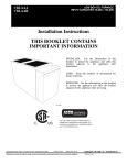
Installation
Instructions
THIS BOOKLET CONTAINS
IMPORTANT INFORMATION
INSTALLER:
Use
booklet
to install
booklet
adjacent
installation.
I
the
information
in
this
the appliance
and affix this
to
the
appliance
after
s
\
USER:
Keep
future reference.
this
booklet
of
information
for
o%
SERVICER:
Use the information
to service
the appliance
adjacent to the appliance
(-\
in this booklet
and affix the
after servicing.
booklet
Al1540
®
Use of the AttRI
C
Copyright
2011 CAC / BDP •
Manufacturer
reserve8
7310 W. Morris St. •
the right to change,
US
Indianapolis,
at any time,
IN 46231
specification8
Printed in U.S.A.
and design8
Certified
manufacturer's
participation
verification
of certification
go to www.ahridirectory.org.
without
notice
Edition
and without
Date:
11/11
obligations.
TM Mark indicates
a
in the program.
For
for individual products,
Catalog
Replaces:
No: IM-CBM-02
IM-CBM-Ol
/ X40190 Rev. B
/ X40190 Rev. A
TABLE OF CONTENTS
1.0
FIGURES
SAFETY REGULATIONS
Figure 1 : Counterflow position, flue pipe )rotection ............ 5
1.1
DANGER, WARNING AND CAUTION
1.2
SAFETY INSTALLATION
2.0
REQUIREMENTS
3
........ 3
INSTALLATION
Figure 2 :Wiring
diagram,BVSO
..........................................
8
Figure 3 : Blocked vent shut-off device wrong, upflow
installation with vertical exhaut .............................
8
Figure 4 : Blocked vent shut-off device wrong, upflow
installation with vertical exhaust ........................... 9
2.1
GENERAL
2.2
SAFE INSTALLATION
2.3
SAFETY RULES
4
2.3.1
Detector
4
2.3.2
Freezing temperatures
2.4
3
REQUIREMENTS ............
4
and your building ...... 4
LOCATION
installation with horizontal exhaust ....................... 9
Figure 6 : Blocked vent shut-off device wiring, horizontal
installation with horizontal exhaust ....................... 9
Figure 7 : Blocked vent shut-off device wiring, downflow
5
installation ............................................................
5
Figure 8 : Blocked vent shut-off device wiring, downflow
6
installation ............................................................
Air for combustion
2.4.2
Duct recommendations.
2.4.3
Venting instructions
2.4.4
Draft Regulator
7
Figure 10 : Model CBM Size 105 ........................................
16
2.4.5
Blocked vent shut-off (B VSO)
7
Figure 11 : Model CBM Size 120 ........................................
17
2.4.6
Oil burner
9
Figure 12 :Wiring
2.4.7
Electrical system ....................................
10
Figure 13 : Wiring diagram CBM, RielIo burner .................. 19
2.4.8
Air filter ................................................
10
Figure 14 : Parts list - CBMAAA036105
.............................
2.4.9
Air Conditioner
10
Figure 15 : Parts list- CBMAAA060120
...............................
10
Figure 16 : Parts List - CBMAAR036105
............................
24
Figure 17 : Parts list- CBMAAR060120
.............................
26
3.0
(chimney installation) ..... 6
(or Heat Pump)
Horizontal or downflow installation
OPERATION
SUPPLY AIR ADJUSTMENTS
11
3.2
OPERATIONAL
11
3.3
PURGING THE OIL LINE.
11
3.4
COMBUSTION
12
3.5
LIMIT CONTROL CHECK
CHECKLIST-
CHECK
Figure 9 : Blower Start/Stop delays Board # 1158 .............. 11
diagram CBM, Beckett burner ............... 18
20
TABLES
Table 1 Minimum dimensions
YEAR ROUND AIR CONDITIONING
12
3.7
HEATING
12
3.8
COOLING
12
3.9
CONSTANT
MAINTENANCE
Filter rack fiance dimensions for return air duct... 10
Table 3
Blower speed adjustments, 4 speed motor,
heating mode ......................................................
12
12
4.1
HEAT EXCHANGER
CLEANING
4.2
BLOWER REMOVAL
4.3
BLOCKED VENT SHUT OFF (BVSO)
CLEANING
FURNACE INFORMATION
13
13
13
14
5
Table 2
Table 4
BLOWER SWITCH
required in ventilation
openings .................................................................
12
3.6
4.0
9
11
3.1
5.0
9
2.4.1
2.4.10
and ventilation
Figure 5 : Blocked vent shut-off device wiring, upflow
11
Blower speed adjustments, 4 speed motor,
cooling mode .......................................................
11
Table 5
Technical Specifications ......................................
14
Table 7
Minimum clearances to combustible
materials .... 16
Table 8
Minimum clearances to combustible
materials .... 17
Table 9
Parts list- CBMAAA036105 .................................
21
Table 10 : Parts list- CBMAAA060120 ...............................
23
Table 11 : Parts list- CBMAAR036105
..............................
25
Table 12 : Parts list- CBMAAR060120
..............................
27
1.0
SAFETY REGULATIONS
IMPORTANT:
All local and national code requirements
governing the installation of oil burning equipment, wiring
and flue connections must be followed. Some of the codes
that may be applicable are:
CSA B139
Installation Code for Oil Burning
Equipment
ANSI/NFPA 31
Installation of Oil Burning Equipment
FOR YOUR SAFETY
DO NOT STORE
OR USE GASOLINE
OR OTHER
FLAMMABLE VAPOURS AND LIQUIDS IN THE VICINITY
OF THIS OR ANY OTHER APPLIANCE.
DO NOT ATTEMPT TO START THE BURNER WHEN
EXCESS
OIL
HAS
ACCUMULATED.
WHEN
THE
FURNACE
IS FULL OF VAPOUR
OR WHEN
THE
COMBUSTION CHAMBER IS VERY HOT.
ANSI/NFPA 90B Warm Air Heating and Air Conditioning
Systems
ANSI/NFPA 211 Chimneys, Fireplaces, Vents and Solid
Fuel Burning Appliances
ANSI/NFPA 70
National Electrical Code
1.1
CSA C22.2 No.3 Canadian Electrical Code
DANGER, WARNING AND CAUTION
The words DANGER, WARNING and CAUTION are used to
identify the levels of seriousness of certain hazards. It is
important that you understand their meaning. You will notice
these words in the manual as follows:
_1_
DANGER
Only the latest issues of the above codes should be used,
and are available from either:
The National Fire Protection Agency
1 Batterymarch Park
Quincy, MA 02269
or
The Canadian Standards Association
178 Rexdale Blvd.
Rexdale, Ontario M9W 1R3
ENVIRONMENTAL
Hazards or unsafe practices which CAN result in death
or serious bodily and/or material damage.
Failure
to
follow
this
environmental pollution.
SAFETY INSTALLATION
caution
may
result
in
Remove and recycle all components or materials (i.e.
oil, electrical and electronic components,
insulation,
etc.) before unit final disposal.
Hazards or unsafe practices which CAN result in minor
bodily and/or material damage.
1.2
HAZARD
REQUIREMENTS
For use with grade 2 fuel oil maximum. Do NOT use
gasoline, crankcase oil or any oil containing gasoline.
2.0
INSTALLATION
2.1
GENERAL
This central heating unit is a true multi-position unit, in that it
can operate in four different configurations,
i.e., upflow,
counter flow (downftow), and horizontal (both left-to-right
and right-to-left airflow).
Very few modifications are required during installation, to
change the furnace from one configuration to another. The
furnace is shipped in the upflow configuration; however,
instructions on how to change to the other configurations are
included in this manual.
Never burn garbage or paper in the heating system and
never leave rags or paper around the unit.
These instructions
are intended for the sole use of
qualified personnel trained in installing this type of
furnace. Installation of this furnace by an unqualified
person can lead to hazardous conditions, resulting in
I
l
I
I
I
The furnace is shipped complete with burner and controls. It
requires a 115VAC line voltage connection to the control
panel, thermostat hook-up as shown on the wiring diagram,
one or more oil line connections,
suitable ductwork and
connection to a properly sized vent.
bodily harm and/or equipment
I
The air handling capacity of this furnace is designed for
cooling as well. Please refer to Table 6 for the expected
airflow at various external static pressures.
damage.
=
2.2
SAFE INSTALLATION
REQUIREMENTS
2.3
Your unit is built to provide many years of safe
dependable service, provided it is properly installed
maintained.
However, abuse and/or improper use
shorten the life of the unit and create hazards for you,
owner.
Installation or repairs performed by unqualified persons
can result in hazards to them and others. Installation
MUST conform to local codes or, in the absence of
same, to codes of the country having jurisdiction.
2.3.1
The information contained in this manual is intended for
use by a qualified service technician familiar with safety
procedures and quipped with the proper tools and test
instruments.
a.
Failure to carefully read and follow all instructions in
this manual can result in death, furnace malfunction
and/or property damage.
I FIRE HAZARD
I
The furnace must be installed in a level position, never I
where it will slope toward the front. If the furnace is not I
installed level, oil will drain into the furnace vestibule I
and create a fire hazard.
b.
I
NOTE: It is the personal responsibility and obligation of the I
customer to contact a qualified installer to ensure that the I
installation conforms to governing local and/or national I
codes and ordinances
I
I
a.
b.
This furnace is NOT approved for installation in mobile
homes, trailers or recreational vehicles;
Do NOT use this furnace as a construction heater or to
heat a building under construction;
c.
There must be a sufficient supply of fresh air for
combustion as well as ventilation in the area where the
furnace is located;
d.
Use only the type of fuel oil approved for this furnace
(see section 1.2 of this manual). Overfiring will result in
heat exchanger failure and cause dangerous operating
conditions;
e.
Visually check all oil line joints for signs of leakage;
f.
Connect furnace to the chimney;
g.
The points in Part 3 "Operation" are vital to the proper
and safe operation of the heating system. Take the time
to ensure that aII steps were followed;
h.
Follow the regulations of the NFPA No.31 (in the USA)
and CSA B-139 (in Canada) or local codes for placing
and installing the oil storage tank;
i.
Follow a regular service and maintenance
efficient and safe operation;
j.
Before servicing, allow furnace to cool down. Always
shut off electricity and fuel to furnace when servicing.
This will prevent electrical shock or burns;
SAFETY RULES
and
and
can
the
Detector
The U.S. Consumer
Product
Safety Commission
recommends that users of oil-burning appliances install
carbon monoxide detectors. There can be various
sources of carbon monoxide in a building or dwelling.
The sources could be gas-fired clothes dryers, gas
cooking stoves, water heaters, furnaces,
gas-fired
fireplaces, wood fireplaces, and several other items.
Carbon monoxide can cause serious bodily injury
and/or death.
Therefore,
to help alert people to
potentially dangerous
carbon monoxide levels, you
should have carbon monoxide detectors listed by a
nationally
recognised
agency
(ex.
Underwriters
Laboratories
or International
Approval
Services)
installed and maintained in the building or dwelling (see
Note below).
There can be numerous sources of fire or smoke in a
building or dwelling. Fire or smoke can cause serious
bodily injury, death, and/or property damage. Therefore,
in order to alert people to potentially dangerous fire or
smoke, you should have fire and smoke detectors listed
by Underwriters Laboratories installed and maintained
in the building or dwelling (see Note below).
NOTE: The manufacturer of your furnace does not test any I
I
detectors and makes no representations
regarding any I
brand or type of detector.
I
Ensure that the area around the combustion
free of snow, ice and debris.
2.3.2
Freezing temperatures
FREEZING TEMPERATURE
air intake is
and your building
WARNING
Seal supply and return air ducts;
I.
The vent system MUST be checked to determine that it
is the correct type and size;
m.
Install correct filter type and size;
n.
Unit MUST be installed so that electrical components
are protected from direct contact with water.
I
Turn off water supply.
I
If your heater remains shut off during cold weather, the I
water pipes could freeze and burst, resulting in serious I
water damage.
schedule for
k.
I
I
If the structure is unattended during cold weather you should
take the following precautions:
a.
Turn off main water supply into the structure and drain
the water lines if possible. Open faucets in appropriate
areas;
b.
Have someone check the structure frequently during
cold weather to make sure it is warm enough to prevent
pipes from freezing. Contact a qualified service agency,
if required.
I
2.4
LOCATION
This furnace is not watertight
and is not designed for
outdoor installation. This furnace shall be installed in
such a manner as to protect the electrical components
from water. Outdoor installation will lead to hazardous
I
I
I
I
I
electrical conditions and to premature furnace
I
failure.
I
If this furnace is installed in an attic, it is important to I
keep insulation at least 0.3 m (12") away from any I
furnace openings. Some types of insulating material l
may be combustible.
I
The unit must be installed in a location where the ambient
and return air temperature is over 15°C (601=).
This furnace
is approved
for reduced clearances
to
combustible construction. Therefore, it may be installed in a
closet or similar enclosure. As this unit may be installed as
an upftow, counter flow, or horizontal furnace, it may be
located in a basement, on the same level as the area to be
heated, suspended, or in a crawlspace. In any case, the unit
should always be installed level.
In a basement, or when installed on the floor (as in a
crawlspace), it is recommended that the unit be installed on
a concrete pad that is 2.5 cm to 5.0 cm (1" to 2") thick.
When installed in the counter flow position, this furnace
must not be installed on combustible flooring, unless the
approved sub-base is used (Model # KLASB0601DET).
Since the flue pipe is in counter flow position, be sure that
the clearances
from
the flue pipe to combustible
construction are maintained. Also, it is recommended to use
the
flue
pipe
protection
kit
KLADC0101 DET
or
KLADC0201DET.
Please refer to the Figure 1 and the
installation instructions included with the kit.
Figure 1 : Counterflow
When installed in an horizontal position, the furnace may be
suspended by using an angle iron frame, as long as the total
weight of both the furnace and the frame are included in the
calculations. Other methods of suspension are acceptable.
When installed in the horizontal position, this furnace must
not be installed on combustible
flooring,
unless the
approved sub-base is used (Model KLASB0701DET).
The required minimum clearances for this furnace
positions are specified in Tables 7 and 8.
in all
The furnace should be located as closely as possible to the
chimney or vent in order to keep vent connections short and
direct. The furnace should also be located near the centre of
the air distribution system.
2.4.1
Air for combustion
and ventilation
This furnace should be installed in a location in which the
facilities for ventilation permit satisfactory combustion of oil,
proper
venting
and
the
maintenance
of
ambient
temperatures at safe limits under normal conditions of use.
The location should not interfere with the proper circulation
of air within the confined space.
Refer to the CAN/CSA-B139 installation code for complete
regulations, and for guidance on retrofit applications.
When this furnace is installed in a closet or similar
enclosure,
2 ventilation
openings
are
required
for
combustion air. The openings should be located about 15.2
cm (6") from the top and the bottom of the enclosure at the
front of the furnace.
Table 1 indicates the minimum
dimensions
required for each of these two ventilation
openings.
Table 1 : Minimum dimensions required in ventilation
openings
Input
(BTU/h)
75,000 - 105,000
120,000 - 155,000
Width
Height
45.72 cm (18")
50.80 cm (20")
20.32 cm (8")
25.40 cm (10")
position, flue pipe protection
furnace.
Any
blockage
will
result
in improper
combustion
and
may
result
in
a
fire
hazard
and/or in
cause
I Do not block the combustion
air openings
the
bodily harm.
KLADC0101DET/
KLADC0201 DET
The barometric draft regulator included with the furnace,
shall be installed in the same room or enclosure as the
furnace, in such a manner as to prevent any difference in
pressure between the regulator and the combustion air
supply.
Air requirements for the operation of exhaust fans, kitchen
ventilation systems, clothes dryers, and fireplaces shall be
considered in determining the adequacy of the space to
provide combustion air requirements.
DNS-0278
Rev. A
In unconfined spaces, in buildings of conventional frame,
brick or stone construction, infiltration may be adequate to
provide air for combustion, ventilation and dilution of flue
gases. This determination must be made on an individual
installation
basis and must take into consideration
the
overall volume of the unconfined space, the number of
windows
andventilation
openings,
thenumberof doorsto
the outside,internaldoorswhichcan closeoff the
unconfined
spaceand the overallair tightnessof the
building
construction.
Manynewbuildings
andhomes(andolderonesthathave
beenweatherized
mustbe considered
as beingtight
construction
and,therefore,
infiltration
willnotbesufficient
to
supply
thenecessary
airforcombustion
andventilation.
Abuilding
canbeconsidered
asbeingoftightconstruction
when:
a. Wallsandceilingsexposedto the outsidehavea
continuous
watervapourretarder
witha ratingof one
permor less,openings
havegasketsor aresealed
and/or;
b. Weather-stripping
has been added on operable
windows
anddoors,and/or;
c. Caulking
or sealant
hasbeenappliedtoareassuchas
jointsaroundwindowanddoorframes,
between
sole
platesandfloors,between
wail-ceiling
joints,between
wallpanels,atpenetrations
forplumbing,
electrical
and
fuellinesandatotheropenings.
2.4.2
Duct recommendations
When ducting supplies air to a space other than where
the furnace is located, the return air must be sealed and
also be directed to the space other than where the
furnace is located. Incorrect ductwork termination and
sealing will create a hazardous condition that can lead
to bodily harm.
Also, there is provision on this furnace for a bottom return air
duct. Knockouts are provided in the floor of the furnace to
facilitate the cut-out requirement for the air filter rack and
return ductwork. (We recommend the use of this opening for
horizontal and counterflow installations).
The following recommendations
installing ductwork:
a.
should
be followed
Install locking type dampers in all branches of the
individual ducts to facilitate balancing the system.
Dampers should be adjusted such a way as to ensure
the proper static pressure at the outlet of the furnace;
A flexible duct connector of non-combustible
material
should be installed at the unit on both the supply and
return air side. In applications where an extremely quiet
operation is necessary, the first 3 m (10') of supply and
return ducts should be internally lined with acoustical
material (if possible);
b.
c.
In cases where the return air grille is located close to
the fan inlet, there should be at least one 90 ° turn
between fan inlet and grille. Further reduction in sound
level can be accomplished
by installing acoustical
turning vanes or lining the duct as described in item b.
above;
d.
When a single air grille is used, the duct between grille
and furnace must be the same size as the return air
opening in the furnace.
When installing the furnace with cooling equipment for year
round operation, the following recommendations
must be
followed for tandem or parallel air flow:
POISONOUS
CARBON MONOXIDE GAS HAZARD
Install the evaporator coil on the supply
furnace ducting ONLY.
Return air grilles and warm air registers
obstructed.
must not be
IMPORTANT: The dampers should be adequate to prevent
cooled air from entering the furnace, and if manually
operated, must be equipped with the means to prevent
operation of either the cooling unit or the furnace, unless the
damper is in the full cool or heat position.
NOTE:
The back
ducting.
should
not be cut out for return
air
The proper sizing of warm air ducts is necessary to ensure
satisfactory
furnace operation.
Ductwork should be in
accordance
with
the
latest
editions
of
NFPA-90A
(Installation of Air Conditioning and Ventilating Systems)
and NFPA-90B (Warm Air Heating and Air Conditioning
Systems) or Canadian equivalent.
The supply ductwork should be attached to the flanged
opening provided at the discharge end of the furnace. See
Figures 10 and 11, for the dimensions of this opening.
Knockouts are provided on both sides of the furnace to cut
the required size of opening for the installation of the return
air ductwork. This can be done on either the right or the left
side of the furnace.
See Table 2 for location
and
dimensions.
when
side of the
An evaporator coil installed on the return air side of the
ducting can cause condensation to form inside the heat
exchanger, resulting in heat exchanger failure. This in
turn can result in death, bodily injury.
a.
On tandem airflow applications, the coil is mounted
after the furnace in an enclosure in the supply air
stream. The furnace blower is used for both heating and
cooling airflow;
b.
On parallel airflow installation,
dampers must be
provided to direct air over the furnace heat exchanger
when heat is desired and over the cooling coil when
cooling is desired.
2.4.3
Venting instructions
(chimney installation)
The furnace must be vented to the outside, in accordance
with local codes and other authorities having jurisdiction.
Oil fired appliances must be connected to flues having
sufficient draft at all times to ensure safe and proper
combustion.
For
additional
venting
information
please
refer
to
ANSI/NFPA 211 Chimneys, Fireplaces, Vents and Solid
Fuel Burning Appliances and/or the CSA B139 Installation
Code.
Thisfurnaceis certifiedfor use witha Type"L" vent
(maximum
fluegastemperature
30213(5751=)).
Thef Iue
pipeclearance
knockout
inthefronttoporsidepanelshould
beremoved.
Install
theflueelbowsothatitexitsthefurnace
cabinet
through
thatopening.
Factory Built Chimneys
Approved factory built chimneys may be used. Refer to
chimney manufacturer's instructions for proper installation.
2.4.4
Pre-installation
Draft Regulator
vent system inspection
Before this furnace is installed, it is strongly recommended
that any existing vent system be completely inspected.
On any chimney or vent, this should include the following:
a.
Inspection for any deterioration
If deterioration is discovered,
repaired or the vent replaced;
in the chimney or vent.
the chimney must be
b.
Inspection to ascertain that the vent system is clear and
free of obstructions. Any blockages must be removed
before installing this furnace;
c.
Cleaning the chimney or vent if previously used for
venting a solid fuel burning appliance or fireplace;
d.
Confirming that all unused chimney or vent connections
are properly sealed;
e.
Verification that the chimney is properly lined and sized
per the applicable codes. (Please refer to list of codes
in Part 1.2)
The draft regulator supplied with the furnace must be used
for proper functioning. Installation instructions are included
with the control.
2.4.5
Blocked vent shut-off (BVSO)
For chimney venting
All oil furnaces
vent shut-off.
installed
It is imperative
qualified agency.
that
in Canada
this
device
must have a blocked
be
installed
by a
This device is designed to detect the insufficient evacuation
of combustion gases in the event of a vent blockage. In such
a case the thermal switch will shut down the oil burner. The
device will then need to be re-armed MANUALLY.
Masonry Chimneys
This furnace may be vented into an existing masonry
chimney. However, it must not be vented into a chimney
servicing a solid fuel-burning appliance. Before venting this
furnace into a chimney, the chimney must be checked for
deterioration and repaired if necessary. The chimney must
be properly lined and sized per local and/or national codes.
The chimney must be of sufficient area to accommodate the
total flue products of all appliances vented into the chimney.
The following requirements
system:
For more details, refer to the instructions supplied with the
device itself, as well as section 3 of this manual.
are provided for a safe venting
a.
Ensure
debris;
b.
Ensure that the chimney
fireplace;
c.
Never reduce the pipe size below the outlet size of the
furnace;
d.
All pipes should be supported, using the proper clamps
and/or straps. These supports should be installed at
least every 4 feet;
e.
All horizontal runs of pipe should have at least 20 mm
of upward slope per 1 m (1/4" per 1');
f.
All runs of pipe should be as short as possible with as
few turns as possible;
g.
Seams should be tightly joined and checked for leaks;
h.
The flue pipe must not extend into the chimney but be
flush with the inside wail;
i.
The chimney must extend 0.9 m (3') above the highest
point where it passes through a roof of a building and at
least 0.6 m (2') higher than any portion of a building
within a horizontal distance of 3 m (10'). It shall also be
extended
at least 1.5 m (5') above the highest
connected equipment flue collar;
j.
Please refer to Figures 2 to 8, the wiring diagrams, Figures
12 and 13, and the detailed instructions supplied with the
BVSO for the installation and wiring procedures. The length
of wires supplied with the unit is such that the safety device
must be installed between the flue outlet of the appliance
and the draft regulator, as indicated in the instructions.
that the chimney
flue
is clear of any dirt or
is not servicing
Check local codes for any variances.
an open
FIRE, CARBON MONOXIDE POISONINC
HAZARD
Failure to follow this warning could result in personal
injury, death, and/or property damage.
DO NOT reset the device or restart the furnace
unless
the cause of the interruption has been identified and
corrected by a qualified agency. Ensure that the blocked
vent shut-off has been cleaned by a qualified agency
before placing into service. Annual inspection and
cleaning of the blocked vent shut-off by a qualified
agency is required.
FIRE, CARBON MONOXIDE POISONINC
HAZARD
Failure to follow this warning could result in personal
injury, death, and/or property damage.
The blocked vent shut-off MUST be inspected
maintained annually by a qualified agency.
and
It is also essential that the BVSO be maintained annually.
For more details please refer to the instructions supplied
with the device itself, as well as Section 4 of this Manual.
ELECTRICAL
SHOCK
HAZARD
Failuretofollowthiswarningcouldresultinpersonal
injuryordeath.
Disconnectelectricalpower supply to the furnace
beforewiringtheblockedventshut-off.
CUTHAZARD
Failureto follow
this caution
may result
in personal
injury.
Sheet metal parts may have sharp edges or burrs. Use
care and wear appropriate protective clothing, safety
glasses, and gloves when handling parts and servicing
furnaces.
Figure 2 : Wiring diagram,BVSO
120vAC FROM APPLIAbCE
Lli, IT CIRCLIT OR AGEASTAT
N
T
k
(NEUTkAL}
GROUND
EOUIS'ElvlET
,SROL
ND±
RED
y,
(F%b
[:) i
ol
LIMIT
PTYO
120 vA¢ _, L1 (HOT)
FROM
! L2 (NE TRAL)
APr£1ANCE
f
P,
S
BLACK
_
0 *
L/
O_ BELECTE@I!ODELS
WHITE
vIOLET
Sa
V SAFETY LIMIT SWITCH
oi
TO RE/IOTE LOW ,iOL%GE
x,C ,&LARk ,31DSUIT(IF t SED'
LI,IT CIRCUIT)
BLUE
:}_/_N'SE
L2
,_L',,,'EPRIMARY
CONTROL
IGNITION
MOTOR
TC_
YELLOW
>
YELLO'hi
CAD CELL
'3_0 ,SELL
TO
24 ,,/AC
THERbOSTAT
8VSO
DNS-01340
Beckett Burner
Figure 3 : Blocked vent shut-off
The position of the hole
in the vent is subject to
the length of the
electrical kit.
Rev A
BURNER CONTROL BOX
FsCTORY %RED
Riello Burner
device wiring, upflow installation with vertical exhaut
Blocked Vent Shut-Off
device BVSO.
Electrical kit supplied.
Use the three wire
/I
Connect the green
ground wire to a
cabinet screw.
___s
eeft]
.he
and
I
DNS-1043
Rev. A
Figure 4 : Blocked vent shut-off device wiring, upflow
installation with vertical exhaust
Figure 7: Blocked vent shut-off device wiring, horizontal
installation with vertical exhaust
DNS-1043
Rev A
Rev A
Figure 5 : Blocked vent shut-off device wiring, upflow
installation with horizontal exhaust
Figure 8: Blocked vent shut-off device wiring, downflow
installation
/
/
_
L
Connection to
high limit contacts
(See Fioure 2/
/
/
/
_
',
/
/
/
i.
DNS-1043
Rev,
'0 0
Figure 6: Blocked vent shut-off device wiring, horizontal
installation with horizontal exhaust
Connection
gh limit
contacts (See Figure 2)
DNS-1043
2.4.6
Connection
Rev A
Oil burner
This furnace is supplied with a high pressure atomizing
retention head type burner for use with not heavier than
grade 2 Fuel Oil. If the burner model is a Beckett AFG, the
mounting flange is fixed to the burner air tube and no
adjustment is required for length. If a RielIo burner is used,
refer to the Technical Specifications,
Table 5 for the
insertion length.
to
high timit contacts
(See Fiaure 2/
o
o
NEVER use the "interrupted
ignition"
function
Beckett AFG burner is installed on the furnace.
if
a
Oil Connections
Complete instructions for installation of the fuel oil piping will
be found in the oil burner installation instructions included
with the furnace.
Oillineentryholesarelocated
inthesidepanels.
Twoholes
areprovided
oneachside,sothatatwo-pipe
system
canbe
usedifdesired.
Table 2 : Filter rack flange dimensions
Model
CBM SIZE 105
A 10-micron
(orfiner)oilfiltershouldbeusedwithall oil
burners,
installed
asclosely
aspossible
totheburner.
2.4.7
Air Filter Size
16" x 24"
Flange Opening
15" x 23"
40.64 x 60.96 cm
38.10 X 58.42 cm
20" x 30"
17" x 29"
45.72 X 76.20 cm
43.18 X 73.66 cm
CBM SIZE 120
Electrical system
2.4.9
for return air duct
Air Conditioner
(or Heat Pump)
I
unbroken electrical ground to minimize personal injury
if an electrical
fault should
ground screw
IThe
unit cabinet
must occur.
have A
angreen
uninterrupted
or
is provided in the control box for this connection.
An air conditioning
side ONLY.
I
II
coil may be installed on the supply air
I
The appliance must be installed in accordance with the
current ANSI/NFPA 70 National Electrical Code, CSA C22.1
Canadian Electrical Code Part 1 and/or local codes.
POISONOUS
The control system depends on the correct polarity of the
power supply. Connect "HOT" wire (H) and "NEUTRAL" wire
(N) as shown in Figures 12 and 13.
An evaporator coil installed on the return air side of the
ducting can cause condensation to form inside the heat
exchanger, resulting in heat exchanger failure. This in
turn can result in death, bodily injury.
Install the evaporator coil on the supply
furnace ducting ONLY.
A separate line voltage supply should be used with fused
disconnect switch or circuit breaker between the main power
panel and the unit.
Metallic conduit (where required/used) may terminate at the
side panel of the unit. It is not necessary to extend the
conduit inside the unit from the side panel to the control box.
When replacing any original furnace wiring, use only 105°C,
16 AWG copper wire.
of the
If a coil blower compartment
is used, install air tight,
motorized and automatic air dampers. Cold air coming from
the coil and passing across the furnace can cause
condensation and shorten the life of the heat exchanger.
Instructions for wiring the thermostat are provided with the
thermostat (field supplied). Wire the connections to the 24volt terminal board on the primary relay as shown in Figures
12 and 13.
2.4.10
When installing optional accessories
to this appliance,
follow the manufacturer's
installation instructions included
with the accessory. Other than wiring for the thermostat,
wire with a minimum of type "T" insulation (17°C rise (63°F))
must be used for accessories.
An external filter rack is provided as standard equipment
with this furnace. The filter rack can be installed on the right
or left side panel, or on the bottom of the furnace to
accommodate the return air ductwork. A sufficient clearance
should be provided for air filter access. Please refer to Table
2 for filter rack flange dimensions for return air duct.
Horizontal or downflow
installation
1.
On horizontal installations, determine which "side" will
become the "top", when the unit is laid down. Remove
the flue pipe clearance knockout from the top front of
that side panel. Install the flue elbow so that it exits the
cabinet of the furnace through that opening;
2.
On counterflow Installations, the flue pipe must exit the
cabinet through one of the side panel openings (as
above), then extended up the side of the furnace.
Ensure that adequate clearances to combustibles are
observed. It may be necessary to install a sheet-metal
shield on an adjacent wall to prevent any possibility of a
fire hazard;
3.
Remove the burner.
If it's a Beckett burner models,
loose the mounting nuts and turn the oil burner slightly
counter clockwise to unlock the burner flange. For the
RieIIo burner models, unscrew the mounting nuts.
Avoid putting undue strain on burner wiring. It may be
necessary to disconnect the burner wiring in some
cases;
To reinstall the Beckett burner, insert the burner in the
burner flange bolts and turn the burner clockwise to lock
it; then tighten the nuts.
Air filter
_1_
side
No minimum clearance is required between the bottom of
the coil drain pan and the top of the heat exchanger. If a
heat pump is installed, a "dual-energy" thermostat, or other
control is required, in order to prevent the simultaneous
operation of the furnace and the heat pump. It also prevents
a direct transition from heating by way of the heat pump to
heating with oil. Refer to the thermostat instructions or those
of another control used for the proper wiring.
Use only copper wire for 115V supply service to the unit.
2.4.8
CARBON MONOXIDE GAS HAZARD
DANGER
4.
I IMPORTANT:
must control
alwaysonbe
upright position The
with burner
the ignition
top.installed
10
I
in the I
3.0
OPERATION
3,2
3.1
SUPPLY AIR ADJUSTMENTS
Before starting up the unit, be sure
following items are in compliance:
This unit is equipped with 4-speed blower motors. The
supply air must be adjusted
based
on heating/air
conditioning output and the static pressure of the duct
system. For the desired air flow please refer to Table 3 and
4 as well as the air flow Table 6 based on static pressure in
the Technical Specifications, Table 5, of this manual.
Table 3 : Blower speed adjustments,
heating mode
FURNACE
MODEL
HEATING
INPUT
0.50 USGPH
0.65 USGPH
0.75 USGPH
0.85 USGPH
1.00 USGPH
1.10 USGPH
CBM SIZE 105
CBM SIZE 120
4 speed motor,
RECOMMENDED
BLOWER SPEED
MED-LOW
MED-HIGH
HIGH
MED-LOW
MED-HIGH
HIGH
To effect the adjustment, the RED and BLUE wires can be
changed on the motor. Also, please refer to the position of
the wires on the electronic board of the unit and consult the
wiring diagrams. If the heating and the air conditioning
speeds are the same, the RED wire must be moved to
"UNUSED LEADS" on the electronic board and the jumper
provided with the BLUE wire must be used between the
"HEAT" and "COOL" terminals.
Table
4 : Blower speed adjustments,
cooling mode
FURNACE
MODEL
COOLING
CAPACITY
2.0 TONS
2.5 TONS
3.0 TONS
3.5 TONS
4.0 TONS
5.0 TONS
CBM SIZE 105
CBM SIZE 120
oi
4 speed motor,
2i
i20 Sec
DELAY ON
0
N
;
2J.34
l 3E
t
2 v it'
DELAY OFF
The Blocked Vent Shut-Off
(BVSO)
is
according to instructions (for chimney venting);
4.
5.
The oil supply valve is open;
The flame observation door and the two clean-out
access doors (located at the front of the unit) or well
closed;
6.
The burner "Reset"
armed;
7.
The preliminary air adjustments on the burner comply
with the technical specifications in this manual;
8.
The blower speed adjustments for heating and air
conditioning
are appropriate
and according
to the
specifications in this manual;
9.
The blower start/stop delays are satisfactory;
button
is well pushed
installed
in or re-
i
_
I v ir
i {},ELAY OFF
11
Call
a
PURGING THE OIL LINE
A 10-micron (or less) oil filter should be installed as
closely to the burner as possible with all oil burners, but
it is essential for burners with a low firing rate. We
recommend the use of a low pressure drop oil filter with
a capacity greater than that of the fuel pump;
On a new installation, the air trapped in the oil line
leading from the tank to the nozzle must be thoroughly
purged in order to prevent excessive after drip. The oil
pump is equipped with a special fitting that facilitates
the purging of any air between it and the tank. The
proper procedure for performing this operation is as
follows:
a.
Place a piece of 1/4" diameter clear plastic tubing
over the purge fitting on the oil pump;
b.
Start the oil burner, then open the purge fitting and
allow the burner to run until the purge tube is
completely free of air bubbles;
c.
At this point tighten the purge fitting, which will
allow the oil to run to the nozzle and fire the burner.
If the purging takes longer than 15 seconds and no
flame has been established the burner will stop.
Push the reset button on top of the Primary Control
to restart the burner.
_
,t ,',tl=Et
ON
3.
,J
s, 12:_4
........
DEL_,Y
The blower access door is in place and the blower rail
locking screws are well tightened;
2.
9,{ Sec
J
4 I',,'lin
DELAY ON Ii C'EL£Y 'OFF
i
60 Sec
{DELAY ON
2.
1.
i
6 'vin
DELAY OFF
The electrical installation, the oil supply system, the
venting system, combustion air supply and ventilation;
3.3
iqF=Pq
i
that the
1.
Do not tamper with the unit or its controls.
qualified service technician.
RECOMMENDED
BLOWER SPEED
MED-LOW
MED-HIGH
HIGH
MED-LOW
MED-HIGH
HIGH
,Jl
to check
To start the unit, turn the main electrical switch on.
delays Board # 1158
2i;4
CHECKLIST
10. The thermostat of the room is in the heating mode and
is set higher than the ambient temperature.
The blower start/stop delays can be adjusted by positioning
the DIP switches on the electronic board as shown on the
Figure 9.
Fi.qure 9 : Blower Start/Stop
OPERATIONAL
For detailed information on the operation of the Primary
Control please refer to the instructions included with the
furnace or the burner.
3.4
COMBUSTION
CHECK
values. A high pressure condition may be caused by
excessive combustion air due to the air band being too
wide open or a lack of flue draft (chimney effect) or
some other blockage, such as soot in the secondary
section of the heat exchanger or the use of an oversize
nozzle input or high pressure pump;
IMPORTANT:
The heat exchanger metal surfaces may
have oil and the baffle insulation also contains binders.
These products will burn or evaporate when the unit
operates for the first time. Because of this, the smoke
reading may be inexact during the first minutes of operation.
Therefore, the unit must operate during at least 60 minutes
before taking any readings to adjust the combustion quality.
Let the unit cool down before making any adjustments.
IMPORTANT:
The combustion check verification MUST be
performed after the nozzle replacement or the burner
cleaning.
After
these
manipulations,
the combustion
parameters are necessarily modified. Refer also to the
burner instruction manual.
6.
I
I
I
I
I
3.5
2.
3.
5.
3.6
to do the combustion
YEAR ROUND AIR CONDITIONING
The furnace is designed for use in conjunction with cooling
equipment, to provide year round air conditioning.
The
blower has been sized for both heating and cooling;
however, the fan motor speed may need to be changed to
obtain the necessary cooling airflow.
The proper smoke number, as established by way of
engineering tests, is between 0 and 1. This degree of
smoke emission is commonly referred to as a "trace". It
is recommended that a Bacharach True Spot Smoke
Test kit or equivalent be used;
a.
4.
Remove the restriction and the burner should come back on
in a few minutes.
A test kit to measure the smoke, flue draft and over-fire
pressure should be used in order to obtain the proper
air
band
setting.
Although
all of
the above
measurements
are required for optimum set up and
efficiency, the most important reading that must be
taken is the smoke number in the flue pipe, downstream
from the regulator;
Follow the next steps
verification:
LIMIT CONTROL CHECK
After the furnace has been in operation for at least 15
minutes, restrict the return air supply by blocking the filters
or closing the return registers and allow the furnace to shut
down on High Limit. The burner will shut OFF but the main
blower should continue to run.
In order to obtain optimum performance from the oil burner,
the following set-up procedures must be followed
by
referring to the Technical Specifications,
Table 5 in this
manual:
1.
After all the set up procedures mentioned above have
been completed, the burner should be fired and an
inspection mirror should be used to observe the flame
pattern at the tip of the nozzle. Any irregularities such
as burning to one side or pulsating flame patterns
should be corrected by changing the nozzle.
3.7
check
HEATING
The blower speed is factory set to deliver
airflow at normal duct static pressure.
Drill a minimum proper diameter (about 9/32") test
hole in the flue pipe, approximately 18 inches from
the furnace breech;
3.8
the required
COOLING
b.
From a cold start, let the unit operate for about 5
minutes;
c.
Set the burner air setting until you have between 0
and 1 on the Bacharach Scale (or a "trace");
d.
Take a CO2 sample at the same test location where
the smoke reading was taken and make note of it;
3.9
e.
Adjust the burner air setting to obtain a CO2 reading
1.5% lower (or a 02 reading 2.0% higher) than the
reading associated with the "trace" of smoke;
f.
This method of adjusting the burner will result in
clean
combustion
(Bacharach
smoke
scale
between 0 and a trace) and ensure the proper
functioning of the system.
This furnace is equipped with a constant low speed blower
option. Whenever the room thermostat is not calling for
heating or cooling, the blower will run on low speed in order
to provide air circulation. If this constant blower option is not
desired, the rocker switch on the side of the control box can
be used to turn it off.
The blower speed may be adjusted in the field to deliver the
required airflow for cooling applications,
as outlined in
Table 4.
A barometric draft regulator, supplied with the furnace,
must be installed, in order to ensure proper draft
through the furnace. The barometric damper must be
mounted with the hinge pins in a horizontal position and
the face of the damper vertical for proper functioning,
(see instructions
included with damper). After the
furnace has been firing for at least five minutes, the
draft regulator should be set to between -0.025" W.C.
and -0.035" W.C.;
4.0
CONSTANT
BLOWER SWITCH
MAINTENANCE
I
Before performing any service functions, make sure that I
all utilities are turned "OFF"
upstream from
the I
appliance, unless operations specifically require the I
power to be on. Failure to comply with this warning will I
cause a fire hazard and/or bodily harm.
The over fire pressure that is taken through the
observation door located in the centre of the front panel
above the burner is a measurement that is necessary to
determine if there is a blockage in the heat exchanger
or the flue pipe. Please refer to the Technical
Specifications
in this manual for over fire pressure
I
12
This furnace should never be operated without an air filter.
Disposable filters should be replaced at least once a year. If
equipped to provide cooling, filters should be replaced at a
minimum of twice a year.
To avoid personal
before servicing.
injury, make sure the power
is "OFF"
ALWAYS
KEEP THE OIL VALVE
CLOSED
BURNER IS SHUT DOWN FOR AN EXTENDED
OF TIME.
IF THE
PERIOD
4.
After replacing the nozzle, the burner should be adjusted in
accordance with the "COMBUSTION CHECK" section of this
manual.
2.
Disconnect the flue pipe (only with chimney venting and
rigid flue pipe);
3.
Remove the breech plate;
4.
5.
Remove the radiator baffle;
Disconnect the oil line and remove the oil burner from
the furnace;
6.
Open the two cIeanout doors located in the upper part
of the front panel of the furnace;
7.
Clean the secondary tubes and the primary
with a stiff brush and a vacuum cleaner;
8.
Before reassembty, the heat exchanger and combustion
chamber
should
be inspected
to determine
if
replacement is required;
9.
After cleaning, replace the radiator baffle, flue collar
plate, oil burner and close the two clean out access
doors. Reconnect the flue pipe and oil line;
the
Slide the blower on the rails toward the front of the unit;
6.
Reverse the above steps to reinstall the blower. Please
refer to the wiring diagrams, Figures 12 and 13 in this
manual, or the diagram located on the inside of the
blower door to properly rewire the unit.
BLOCKED VENT SHUT OFF (BVSO) CLEANING
ELECTRICAL
Failure
injury
If cleaning is necessary, the following steps should be taken:
upstream
disconnect
For continued safe operation, the Blocked Vent Shut-Off
System (BVSO) needs to be inspected and maintained
annually by a qualified service technician.
Normally, it is not necessary to clean the heat exchanger or
flue pipe every year, but it is advisable to have a qualified
service technician check the unit before each heating
season to determine whether cleaning or replacement of
parts is required.
Turn "OFF" all utilities
and
5.
4.3
CLEANING
1.
box cover
sliding it off the mounting rails, especially
in the
horizontal or counter flow positions, in order to prevent
it and
injuringis adequately
yourself orsupported
damaging when
the
I dropping
Be sure that
the blower
blower.
The procedure for the installation and/or replacement of a
nozzle is outlined in the oil burner instruction manual which
is supplied with the furnace.
HEAT EXCHANGER
the control
thermostat and power wires from the board;
For optimum performance, the oil burner nozzle should be
replaced at least once a year.
4.1
Remove
to follow
before
cylinder
this
HAZARD
warning
could
result
in
personal
the
furnace
or death.
Disconnect
from the furnace;
SHOCK
electrical
servicing
power
the blocked
screws
supply
vent
to
shut-off.
1.
Remove the two
assembly cover;
holding
down
the
BVSO
2.
Remove the cover;
3.
Remove the two screws holding the control box to the
heat transfer tube assembly. Sliding the control box in the
appropriate direction will unlock it form the heat transfer
tube assembly;
4.
Carefully remove any build-up from the thermal
surface;
switch
Do not dent or scratch the surface of the thermal
switch. If the thermal switch is damaged, it must be
replaced.
10. Readjust burner for proper operation.
4.2
5.
Clear and remove any build-up or obstruction inside the
heat transfer tube;
6.
Re-mount, lock and fasten the control box with the 2
screws removed in step 3;
7.
Re-attach the assembly cover with the screws removed in
step 1;
8.
Re-establish power to the appliance.
BLOWER REMOVAL
To remove the blower from the furnace:
1.
Turn "OFF" all utilities
upstream
2.
Remove the burner access door and blower door;
3.
Remove the blower
partition panel);
retaining
from the furnace;
screw
(on the blower
13
5.0
FURNACE
INFORMATION
Model:
Serial number:
Furnace installation date:
Service telephone #-Day:
Night:
Dealer name and address:
START-UP RESULTS
Nozzle:
Pressure:
Burner adjustments:
Ib/po 2
Primary air
Fine air
Drawer Assembly
CO2
:
%
Smoke
(Bacharach)
scale:
Gross stack temperature:
I=
Ambient temperature:
1=
Chimney draft :
" W.C.
Overfire draft :
" W.C.
Test performed by:
14
Firing
rate (USGPH)*
0.5
0.65
J_
0.75
0.85
105000
84 000
119000
98 000
1.00
1.10
140000
114
000
154000
126
000
Input (BTU/h)*
Heating
capacity
Heating
temperature
Flue draft with
Overfire
Low
tube
firing
Static
chimney
insertion
chimney
(inch
AFUE %
air adjustment
(From
CSA
(band/shutter)
B212 standard
(From
ASHRAE
and Canadian
103 stadard
-0.06"
regulation)
and US regulation)
to -0.025"
max +0.025"
2 7/8 "
Y ES
3 3/8" # 31646
2 3/4" # 3383
0.55-70B
100
(PSlG)*
AFUE % max.
to -0.025"
Y ES
0.50-70W
(Delavan)
Combustion
13 - 29_C (55 - 851=)
2 7/8 "
length
model
Pump pressure
I
max +0.025"
of w .c.)
rate baffle
disc,
Nozzle
-0.06"
(inch of w .c.)
with
91000
73
000
13 - 29_C (55 - 851 =)
rise*
pressure
Burner
70000
56
000
(BTU/h)*
0.65-70B
140
0.75
130
- 70B
2 7/8 "
Y ES
2 3/4" # 3383
0.85 - 70B
130
170
0/5
0/7
0/8
1/8
4/4
2/8
80.7
80.4
80.8
82.3
81.0
81.7
80.6
80.4
80.8
82.4
81.3
81.5
it,
i
Burner
tube
0.85 - 70B
140
insertion
3 9/16 "
length
Nozz,e( e,avan)
3 9/16 "
040-70A
Pump
pressure( S,G)*
Combustion
airadjustment
(turbulator/damper)
70W075-70B
0h 70_1 100_70W
155 I 170 I 135
0/3
I 0/3 I 0/4
130 I 140 I
0/3 10/3 1
125
0/4
AFUE% (FromCSAB212standard
andCanadian
regulation)
82.91824181.8
,,85.1183.8
I
83.0
AFUE%
82.5
J
82.5
Volts
max.
(FromASHRAE
- Hertz
- Phase
current
(Amps)
Rated
Minimum
ampacity
103 stadard
and US regulation)
J
82.0
115-
for w ire sizing
Max. w ire lenght
control
pew er available
B,owerspeedat0.50"W.C.
static
Motor (HP) / number of speeds
B!owerwhee
e
size!n
J
82.5
1
115 - 6015.7
13.7
18.1
26
26
15
40 VA
20
40 VA
Heating
40 VA
40 VA
Cooling
30 VA
30 VA
pressure
J. MED-LOW[MED-H,GH
I
1/3 HP / 4 speeds
HIGH
/
!
|
dimensions
Supply
air opening
(width
x depth)
Return
!0'x!0'
(w idth x depth
air opening
(depth
x height,
x height)
I
MED-LOW
/
1
JMED-H,GH l
3/4 HP /4 speeds
!
HIGH
!2'x!0'
with
factory
filter
20" x 35" x 48¾"
20" x 39½"
18.750"
18,750"
rack)
weight
Air conditioning,
maximum
* INPUT & OUTPUT
output
ADJUSTMENT
(tons)
(see
below
17" x 29"
20" x 30"
100 kg / 221 Ibs
122 kg / 270 Ibs
3 tons
5 tons
)
Rump pressure
can be increased
up to 180 PSlG (200 PSlG with
Adjust flue gas temperature
betw den 400 and 575 F.
fan
speed
for air temperature
x 53"
x 23,875"
16" x 24"
at 0.5 SP
information
x 19,875"
15" x 23"
Filter size
Adiust
83.0
#
Overall
Shipping
82.0
12.2
(ft.)
Max. fuse size (Amps)
Control transformer
External
60-
J
A=
Beckett
burner
at 1.10 USGPH)
rise of 55 to 85 F.
Table 6 : Air delivery in CFM with air filter
1 305
1 250
1 000
950
770
740
wi
.................
.....
a_
..................
.................................
_i_
; 3, _ ;_
2 080
2 041
1 965
1 864
1 892
1 859
1 770
1 675
1 556
1 475
1 394
1 318
15
Figure 10 : Model CBM Size 105
35"
E89o
r/r-_]
t
/--\
I÷
[5C4
I
mrn]
i
!
,
_m]
L
s"
[585
12"
- [so6_
_,_]
',
rr,rr,]
",\
\
TOP/i JESS %
/
/
'_,,
KNOCKOUT
BOTH SIDES FOR 5" E27
_ENTRE
DEFONCABLE
(CHAQt
E COTES}
_;OtR
TLYA
DE DIA
5" E 27 rrrr]
rrrr]
DIA
/84"
[477
r_r,]
4i4"
[10{1 rr rY']
OIL
[i259
[794
INLET
ENTRE
rr, rn]
LIGNE
{BOTH
SIDES)
DEFONCaBLE
s
L'H
r,r/]
POJR
ILE {CH,AQt
E
COTES)
1"
t
_ELECTRICSL
ENTTE
CONNECTIONS
DEFONCA_LE
>O}R
ELECTAIQ
E {CHAQJE
[422
(BOTH
SIDES}
ALIMENT,_TION
i
mrs]
COTES)
!
T
DNS
,0159
:evE
Table 7 : Minimum clearances to combustible materials
FURNACE
SUPPLY PLENUM WITHIN 6 ft. OF FURNACE
FURNACE
FURNACE OR PLENUM
HORIZONTAL WARM AIR DUCT WITHIN
6 ft. OF FURNACE
Q
5.08 cm (2")
5.08 cm (2")
2.54 cm (1")
5.08 cm (2")
2.54 cm (1")
O
2.54 cm (1")
5.08 cm (2")
5.08 cm (2")
5.08 cm (2")
5.08 cm (2")
5.08 cm (2")
7.62 cm (3")
O
"O
**_
HOR,Z
ONTALLY
OR
BELOW
FL
UE
P,PE
.......................................................................................................................................................
VERTICALLY ABOVE FLUE PIPE
10.16 cm (4")
10.16 cm (4")
10.16 cm (4")
22.86 cm (9")
22.86 cm (9")
22.86 cm (9")
_O_'4
20.32 cm (8")
20.32 cm (8")
60.96 cm (24")
M1
, FURNACE
(COMBUSTIBLE
FLOOR WITH SUB-BASE
1")
FURNACE
1 When used with floor base model: *KLASB0601DET
16
or **KLASB0701DET
Figure 11 : Model CBM Size 120
E1',},(',,4 rnr _ ]
i
2
[77
,
s_
rnm]
[507
rrn]
I
29"
E ?{5 '
T'_©
_ X E59 m_q
m m ]
/{_Fqq
KNOCKO
q
/
/
T BOTH
SIBEB
FOB
6"
[1S2
mini
DIA
/84"
[477
rnr _ ]
/
-i/--'_
........................
I
[i
i
90
E844 rnr_ ]
rnm]
_L
I
_b
,
OIL
55"
[1346
INLET (BOTH
BIDES)/
DEFONC_BLE
PO
LIONE
_
L'HUILE
(CH&Q
R
E COTES)
rnrr]
......... A
i
E25 rnm]
E475
r_rn]
7"
E451 r rn]
i
rl
_ "
28"
E58 mini
E7/ ...... ]
SIEE/COTE
,!;,
i
ELECTRIC&L
CONNECTIONS
ENTRE
DEFO CABLE
_OUR
I_"
E41
ELECTRIQ
E (CH£QUE
{BOTH
ALIvlE
SIDES)/
TATIO
FR 0 b T/ D EVA N T
(OTES)
rrm]
D
Table 8 : Minimum clearances to combustible
su FURNACEy
PLENUM
W H,N
8 OF OE
FURNACE
FURNACE OR PLENUM
........................................................................................................................................................
HORIZONTAL
WARM AIR DUCT WITHIN 6 ft. OF FURNACE
]
FURNACE (COMBUSTIBLE FLOOR WITH THE SUB-BASE 1")
,,,,
.........
HOR, ONTALLY
OR
B OW
FLUE
........................................................................................................................................................
VERTICALLY
ABOVE FLUE PIPE
FURNACE
0141
Re_E
materials
_b
5.08 cm (2")
5.08 cm (2")
2.54 cm (1")
_b
5.08 cm (2")
2.54 cm (1")
2.54 cm (1")
_b
5.08 cm (2")
5.08 cm (2")
_b
5.08 cm (2")
5.08 cm (2")
5.08 cm (2")
7.62 cm (3")
10.16 cm (4")
10.16 cm (4")
10.16 cm (4")
22.86 cm (9")
20.32 cm (8")
22.86 cm (9")
20.32 cm (8")
60.96 cm (24")
** O
1 When used with floor base model: *KLASB0601DET
17
B
22.86 cm (9")
or **KLASB0701DET
VERSION EN FR&NCAIS INCLJS DA,NS I',,'I£,N
JEL D'INST,_LL,_TION
BLOCKED
VENT
SHLT OFF
co
90
L2{N)
L(H)
115
,_!_C iph
6OHZ
FO?_ER
SUP:_LY
\
N
<
©
_
L2 {N)POCfER
SUPPLY
L/ (H) / 5 ',,'£0
•
AH TE
<_
,VHITE
I
r BLACK
':_
"/a_C
I ,,,,HITE ,/ '\ vlCLET
TI<'&Ki FO R,/,ER
-h
ks
RED
LIMIT(S)
_TY: i
2
CNB
9
f"
_-_
('N6
1
OR
2
('N6
2
CN6
,4
\rf
F
LIMIT(S),
///
BLOKED
OFF
"11
QTY:I
AND
VENT
(MX_NDATOAY
CANADA
('NB
7
SHUT
_-R
E_,,
"/'s L"'E
P..,
FOR
ONLY)
5:
.,,.I
H_
_}LACK
H MIDIFIER
Q,,
WHITE
ORANOE
Go
OFF
ON
0
¢-'
@
0
@
BLACK
CON TANT L(}V_
SPEED SV.ITCH
ST,A,NDARD
HEA,T /
x REMOVE JUMPER
COOL
AND
LO
dL
CAD
vIH
BLUE
HI
..... A
_kj!
,hHITE
C
, '
FtV)
BOS,RD #//58
VIRING DIA,GRA,Bi WITH ELECTRONIC
CONNECT
CELL
F£N
,/'° '_\
RED
RED WIRE TO THE
SPEED ARE REQUIRED. {REFER TO INSTRUCTION
_<÷ JSE ONLY OIL P;qMARY CONTROL EQ IP-;ED
sx* ;SE CONSTANT
U_E ONLY COPPE
VA Lv'E
CIACULATINO
"HEAT"
,
FA,N TIMER WHEN HEATING
TERMINAL
MANUAL ALSO}
WITH VALVE ON DELAY
IONITION ONLY. NEVER USE THE INTERR
WlI,_E
_/
WHEN DIFFERENT
(PAE
P(ROE}
PTED IONITION AND/OR
FOR HLMIDIFIEA,
RE\iO",,,'E THE c\,_,Y
TER\,'IINS,L iARKED
HLM.
FOR ELECTRONIC X_,lR CLEANER, RE/,O'vE THE DUiI 'Y TERMINX_,L ,, A,RKED E£C
8,< COOLING
HEATING
Ri1S4B,
_
S:EED
'&RE THE SAvlE
COOLINO
BLOWER
SL()'_ER ON
DELAY
BL{}_E
DFF
DELAY
BLO'¢_ER ON
DELAY
SLO?.ER OFF
DELAY
3L()'_SER _.N
DELAY
L)?_ER
DFF
DELAY
[LI)'¢_ER ON
DELAY
:_LOVER OFF
DELAY
P Od U.
THE BLUE WIRE ON R7154
CONTROL
ON A,ND OFF DELs,YS 4,BE
INDEPENDANTFRO_,,E£CH OTHER
c"
OTHERCOI',,BIN,qSONSS,RE D _,,,JSolBLE
/'H'
/15
So
',,'z_C /pb
(FSED
r.o
60HZ
O'ER
DISCONNECT
s2
L2(N)
SUPF:'LY
ON
HOT
LEO
_o_OR
<
c_
V_,H
ITE
©
$@E)
,SN6 2
K4
¢'N7 /
_E3134_3134%
"11
CN7 3
LIMIT(S),
QTY:/ OR 2
AND
BLOKED VENT SHJT
QT'r: 1 OR
OFF (VANDATORY
CANADA
YELLO\',
FOR
ONLY)
i',HI TE
LJ E
5:
BLACK
o..
WHITE
co
PURPLE
OFF
Ok
0
%9
....
///
E
LO
COqSTZ\NTLO _','
SPEED SV,ITCH
STA,N}AR}
HEA,T /
(00L
CR_ULAT O
,.$.'
|
3
k,L
RE
MH
[LkE
HI
'6HITE
_,
"qRIN3
/-%,
,/J_ J /_
i
BO S R _
,
BOARD
.....
}(}
CAPACITOR
)l&(;RS, v/ VdTH ELE(TRONIC
J
F,_N TIMER %HEN HEATINO & COOLIN(_ SPEED ARE THE S&ME
/20
* REv/O'vE JUqPER
AND CONNECT RE[) '@IRE TO THE "HEAT"
_1i58
TERdlNAL
',i_'HEN DIFFERENT HEATINO 8,_ (}00LINO
(REFER TO INSTRUCTION ',ANLJAL ALo,U'
_'"
('v'TPC} VENT TERMINAL FRESS RE 3CNTROL ELECTRICAL CONNECTION MANDATORY,(DIRECT vENT
AFPLICATION
,L, ""' E_ PEE)
ARE
EQJIRED
{ec
I
6 bin
BLOWER
DELAy ON I BLOVVER
i) EL&YOFF
90 Sec
I
4 Min
BLOWER
DELAY ON I BLOWER
[}ELAY OFF
ONLY}.
,JSE ONLY COPPER "qRE
60
FOR H.MI)IFIER,
REMO",.E THE }UMMY TERMIN&L .I&RKE}
HJM
FOR ELECTRONIC AIR CLE&NER, RE,lOvE THE
TERMIN&L M&RKED EA.C
Se:
I
2 blir
BLOWER
DELAY ON I BLOWER
DELAY OFF
30 %c
I
i Mirl
BLOWER
DEL&Y OH I BLOWER
DELAY OFF
ON AND OFF DELSYS &RE
INDEPEND&NT FROIq EACH OTHER
OTHER COdBINAISONS &RE OSSIBLE
_
c
"11
r-
/
/'
//
/
/'
N)
C)
i
€')
W
C_
O_
CP
¢J1
J
./
oo
//
Table 9 : Parts list - CBMAAA036105
1
2
3
4
5
6
7
8
9
10
11
12
13
14
15
16
17
18
19
2O
21
22
23
24
25
26
27
28
29
30
31
32
33
34
35
36
37
38
39
40
41A
41B
42
43
44
45
46
47
48
49
50
51
B01667
B01728
B01986
B01898
B01 885-01
B01 645-01
B01 679-01
B01861
Z99F003
B01727
B01646
R02 R003
B01676
B01214
B01697
F070001
F07F011
B03091-01
Z99 F050
Z99 F038
B01887
B01 883-05
B01684
B01 405-01
B01687
A00284
R02 R002
B02111
B01680
B01846
B01 679-02
B01 885-02
B01 645-02
B01696
B01695
B01291-01
B01681
B01682
L01 F009
B01683
R 99 GO02
R 99 GO04
B00203
L07F003
L011001
B01888
B01 890-01
B00202
B 03720-04
B01024
N04Z026
Z04 F007
Heat Exchanger
Rear Panel Assembly
Rear Panel Insulation
Rear Baffle
Exchanger only
Includes Panel, Insulation and Baffle
Right Side Panel Assembly
Side Panel Insulation
Includes
Panel,
Insulation
Inlcudes
Panel
and Latch
Includes
Panel,
Insulation
Includes
Baffles
and
Right
Lateral
High Limit 195-30F
Sound Trap Assembly
Flue Cover Gasket
Smoke Box
Hexagonal
Flange Nut 3/8-16NC
Hexagonal
Nut3/8-16NC
Zinc
Beck ett Burner
Recessed
Handle,
Latch, Male
Front Door
Replacement
Floor
Blower
Protective
Assembly
Blower
and Motor
Includes
Panel,
Insulation
and
Baffle
Frame
2 required
Box Support
120-24Volts,
40VA
Box
Board HON ST9103A
Board UTEC 11 58-110
Electrical
kit
Rocker Switch
Replace
ST9103A
SPST
5 MF
Motor Mount Assembly
Direct Drive Motor, 1/3 HP
Electric blower kit
Blower 100-10T DD
Capacitor
Includes
Labels
2 required
Panel only
Seal Strip 1 1/2 x 13 1/8
Blower Slide Support
Capacitor
Insulation
Shield
Left Side Panel Assembly
Side Panel Insulation
Filter Rack Access
Electrical
Transformer
Electrical
Electronic
Electronic
Labels
Brass
Door only
Includes
Door and
High Limit 140F, 7"
Observation
Door Assembly
Blower Slide Support
Blower Divider
Left Lateral Baffle
Rack
and
Black
Blower Door Assembly
Electrical
Box Cover
Filter
Baffle
Baffle
Front Top Panel Assembly
Latch Assembly,
Female
Front Divider Panel Assembly
Front Panel Insulation
High Limit
and
Includes Motor and Legs
Includes Wheel and Housing
Holder
Burner flange
Air Filter 16 x 24 x 1, Paper
B50067
21
Rev B
/
/
€
\A
t
"11
!
!
i
i
i
i
"tl
!
\
r,,.)
r,,.)
Ill
i
i
i
IlU
a_
,,,,,i,
jj_
j..
i
oo
<:
Table 10 : Parts list- CBMAAA060120
1
2
3
4
5
6
7
8
9
10
11
12
13
14
15
16
17
18
19
20
21
22
23
24
25
26
27
28
29
30
31
32
33
34
35
36
37
38
39
40
41
42
43A
43B
44
45
46
47
48
49
50
51
B01787
B01877
B01987
B01988
B01875-01
B01800-01
B01805-01
B01874
Z99F003
B01878
B01853
R02R005
B01751
B00205
B01747
F070001
F07F011
B01537-01
Z99F038
Z99F050
B01852
B01873-05
B01684
B01406-01
B01804
A00284
R02R002
B02111
B01794
B01795
B01805-02
B01875-02
B01800-02
B01808
B01809
Z04F013
B01291-01
B01681
B01682
L01F009
B01683
N04Z026
R99G002
R99G004
L07F003
B00203
B01024
L011005
B01689
B01891-04
B00202
B03720-05
HEAT EXCHANGERASSEIVBLY
REAR PANEL ASSEMBLY
REAR PANEL INSULATION
REAR BAFFLE
RIGHT SIDE PANELASSEMBLY
SIDE PANEL INSULATION
RIGHT SIDE BAFFLER
FRONT TOP PANEL ASSEMBLY
BAFFLE ,,_ID GASKETS NOT INCLUDED
INCLUDESPANEL, INSULATION ,,_lS BAFFLE
INCLUDESPANEL, INSULATION ,,_lS BAFFLE
INCLUDESPANEL AND LATCH
LATCHE ASSEIVBLY, FEMALE
FRONT DIVIDER.PANEL ,ASSEMBLY
FRONT SEPARATOR.INSULATION
HIGH LIMIT 175-20F 1 3/4"
SOUND TRAP ASSEMBLY
GASKET, FLUE OUTLET FLANGE
FLUE OUTLET FLANGE 6" DIA.
HEX FLANGE NUT 3/8-16NC LAITON
HEX NUT 3/8-16NC ZINC
BURNER.ASSEMBLY
LATCHE, MALE
RECESSED HANDLE, BLACK
FRONT DOOR
BLOWER.DOOR ASSEMBLY
ELECTRICAL BOX COVER
REPLACEMENT BLOWER.ASSEIVBLY
FLOOR.
HIGH LIMIT PROTECTIVE SHIELD
LIMT CONTR.OL140F, 7'
OBSERVATION DOORASSEIVBLY
BLOWER.SLIDE SUPPORT
BLOWER.DIVIDER.
LEFT SIDE BAFFLE
LEFT SIDE PANELASSEIVBLY
SIDE PANEL INSULATION
FILTER.RACK ACCESS
FILTER.RACK FRAIVE
PAPER.FILTER.20 X 30 X 1
SEAL STRIP 1 1/2"X 13 1/8"
BLOWER.SLIDE RAIL
ELECTRICAL BOX BRAQUET
TR,,_ISFORMER 120-24Volts,40VA
ELECTRICAL BOX
BURNER, FLANGE GASKET
ELECTRONIC BOARD HON ST9103A
ELECTR.ONIC BOARD 1158-110
ROCKER SWITCH SPST
ELECTRICAL 14T
CAPACITOR HOLDER
CAPACITOR 15 MF
MOTOR SUPPORT ASSEIVBLY
MOTOR 3/4 DD ASSEIVBLY
INCLUDESPANEL, INSULATION ,,_ID BABELS
INCLUDESBAFFLE AND INSULATION
DOOR ONLY
INCLUDESDOOR AND LABEL
INCLUDESBLOWER" MOTORAND CAPACITOR
2 REQUIRED
PANEL ONLY
INCLUDESPANEL, INSULATION ,,_ID BAFFLE
2 REQUIRED
REPLACE ST9103A
INCLUDESLEGS, BAND AND F,_STENERS
ELECTRICALVVlRE HARNESS (BLOWER)
BLOWER.120-10T DD
INCLUDESWHEEL AND HOUSING
B50072 Rev B
23
/
_o o
m
r.
/
/
"u
/
/
/
/
/
/
F"
r,J
i
W
/.J"
.J
i//
/
/
oo
<
00
Table 11 : Parts list - CBMAAR036105
1
2
3
4
5
6
7
8
9
10
11
12
13
14
15
16
17
18
19
2O
21
22
23
24
25
26
27
28
29
30
31
B01667
B01728
B01986
B01898
B01885-01
B01645-01
B01679-01
B01861
Z99F003
B01727
B01646
R02R003
B01676
B01214
B01697
F070001
F07F011
N01F011
Z99F050
Z99F038
B01887
B01883-05
B01684
B01405-01
B01687
A00284
R02R002
B02111
B01680
B01846
B01679-02
Heat
Rear
Rear
Rear
32
33
34
35
36
37
38
39
40
41A
41B
B01885-02
B01645-02
B01696
B01695
B01291-01
B01681
B01682
L01F009
B01683
R99G002
R99G004
Left Side Panel Assembly
Side Panel Insulation
Filter Rack Access
Filter Rack Frame
42
43
44
45
46
47
48
49
50
51
52
B02329
L0 7F003
L011001
B01888
B01890-01
B00202
B03720-04
B01024
L01 H009
Z04F007
N04Z064
Eleclrical kit RIELLO
Rocker Switch SPST
Capacitor 5 MF
Exchanger
Panel Assembly
Panel Insulation
Baffle
Excha ng er o nl y
Includes Panel, Insulation and Baffle
Right Side Panel Assembly
Side Panel Insulation
Includes Panel, Insulation and Baffle
Right
Front
Latch
Front
Front
Lateral Baffle
Top Panel Assembly
Assembly, Female
Divider Panel Assembly
Panel Insulation
Inlcudes Panel and Latch
Includes Panel, Insulation and Labels
High Limit 195-30F
Sound Trap Assembly
FIue Cover Gasket
Smoke Box
Includes Baffles and Insulation
Hexagonal Flange Nut 3/8-1 6NC Brass
Hexagonal Nut 3/8-16NC Zinc
Riello Burner R40-F3
Recessed Handle, Black
Latch, Male
Front Door
Door only
Includes Door and Labels
Blower Door Assembly
Eleclrical Box Cover
Includes Blower and Motor
Re pl ace me nt BIowe r As sem bly
Floor
High Limit Protective Shield
High Limit 140F, 7"
Observation Door Assembly
Blower Slide Support
Blower Divider
Left Lateral Baffle
2 required
Panel only
Includes Panel, Insulation and Baffle
Seal Strip 1 1/2 x 13 1/8
Blower Slide Support
2 required
Eleclrical Box Support
Transformer 120-24Volts, 40VA
Eleclrical Box
Electronic Board HON ST9103A
Electronic Board UTEC 1158-1 10
Replace ST9103A
Motor Mount Assembly
Direct Drive Motor, 1/3 HP
Eleclric blower kit
Blower 100-1 0T DD
Ca pa citor Hol de r
Includes Motor and Legs
Includes Wheel and Housing
Relay SPDT 24 VAC
Air Filter 16 x 24 x 1, Paper
Gasket flange
Riello only
B50065
25
Rev
B
/
/
i
t_
j
¢,
"11
"o
\
;o
C_
0_
C_
CP
\\\
\
/
oo
<
co
Table 12 : Parts list - CBMAAR060120
1
2
3
4
5
6
7
8
9
10
11
12
13
B01787
B01877
B01987
B01988
B01875-01
B01800-01
B01805-01
B01874
Z99F003
B01878
B01853
R02R005
B03598
HEAT EXCHANGER ASSEMBLY
REAR PANEL ASSEMBLY
REAR PANEL INSULATION
REAR BAFFLE
RIGHT SIDE PANEL ASSEMBLY
SIDE PANEL INSULATION
RIGHT SIDE BAFFLER
FRONT TOP PANEL ASSEMBLY
LATCHE ASSEMBLY,
FEMALE
FRONT DIVIDER PANEL ASSEMBLY
FRONT SEPARATOR INSULATION
HIGH LIMIT 175-20F 1 3/4"
SOUND TRAP ASSEMBLY
14
15
16
17
18
B00205
B01747
F070001
F07F011
N01F012
GASKET, FLUE OUTLET FLANGE
FLUE OUTLET FLANGE 6" DIA.
HEX FLANGE NUT 3/8-16NC LAITON
HEX NUT 3/8-16NC ZINC
BURNER RIELLO40-F5
19
20
21
22
23
Z99F038
Z99F050
B01852
B01873-05
B01684
LATCHE, MALE
RECESSED HANDLE, BLACK
FRONT DOOR
BLOWER DOOR ASSEMBLY
ELECTRICAL BOX COVER
24
25
26
B01406-01
B01804
A00284
REPLACEMENT
BLOWER ASSEMBLY
FLOOR
HIGH LIMIT PROTECTIVE SHIELD
27
28
29
30
31
R02R002
B02111
B01794
B01795
B01805-02
LIMIT CONTROL 140F, 7"
OBSERVATION
DOOR ASSEMBLY
BLOWER SLIDE SUPPORT
BLOWER DIVIDER
LEFT SIDE BAFFLE
32
33
34
35
36
37
38
39
B01875-02
B01800-02
B01808
B01809
Z04F013
B01291-01
B01681
B01682
LEFT SIDE PANEL ASSEMBLY
SIDE PANEL INSULATION
FILTER RACK ACCESS
FILTER RACK FRAME
PAPER FILTER 20 X30 X 1
SEAL STRIP 1 1/2" X13 1/8"
BLOWER SLIDE RAIL
ELECTRICAL BOX BRAQUET
40
41
42
43A
43B
44
L01F009
B01683
L01H009
R99G002
R99G004
L07F003
45
46
47
B02329
B01024
L011005
48
49
B01889
B01891-01
MOTOR SUPPORT ASSEMBLY
MOTOR 3/4 DD ASSEMBLY
50
51
52
B00202
B03720-05
N04Z064
ELECTRICAL WIRE HARNESS
BLOWER 120-10T DD
GASKET FLANGE
HEAT EXCHANGER ONLY
INCLUDES PANEL, INSULATIONANS
INCLUDES PANEL,
BAFFLE
INSULATION ANS BAFFLE
INCLUDES PANEL AND LATCH
INCLUDES PANEL,
INSULATION AND BABELS
INCLUDES BAFFLE AND INSULATION
DOOR ONLY
INCLUDES DOOR AND LABEL
INCLUDES BLOWER,
MOTOR AND CAPACITOR
2REQUIRED
PANEL ONLY
INCLUDES PANEL,
INSULATION AND BAFFLE
2REQUIRED
TRANSFORMER
120-24Volts, 40VA
ELECTRICAL BOX
RELAY SPDT 24 VAC
ELECTRONIC BOARD HON ST9103A
ELECTRONIC BOARD 1158-110
ROCKER SWITCH SPST
RIELLO ONLY
REPLACE
ST9103A
ELECTRICAL KIT, RIELLO
CAPACITOR HOLDER
CAPACITOR 15 MF
INCLUDES LEGS, BAND AND FASTENERS
(BLOWER)
INCLUDES WHEEL AND HOUSING
B50071
27
Rev B
Instructions
d'installation
CE MANUEL CONTIENT DES
INFORMATIONS IMPORTANTES
INSTALLATEUR:
Utiliser
l'information
contenue
dans ce manuel afin de procdder
l'installation
de l'unitd. Garder ce manuel
de l'unitd pour rdfdrences
ultdrieures.
I
5.
pros
S
\
UTILISATEUR:
Conserver ce manuel
d'information
pour rdfdrences ultdrieures.
o%
TECHNICIEN
l'information
(-\
DE SERVICE:
Utiliser
contenue
dans ce manuel
d'effectuer
l'entretien
manual pros de l'unitd
ultdrieures.
afin
de l'appareil.
Garder
pour rdfdrences
ce
Al1540
®
Use of the AttRI
C
US
Certified
TM Mark indicates
manufacturer's
participation
verification
of certification
a
in the program.
Por
for individual products,
go to www.ahridirectory.org.
Copyright
2011 CAC / BDP •
Le manufacturier
8e reserve
7310 W, Morris St. •
Indianapolis,
IN 46231
le droit de modifier, _ tout moment,
le8 specification8
Printed in Canada.
Edition
Date:
11/11
et design 8an8 preavi8 ni obligation,
Catalog No: IM-CBM-O2FR
Remplace:
IM-CBM-OfFR
/ X40190 Rev. B
/ X40190 Rev. A
TABLE DES MATII RES
1.0
FIGURES
S¢:CU RITe: ..................................................................
1.1
1.2
3
DANGER, MISE EN GARDE ET
AVERTISSEMENT
.....................................................
3
R#GLES
3
DE SECURIT¢:
GEN¢:RALES
......................
Figure
1: Debit descendant,
Figure 2
Diagrammes
Figure 3
Branchement
2.0
INSTALLATION
..........................................................
3
2.1
GENC:RALIT¢:S
...........................................................
3
2.2
RECOMMANDATIONS
POUR UNE INSTALLATION
SECURITAIRE
............................................................
2.3
R#GLES
2.3.1
Detecteurs
2.3.2
2.4
DE SECURIT¢:
Temperature
froide et votre b_timent ...................
et la ventilation
5
5
2.4.2
Recommandations
2.4.3
Instructions
d'evacuation
2.4.4
Regulateur
de tirage ............................................
2.4.5
Dispositif
2.4.6
Br&leur au mazout
.............................................
10
2.4.7
Systeme
............................................
2.4.8
Filtre a air ..........................................................
pour les conduites
electrique
dispositif
horizontale
Figure 7
dispositif
horizontale
Figure 8
dispositif
descendant
..............
10
installation
horizontale
anti-refoulement,
verticale
10
installation
horizontale
anti-refoulement,
avec evacuation
Branchement
..................
anti-refoulement,
avec evacuation
Branchement
installation
verticale
et evacuation
9
.................
10
installation
.....................
anti-refoulement,
10
installation
.............................................................
10
6
..................
7
Figure 9
8
Figure
10: Modele
CBM, Capacite
105 ...................................
(BVSO) ........... 8
Figure
11 : Modele
CBM Capacite
120 ....................................
19
Figure
12 : Diagramme
electrique,
br01eur Beckett ..................
20
11
Figure
13 : Diagramme
electrique,
br01eur Riello .....................
21
11
Figure
14 : Liste de pieces CBMAAA036105
...........................
22
15 : Liste de pieces CBMAAA060120
...........................
24
Delais de depart et d'arr_t du ventilateur
.................
12
18
2.4.9
Unite de climatisation
........... 11
Figure
2.4.10
Installation a I'horizontale ou a debit descendant
..........................................................................
11
Figure
16 : Liste de pieces CBMAAR036105
...........................
26
Figure
17
...........................
28
3.0
3.1
oPt:RATION
(ou thermopompe)
.............................................................
VERIFICATION
DE L'AJUSTEMENT
VENTILATEU
DU
VERIFICATION
3.3
PURGE
3.4
VERIFICATION
DE LA COMBUSTION
3.5
VERIFICATION
TEMPERATURE
DES LIMITEURS
DE
.......................................................
DU FONCTIONNEMENT
DE LA LIGNE DE MAZOUT
........................
3.7
CHAUFFAGE
3.8
CLtMATISATION
......................................................
3.9
INTERRUPTEUR
DE VENTILATION
4.1
14
.... 14
14
4.2
DEMONTAGE
DU VENTILATEUR
14
4.3
NETTOYAGE
DU DISPOStTIF
FICHE
TECHNIQUE
...........................
D'ARRE_T
ENT (BVSO) ................................
DE L'APPAREIL
.....................
15
16
minimales
requises
2
Dimensions
de I'ouverture
Tableau
3
Ajustement
vitesse
vitesses,
pour les ouvertures
...........................................................
Tableau
du retour ......................
de ventilateur,
mode chauffage
6
11
moteur 4
.....................................
12
Tableau
4
Tableau
5
Specifications
Tableau
6
Debit d'air, PCM avec filtre a air ............................
17
Tableau
7
Degagement
minimum,
materiaux
18
Tableau
8
Degagement
minimum,
materiaux
Tableau
9
Liste de pieces CBMAAA036105
Tableau
10 : Liste de pieces
Tableau
Tableau
Ajustement
vitesses,
14
NETTOYAGE
DE L'ECHANGEUR
DE
CHALEUR .................................................................
Dimensions
de ventilation
14
.............................................................
ANTI-REFOULEM
1
14
............................................................
CONTINUE
Tableau
13
14
,ik L'ANNC:E ...............................
TABLEAUX
12
13
.....................
AIR CONDITIONN¢:
ENTRETIEN
12
................
3.6
4.0
Liste de pieces CBMAAR060120
12
R .........................................................
3.2
5.0
dispositif
Branchement
anti-refoulement,
et evacuation
debit ascendant
Figure 6
et evacuation
.................
(cheminee)
d'arr_t anti-refoulement
Branchement
5
................
en debit d'air ascendant
dispositif
9
anti-refoulement,
....................................................................
debit ascendant
Figure 5
de tuyau a fumee .......... 5
............................................
du systeme
Branchement
4
.........................................................
Air pour la combustion
Figure 4
4
............ 4
...........................................................
EMPLACEMENT
2.4.1
,ik L'INSTALLATION
electriques
installation
verticale
protecteur
vitesse
de ventilateur,
mode climatisation
techniques
moteur 4
.................................
......................................
combustibles...
12
16
combustibles...
19
..........................
23
CBMAAA060120
........................
25
11 : Liste de pieces
CBMAAR036105
........................
27
12 : Liste de pieces
CBMAAR060120
........................
29
1.0
S#CURIT#
POUR VOTRE S#CURITI
NE PAS ENTREPOSER OU UTILISER D'ESSENCE, DE
LIQUlDES
OU
DE VAPEURS
INFLAMMABLES
A
PROXIMITI_ DE CET APPAREIL OU DE TOUT AUTRE
APPAREIL.
NE PAS TENTER
DE DI_MARRER
LE BRULEUR
SI UN
EXCI_DENT
DE
MAZOUT
S'EST
ACCUMULI_,
SI
L'APPAREIL DE CHAUFFAGE CENTRAL EST REMPLI
DE VAPEUR OU SI LA CHAMBRE DE COMBUSTION EST
TRI_S CHAUDE.
1.1
DANGER, MISE EN GARDE ET
AVERTISSEMENT
Comprenez bien Ia portee des mots suivant : DANGER,
MISE EN GARDE ou AVERTISSEMENT. Ces mots sont
associes aux symboles de securit6. Vous Ies retrouverez
darts Ie manuel de Ia fagon suivante :
_k
DANGER
Ces instructions devraient 6tre utilisees par des
techniciens qualifies et formes pour installer ce type
d'appareils de chauffage central. L'installation de cet
appareil par une personne non qualifiee peut
endommager I'equipement et/ou conduire a des
conditions hasardeuses susceptibles d'entrainer des
dommages corporels.
IMPORTANT : Toutes Ies exigences requises par Ies codes
Iocaux et nationaux concernant I'instalIation d'equipement
de chauffage au mazout, Ies installations eIectriques et Ies
raccordements
de conduits
doivent
_tre respectees.
Certains codes (emis par I'lnstitut des standards canadiens)
qui pourraient s'apptiquer sont :
CSA B139
Code d'instalIation d'equipements
de chauffage au mazout
NFPA 31
Installation d'equipements de chauffage
au mazout
ANSI/NFPA 90B
ANSI/NFPA 70
Systemes de chauffage a air chaude et
systeme d'air climatise
Cheminees, foyers, events et appareils
de chauffage au combustible soIide
Code national d'electricite
CSA C22.1
Code canadien d'eIectricite
ANSI/NFPA 211
Seule I'edition la plus recente des codes doit _tre utilisee.
Les codes sont disponibtes aux adresses suivantes, seIon Ie
cas :
The National Fire Protection Agency
Batterymarch Park
Quincy, MA 02269
L'expression MISE EN GARDE signifie un danger qui
peut entrainer la mort ou des dommages corporels et/ou
materiels.
Quant au mot AVERTISSEMENT, il est utilise pour
indiquer les pratiques dangereuses qui peuvent
provoquer des dommages corporels et/ou materiels
mineurs.
1.2
REGLES DE SECURITE GENERALES
N'utiliser qu'avec du mazout #2 maximum. Ne pas
utiliser d'essence, d'huile a moteur ou toute autre huile
contenant de ressence.
Ne jamais faire brQler de dechets ou de papier dans le
systeme de chauffage. Ne jamais laisser de chiffons ou
de papier a proximite de runit&
ou
L'association des standards canadiens
178, boulevard Rexdale
Rexdale, Ontario M9W 1R3
RISQUE ENVIRONNEMENTAL
Ne pas suivre cet avertissement
I'environnement.
peut polluer
Retirer et recycler toutes les composantes et les
materiaux (i.e. huile, composantes electriques et
electroniques, isolation, etc.) avant la disposition de
I'unit&
2.0
INSTALLATION
2.1
GI_NI_RALITI_S
Cet appareiI
multi-positions
configurations
contre-courant
debit d'air de
d'air de droite
de chauffage central est une veritable unite
puisqu'iI
peut fonctionner
dans quatre
differentes, c'est-a-dire en debit ascendant,
(debit descendant), a I'horizontale avec Ie
gauche a droite eta I'horizontale avec Ie debit
a gauche.
Seules quelquesmodificationseffectueesIors de
I'instaIIation
sontrequisespourpasserd'uneposition
I'autre.L'appareiI
de chauffage
centralest expedi6en
configuration
de debitascendant
et Iesinstructions
pour
changer
auxautrespositions
sontincIuses
danscemanuel
L'uniteestexpedi6e
avecIe brQIeur
et Iescontr6tes.
EIIe
requiertuncircuitelectrique
(115VAC)
connecte
a Iabofte
de contr6te,un raccordement
pour Ie thermostattel
qu'indiquesur Ie schemaeIectrique,
un ou ptusieurs
raccordements
a Ialignedemazout,
desconduits
adequats
etunraccordement
auneventdedimensions
adequates.
Lacapacite
d'airdecetappareiI
de chauffage
centralest
congue
pourpermettre
Ierefroidissement
dudebitd'air.Se
ref6rerautableau6 pourconnaftre
Iesdebitsd'airprevus
seIonIapression
statique
externe
desconduites.
2.2
RECOMMANDATIONS
POUR UNE
INSTALLATION SIeCURITAIRE
L'installation ou les reparations par du personnel non
qualifie peuvent entrai'ner des risques pour vous et les
autres. L'installation
DOlT _tre conforme aux codes
Iocaux ou, dans le cas d'absence de codes Iocaux, elle
doit
_tre
conforme
aux
codes
nationaux
qui
s'appliquent.
Les
renseignements
contenus
dans
ce
manuel
s'adressent a un technicien qualifie, experimente dans
ce type de travail, au courant des precautions a prendre,
des regles de securite a respecter et muni des outils
appropries ainsi que des instruments de verification
adequats.
surchauffe provoquera une defectuosit6 de I'echangeur
de chaleur et un fonctionnement dangereux ;
d.
Verifier Ies Iignes au mazout pour tout signe d'humidite
indiquant une fuite ;
e.
S'assurer que Ia fournaise dispose d'une alimentation
adequate d'air de combustion et de ventilation ;
f.
L'evacuation des gaz de combustion
Ia cheminee ;
g.
Les points enum6r6s a Ia section 3 "Operation" sont
essentieIs au fonctionnement
normal et securitaire du
systeme de chauffage. S'assurer qu'iIs ont tous etes bien
suivis ;
h.
Suivre
Ies
regtements
des
ANSI/NFPA
No.31 (€:tats-Unis)
Canada) ou des codes Iocaux
reservoir de mazout ;
i.
Le service d'entretien et I'inspection doivent _tre fait
reguIierement pour un rendement optimum et securitaire;
j.
Avant Ie service d'entretien, permettre a I'appareiI de
refroidir. Toujours couper I'alimentation en mazout et
I'eIectricite
avant
Ie service.
Ceci previendra
Ies
decharges eIectriques et Ies brQIures ;
k.
SceIIer Ies conduits d'aIimentation
I.
Le systeme d'evacuation DOlT _tre verifie pour s'assurer
qu'iI est de Ia dimension et du type requis ;
m.
Installer Ie format adequat et te bon type de fiItre ;
n.
L'appareiI DOlT _tre instalIe de
composantes
eIectriques
soient
contact direct avec I'eau.
2.3
teIIe sorte
protegees
que les
de tout
b.
II existe ptusieurs sources possibles de flammes ou de
fumee dans un edifice ou une residence. Les ftammes
ou Ia fumee peuvent entrafner Ia mort ou des dommages
corporeIs et/ou materiels. Ainsi, afin d'etre averti a temps
d'un debut de feu potentieIIement
dangereux, vous
devriez vous procurer des extincteurs et faire installer
dans votre edifice ou residence des detecteurs de fumee
autorises par une agence reconnue sur Ie plan national
comme Underwriters Laboratories et Ies maintenir en
bon etat (voir Ia note plus bas).
Ne jamais
NOTE:
II est de Ia responsabiIite
et de I'obtigation du I
consommateur
de contacter un technicien qualifie pour I
s'assurer que I'instalIation est conforme aux regtements I
Iocaux et nationaux.
I
Cette fournaise N'EST PAS congue pour _tre installee
dans des maisons mobiles, des caravanes ou des
vehicuIes recreatifs ;
NE PAS utiIiser cette fournaise comme chaufferette de
construction
ou
pour
chauffer
un
b_timent
en
construction ;
UtiIiser uniquement Ie type de mazout autorise pour cette
fournaise (voir Ia section 1.2 de ce manuel). Une
D_tecteurs
La
U.S.
Consumer
Product
Safety
Commision
(Commission americaine pour Ia securite des biens de
consommation)
recommande
que
Ies
usagers
d'appareiIs de chauffage au gaz ou au mazout se
munissent de detecteurs de monoxyde de carbone. Le
monoxyde de carbone peut entrafner Ia mort ou des
dommages corporeIs. Ainsi, afin d'etre averti a temps
d'un niveau de monoxyde de carbone potentieIIement
dangereux, vous devriez faire installer dans votre edifice
ou residence des detecteurs de monoxyde de carbone
autorises par une agence reconnue sur Ie plan national
(ex. :Underwriters Laboratories ou International Approval
Services) et Ies maintenir en bon etat (voir Ia note plus
bas).
Si I'appareil est installe dans cette position, le mazout
peut couler dans le vestibule
et creer un risque
d'incendie.
c.
et de retour d'air ;
a.
RISQUE D'INCENDIE
b.
codes
d'instaIIation
et CSA B139 (au
pour I'installation du
RI_GLES DE SIeCURITt e A L'INSTALLATION
2.3.1
a.
par
Votre appareiI de chauffage est b_ti pour vous procurer de
nombreuses
annees de service en toute securite a Ia
condition qu'iI soit instaIIe et entretenu
adequatement.
Cependant, un usage abusif ou inadequat peut raccourcir sa
Iongevite et provoquer des risques de danger pour Ie
proprietaire.
Ne pas suivre soigneusement
les instructions de ce
manuel peut causer un mauvais fonctionnement
de la
fournaise, entrai'ner la mort ou des dommages corporels
et/ou materiels.
L'appareil
doit _tre installe au niveau.
installer avec une inclinaison vers I'avant.
doit s'effectuer
I
I promotion
NOTE : Nous
ne verifions
detecteur
et ne faisons Ia I
d'aucune
marqueaucun
ou type
de detecteur.
Quand I'appareiI de chauffage central est installe avec un
debit descendant, iI ne doit pas _tre instaIIe sur un ptancher
combustible,
a moins que Ia sous-base
approuvee
(#
KLASB0601DET) soit utilisee. Comme Ie tuyau a fumee est
en position
de debit descendant,
s'assurer
que Ie
degagement requis entre le tuyau a fumee et Ia construction
combustible est respecte.
De plus, iI est recommande
d'utiIiser I'ensembte
de protection de tuyau a fumee
KLADC0101DET ou KLADC0201DET. Referer au dessin cidessous et aux instructions
d'instalIations
incIus avec
I'ensembte de protection.
S'assurer que I'espace autour de I'entree d'air de
combustion est libre de debris, neige ou glace.
2.3.2
Temperature
froide et votre b_timent
RISQUE DE GEL
Couper I'alimentation
Si I'appareiI de chauffage central est instalIe dans un soussol ou sur Ie sol (dans un vide sanitaire par exempte), iI est
recommande d'instaIIer I'unite sur une base en beton de
25.4 mm a 50.8 mm (1" a 2") d'epaisseur.
en eau.
Figure 1: Debit descendant,
Si votre appareil demeure ferme durant la saison froide,
les conduites d'eau peuvent geler, eclater et provoquer
des deg_ts d'eau importants.
protecteur de tuyau a fumee
Si Ie systeme de chauffage est Iaisse sans surveillance
durant Ia saison froide, prendre Ies precautions suivantes :
a.
Fermer I'entree d'eau principale de Ia maison ou edifice
et vider Ies conduites d'eau si ceIa est possible. Ouvrir
Ies robinets aux endroits requis;
b.
Demander a une personne de verifier frequemment
durant Ia saison froide s'iI y a suffisamment de chaleur
dans Ia maison ou edifice pour eviter que Ies tuyaux
geIent. Suggerer a cette personne d'appeIer une agence
de service qualifiee si ceIa est requis.
KLADC0101 DET/
KLADC0201DET
2.4 EMPLACEMENT
Cet appareil de chauffage central n'est pas etanche et
n'est donc pas con_;u pour I'exterieur. L'appareil doit
_tre installe de fa_;on a proteger les composants
electriques
de I'eau. Une installation a I'exterieur peut
entrainer des conditions electriques
hasardeuses
et
conduire a une defaillance prematuree de I'appareil de
chauffage central.
DNS-0278
I
Pour une installation dans un grenier, il est important de I
conserver au moins 0.3 m (12") entre I'isolant et toutes I
les ouvertures
de I'appareil
de chauffage
central. I
Certains materiaux isolants peuvent _tre combustibles.
L'unite doit etre instalIee dans un endroit o_ Ia temperature
de I'air ambiant et de I'air de retour est superieure a 15_C
(60_F).
Cet appareiI de chauffage central est approuve pour un
degagement
reduit entre I'appareil et des constructions
combustibles : iI peut donc etre instaIIe dans un placard ou
un espace ferme simiIaire. Comme cette unite peut etre
installee en debit ascendant, en debit descendant (a contrecourant) ou a I'horizontale, I'appareiI de chauffage central
peut se trouver dans un sous-soI, a I'etage qui va etre
chauffe, iI peut _tre suspendu ou instaIle dans un vide
sanitaire. Dans tous Ies cas, iI doit etre instalIe au niveau.
I
Rev. A
Dans sa position horizontale, I'appareiI de chauffage central
peut _tre suspendu a I'aide d'une charpente en fer angle,
condition de considerer a Ia fois Ie poids total de I'appareiI
de chauffage central et Ia charpente dans Ies caIcuIs de
support.
(D'autres
methodes
de
suspension
sont
acceptabtes.) Quand I'appareiI de chauffage central est
instalIe avec un debit horizontal, iI ne doit pas etre instalIe
sur un ptancher combustible, a moins que Ia sous-base
approuvee (# KLASB0701 DET) soit utilisee.
Le deqaqement
minimum requis pour chacune des
positions de I'appareil de chauffaqe central est specifie
dans les tableaux 7 et 8.
L'appareiI de chauffage central devrait etre situe aussi pres
que possible de Ia cheminee ou de I'event, de fagon
maintenir Ies raccordements courts et directs. L'appareiI de
chauffage central devrait egaIement etre situe Ie plus pres
possible du centre de distribution d'air du systeme.
2.4.1
Air pour la combustion
et la ventilation
Les facilites de ventilation a I'emptacement de I'appareiI de
chauffage central devraient
permettre
une combustion
satisfaisante du mazout, une ventilation adequate et Ie
maintien d'une temperature ambiante securitaire, sous des
conditions normales d'utiIisation. L'emptacement ne devrait
pasinterferer
avecIa circulation
de I'airdans I'espace
confin&Consulter
Ie coded'instalIation
CAN/CSA-B139
pourobtenirIesregtements
concernant
I'approvisionnement
enairdecombustion
etdeventilation.
Si I'appareiIde chauffage
centralest installedansun
placard
ouautreespaceferme,2 ouvertures
deventilation
sontrequisespourFairde combustion.
Lesouvertures
devraient
etresitueesa I'avantdeI'appareiI
dechauffage
central,
a environ15.24cm(6")duptafond
etduplancher
de I'espaceferm&Le tableau1 indiqueIesdimensions
minimales
requises
pourchacune
desdeuxouvertures
de
ventilation.
Tableau 1 : Dimensions minimales requises pour les
ouvertures de ventilation
b.
Des bandes isolantes ont ete ajoutees
fenetres utiIisees et/ou ;
C.
Du caIfeutrant ou du sceIIant ont et6 appliques oQ iI y
avait infiltration d'air, comme autour des portes et
fenetres, entre Ies seuiIs de porte et Ies ptanchers,
entre Ies panneaux de mur, aux ouvertures eIectriques,
de ptomberie, de mazout ou autres.
Lorsqu'un apport en air frais est requis pour Ia combustion.
(pour un espace non confine), une ouverture de 6.45 cm :!
(1 po 2) par 1000 BTU par heure pour Ie total des inputs de
tous Ies appareiIs presents dans cet espace, mais d'au
moins 645.16 cm 2 (100 po2), doit etre disponibte.
Cette
ouverture se doit d'etre positionnee de sorte qu'eIIe ne
puisse etre obstruee.
2.4.2
Consommation
(BTU/h)
75,000 - 105,000
120,000 - 155,000
Longueur
Hauteur
45.72 cm (18")
50.80 cm (20")
20.32 cm (8")
25.40 cm (10")
I
Ne pas obstruer les ouvertures d'air de combustion de I
I'appareil
de chauffage
central.
Toute obstruction I
resultera en une combustion inadequate et accroit les I
risques d'incendie et/ou de dommages corporels.
aux portes et
Recommandations
pour les conduites
Lorsque les conduites d'alimentation d'air transportent
rair dans un autre espace que celui ou I'appareil est
installe, les conduits de retour doivent _tre etanches et
aussi diriges dans un autre espace que celui de
rappareil.
Un conduit scelle ou termine incorrectement
cree des conditions hasardeuses pouvant conduire
des blessures corporelles.
I
Installation avec cheminee seulement
Le regulateur de tirage
de chauffage central,
piece ou espace que
difference de pression
en air de combustion.
barometrique, inclus avec I'appareiI
devrait etre instalIe dans Ia meme
I'appareiI, de fagon _ eviter toute
entre Ie reguIateur et I'alimentation
L'air requis pour faire fonctionner Ie ventilateur d'evacuation,
Ies systemes de ventilation des cuisines, Ies secheuses et
Ies foyers doit etre considere pour determiner un endroit
capable d'approvisionner
Ia quantite d'air requise pour Ia
combustion.
Si I'espace confine est situe dans un b_timent de charpente
conventionneIIe,
dont Ia construction en briques ou en
pierres, Ies infiltrations pourraient etre suffisantes
pour
fournir Fair requis pour Ia combustion, Ia ventilation et Ia
dilution des gaz de combustion. Cette decision doit etre
prise sur une base individueIIe
des installations,
en
considerant Ie volume total d'espace non confine, Ie nombre
de fenetres et d'ouvertures de ventilation, Ie nombre de
portes menant a I'exterieur, Ies portes interieures qui
peuvent refermer I'espace non confine et I'etancheite totale
du b_timent.
Plusieurs nouvelIes constructions (et certaines plus vieilIes,
qui ont ete isolees) doivent etre consider6es comme des
constructions
etanches. Par consequent,
Ies infiltrations
d'air y sont insuffisantes pour approvisionner
I'air requis
pour Ia combustion et Ia ventilation.
Une construction
si:
a.
devrait etre consideree
comme etanche
Les murs et plafonds exposes a I'air exterieur sont
munis d'un retardateur continu de vapeur d'eau dont Ie
taux est d'une perm ou moins et dont Ies ouvertures
sont fermees hermetiquement ou sceIIees et/ou ;
Les grilles de retour d'air et les registres d'air chaud ne
doivent pas _tre obstrues.
IMPORTANT:
Les cIapets doivent pouvoir empecher I'air
refroidi de s'introduire dans I'appareiI de chauffage central.
En cas d'operation manuelIe, ils doivent etre capables
d'empecher Ie fonctionnement de I'unite de refroidissement
ou de I'appareiI de chauffage central si Ie clapet n'est pas
entierement
dans une position de climatisation
ou de
chauffage.
INOTE : Ne pas ouvrir I'arriere de I'appareiI pour Ie retour
d'air.
Pour assurer un fonctionnement satisfaisant de I'appareiI de
chauffage central, iI est necessaire que Ia dimension des
conduites
soit adequate.
Les conduites
doivent
se
conformer a Ia derniere edition de NFPA-90A (<<Installation
of Air Conditioning and Ventilating Systems >>)et de NFPA90B (<<Warm Air Heating and Air Conditioning Systems >>)
ou Ieur equivalent canadien.
La conduite d'alimentation devrait etre attachee a Ia bride
d'ouverture qui se trouve a Ia sortie d'air chaud de I'appareiI
de chauffage central. Se referer aux figures 10 et 11 pour
Ies dimensions de cette ouverture.
Des formes predecoupees sur Ies deux c6tes de I'appareiI
permettent
de
decouper
I'ouverture
requise
pour
I'instaIIation des conduites de retour d'air. L'instaIIation de Ia
conduite de retour peut donc se faire soit du c6te gauche ou
du c6te droit de I'appareiI de chauffage central. Se referer
au tableau 2, pour I'emptacement et Ies dimensions.
Laconduite
deretourd'airpeutegalement
_treinstallee
sur
Iedessous
deI'appareiI
de chauffage
central.Desformes
predecoupees
se trouvent
surIe dessous
pourfaciIiterIe
decoupage
deI'ouverture
requise
pourIetiroirafiItresd'air
etIaconduite
deretourd'air.(Nousrecommandons
d'utiliser
cetteouverture
pourIesinstallations
enposition
horizontale
etendebitdescendant).
Les recommandations
suivantes
de I'instalIation des conduites :
a.
b.
c.
d.
devraient
_tre suivies Iors
Pour equiIibrer
Ie systeme,
installer des cIapets
verrouiIlant
dans chacun
des branchements
des
conduits individuels. Ajustez Ies clapets de fagon
assurer Ia pression statique desiree a Ia sortie de
I'appareiI de chauffage central ;
Un raccord fait de conduit flexible non combustible
devrait _tre instaIle sur I'appareiI pour Ies systemes
d'aIimentation
et de retour d'air. Si I'apptication
necessite un fonctionnement
extr_mement siIencieux,
I'interieur des 3.0 premier metres (10 premiers pieds)
des conduites (si possible) d'alimentation et de retour
d'air doit _tre isoI¢ d'un materiel acoustique ;
Si Ia grille de retour d'air est instalIee a proximit¢ de
I'entree du ventiIateur, Fair devrait parcourir un angle
minimum de 90°entre I'entree du ventiIateur et Ia grille.
Pour reduire davantage Ie niveau de bruit, iI est
possible d'instalIer des pales acoustiques rotatives ou
d'isoIer Ies conduits tel que decrit au point b. ;
Si une seuIe grille d'air est utiIisee, Ies conduites entre
Ia grille et I'appareiI de chauffage central doivent _tre de
Ia m_me dimension que I'ouverture de retour d'air de
I'appareiI.
Lorsque I'appareiI de chauffage central est instalI¢ avec de
I'¢quipement de cIimatisation pour fonctionner a I'annee,
suivre Ies recommandations suivantes :
RISQUE
CARBONE
D'INTOXICATION
AU
MONOXYDE
Installer un serpentin de climatisation (evaporateur)
c6te des conduits d'alimentation en air chaud.
b.
2.4.3
Dans les installations oQ Fair circuIe en paraIIeIe, des
cIapets doivent _tre instalIes pour diriger I'air au-dessus
de I'echangeur d'air de I'appareiI de chauffage central
quand Ie chauffage est demande et au-dessus du
serpentin de refroidissement
si Ia cIimatisation
est
desiree.
d'evacuation
Cet appareiI de chauffage central est homologue pour _tre
utilise avec un event de type "L" (temperature maximale des
gaz
de
combustion
de
302_C (5751=)).
Enlever
prealabtement Ia forme predecoupee du tuyau a fumee situe
sur Ie panneau superieur avant ou de c6te. InstaIIez Ie
coude du conduit de maniere ace qu'il sorte du cabinet de
I'appareiI de chauffage central par cette ouverture. (Dans Ie
cas des installations a I'horizontale ou a contre-courant, Ies
formes predecoupees d'un des panneaux de c6te seront
utilisees.)
Inspection prealable a rinstallation
d'evacuation
du systeme de
Avant d'instalIer cet appareiI de chauffage central, iI est
fortement recommande de faire une inspection complete de
tous Ies systemes d'evacuation deja existants.
Pour toutes
comprend :
Ies cheminees
ou
events,
cette
inspection
a.
L'inspection de toute deterioration de Ia cheminee ou
de I'event. En cas de deterioration, Ia cheminee doit
_tre reparee ou I'event remptace ;
b.
La verification du systeme d'evacuation pour s'assurer
qu'iI est exempt de toute obstruction. Toute obstruction
doit _tre degagee
avant d'instalIer
I'appareiI
de
chauffage central;
c.
Le debouchage de Ia cheminee ou de I'event s'iIs
etaient prealabtement
utiIises pour I'evacuation d'un
foyer ou d'un appareiI de chauffage au combustible
solide ;
d.
La verification
Ia cheminee
scelIes ;
e.
La verification du rev_tement et des dimensions de Ia
cheminee en fonction des codes appticabtes. (Se
referer a Ia Iiste de codes de Ia section 1.2).
du
Dans Ies applications
oQ I'air circuIe en serie, Ie
serpentin est monte apres I'appareiI de chauffage
central, dans un espace ferme situe dans Ie courant
d'air d'aIimentation.
Le ventiIateur de I'appareiI de
chauffage central est utiIise a Ia fois pour Ia circulation
de I'air de chauffage et de refroidissement ;
Instructions
Pour des informations supptementaires sur I'evacuation, se
referer a ANSI/NFPA 211 Cheminees, foyers, events et
appareiIs de chauffage au combustible soIide et/ou CSA
B139 Code d'instalIation.
DE
Un serpentin installe du c6te du retour d'air peut causer
de la condensation et un bris premature de I'echangeur
de chaleur. Ceci peut entrainer la mort, des blessures
et/ou des dommages materiels.
a.
Pour
assurer
un
fonctionnement
securitaire
et
satisfaisant,
les appareils
fonctionnant
au mazout
devraient toujours _tre raccordes a des tuyaux dont le
tirage est suffisant en tout temps.
que tous Ies raccordements inutiIises de
ou de I'event sont convenabtement
Cheminee de ma_;onnerie
Cet appareiI de chauffage central peut _tre evacue dans
une cheminee de magonnerie existante. Toutefois, I'appareiI
de chauffage central ne doit pas _tre evacue dans une
cheminee evacuant deja un appareiI de chauffage au
combustible soIide. Avant d'evacuer I'appareiI dans une
cheminee, verifier I'etat de Ia cheminee et effectuer Ies
reparations necessaires. Le recouvrement et Ies dimensions
de Ia cheminee doivent respecter Ies normes des codes
Iocaux ou nationaux.
(cheminee)
L'evacuation de I'appareiI de chauffage central devrait se
faire a I'exterieur en respectant Ies codes Iocaux ou Ies
exigences des services Iocaux.
La superficie sans obstruction de Ia cheminee doit _tre
suffisamment grande pour contenir tous Ies produits de
combustion evacues dans cette cheminee.
Lesexigences
suivantes
sontfourniespourassurerun
systeme
d'evacuation
securitaire
:
a. S'assurer
queIafumeedeIacheminee
estexempte
de
saletes
oudebris;
b. S'assurer
queIacheminee
nedessert
pasdefoyers;
c. LestuyauxnedoiventjamaisetrepluspetitsqueIe
diametre
desortiedeI'appareiI
dechauffage
central
;
d. TousIestuyauxdoivent
etresoutenus
pardesbridesde
serrageet/oudes courroies.
Compter
au moinsun
support
par1.2m(4');
e. Lestuyauxhorizontaux
doivent
etreinstaIIes
avecune
penteascendante
d'aumoins20mmpar1m(1/4"par
1');
f. Ladistance
parcourue
parIestuyaux
devrait
etreIaplus
courte
etIaplusdroitepossible
;
g. Lessoudures
doivent
etrehermetiques
etverifiees
pour
eviterIesfuites;
h. Le reborddu tuyaude fumeedoitarrivervis-a-visIa
paroiinterne
deIacheminee
et nedoitpasdepasse
I'interieure
deIacheminee
;
i. Lacheminee
doitdepasser
de0.9m(3')a sasortiedu
toitdub_timent.
EIIedoitdepasser
d'aumoins0.6m
(2')toutepartied'edificese situantdansun rayon
horizontal
de3.0m(10')deIacheminee.
EIIedoitse
prolongerd'au moins1.5 m (5') au-dessus
de Ia
derniere
bridea fumeeconnectee
;
j. Verifiez
IescodesIocaux
pourtoutedivergence.
Cheminees
fabriquees en usine
avec Ie dispositif d'arret anti-refoulement.
Pour que Ie
c_btage eIectrique fourni avec I'unite soit suffisamment long,
iI est important que Ie dispositif d'arret soit instaIIe entre Ia
sortie d'evacuation de I'unite et Ie reguIateur de tirage tel
qu'indique sur Ies instructions fournies avec Ie dispositif
d'arret anti-refouIement.
Pour plus de details, referez-vous aux instructions fournies
avec Ie dispositif, ainsi que Ia section 4 de ce manuel.
RISQUE DE FEU ET D'EMPOISONNEMENT
MONOXYDE DE CARBONE
PAR
Ne pas respecter cet avertissement pourrait entrainer
des blessures corporelles, la mort, et/ou des dommages
materiels.
Ne redemarrez pas I'appareil ou la fournaise si la cause
de I'interruption n'a pas ete identifiee et corrigee par un
technicien qualifie. Assurez que le dispositif d'arr_t antirefoulement a ete nettoye avant de mettre en service.
RISQUE DE FEU ET D'EMPOISONNEMENT
MONOXYDE DE CARBONE
PAR
Ne pas respecter cet avertissement pourrait entrainer
des blessures corporelles, la mort, et/ou des dommages
materiels.
II est possible d'utiIiser Ies cheminees fabriquees en usine
qui sont Iistees. Se referer aux instructions du manufacturier
de cheminees pour une installation adequate.
Le dispositif d'arr_t anti-refoulement DOlT _tre
inspectee et entretenue annuellement par une agence
qualifiee.
2.4.4
Le dispositif d'arret doit aussi faire I'objet d'un entretien
annueI. Referer aux instructions fournies avec Ie dispositif
ainsi que Ia section 4 de ce manuel pour plus de details.
Regulateur
de tirage
Le regulateur de tirage fourni avec Ia fournaise DOlT etre
utiIise pour assurer un fonctionnement
adequat.
Les
instructions d'instalIation sont incIuses avec Ie reguIateur.
2.4.5
Dispositif d'arr_t anti-refoulement
Pour evacuation par cheminee
(BVSO)
Toutes Ies fournaises instalIees au Canada doivent avoir un
dispositif d'arret anti-refoulement (BVSO).
Le dispositif dolt obligatoirement
agence qualifiee.
_tre installe
RISQUE DE CHOC teLECTRIQUE
Ne pas respecter cet avertissement pourrait entrainer
des blessures corporelles ou la mort.
Debranchez I'alimentation electrique de la fournaise
avant d'effectuer le c_blage du dispositif d'arr_t antirefoulement.
par une
Le dispositif est congu pour detecter
une mauvaise
evacuation
des gaz de combustion
Iorsque Ie tuyau
d'evacuation est bouche. Lors d'une anomaIie au niveau de
I'evacuation, Ie refouIement des produits de combustion
I'interrupteur thermique permet I'arret du brQIeur au mazout.
Le dispositif requiere une remise en fonction manueIIe.
Pour I'installation et Ie c_btage electrique veuilIez-vous
referer aux figures 2 a 8, aux diagrammes eIectriques de
I'unite, figures 12 et 13 et aux instructions detainees fourni
RISQUE DE BLESSURE
Ne pas respecter cet avertissement
des blessures corporelles.
pourrait entrainer
Les pieces de metal peuvent avoir des bords tranchants
ou des bavures. Portez des v_tements protecteurs, des
verres de securite et des gants Iorsque vous manipulez
des pieces de metal et entretenez la fournaise.
Figure 2 : Diagrammes electriques,
BVSO
120VAC FROM ,_PPLI'_,_CE
LIblT CIRCUIT OR AOt ,_STAT
N
k
FR_L}
GROUND
EQ IPEblEST
,SROUND
_
RE{}
LIbIIT
o ;L SAFETY LIMIT S'fflTSH
_s
(FR@,/ LIdlT CIRCUIT)
TO REMOTE
B'iSO
BLACK
f
20
vAC
!, Li (HOT)
F Oh1
!
APPLIANCE
L2 (NEUTRAL)
/h
i
WHITE
LI
SLUE
}R,_NGE
ALSRM
CIRCLIT
ON
SELECTED
(IF
zT
USED
bIO[I,ELS
L2
VIOLET v'A
L v'E
F_
LOW v'OLTAGE
AC
PRIMARY
CONTROL
IG_ITIO_
bOTOR
T{;--
YELLO',//,'
YELLO,,,i/
('/-_} ('ELL
T_
CAD CELL
24 VAC
THEtMOSTAT
}V%
BUR/ER
DNS-01340
Rev #
Br01eur Beckett
Figure 3: Branchement
du systeme anti-refoulement,
La position du trou dans Ie
tuyau d'evacuation est
determin6e en fonction de
Ia Iongueur du kit
eIectrique.
COI'TROL BOX
FACTORY WIRED
Br01eur Riello
installation
en debit d'air ascendant
_,_
[] o
I o
o
[]
et evacuation
verticale
anti-refoulement
Dispositif d'arr_t BVSO
Kit electrique fourni.
UtLItrS?er
_ e t L s[[a c? s
Brancher Ies ills sur
Ies bornes Iibres
des hautes Iimites.
_il
X,
ii/e
se
=
DNS-1043
Rev. A
Figure 4 : Branchement dispositif anti-refoulement,
installation debit ascendant et evacuation verticale
Figure 7 : Branchement dispositif anti-refoulement,
installation horizontale avec evacuation verticale
DNS-1043
Rev A
Figure 5 : Branchement dispositif anti-refoulement,
installation debit ascendant et evacuation
horizontale
Figure 8 : Branchement dispositif anti-refoulement,
installation descendant
L
/
Connection
/
/
/
/
/
a_
limite haute
Weir Fiaure 2/
,_
}
'\ _ _@'_4"
/
DNS-1043
Rev
Figure 6 : Branchement dispositif anti-refoulement,
installation horizontale avec evacuation horizontale
Connexion
DNS-1043
2.4.6
Rev A
Br01eur au mazout
Cet appareil de chauffage central vient avec un brQIeur
t6te de retention a atomisation haute pression. Ne pas
utiIiser du mazout plus Iourd que #2. Sur Ies modeIes avec
brQIeur Beckett AFG, Ia bride de montage est fixee au tube
d'air du brQIeur et aucun ajustement n'est requis pour Ia
Iongueur d'insertion.
Pour Ies modeIes avec brQIeur RieIIo,
ref6rez-vous aux Specifications Technique, tableau 5 afin de
connaitre Ia Iongueur d'insertion.
(Voir Fiaure 2/
0
a la iimite
haute (Voir Figure 2)
0
Si le br01eur est un modele
utiliser la fonction d'allumage
DNS-1043
Rev A
10
Beckett AFG, NE JAMAIS
/ ignition interrompue.
Raccordements
instalIe sur Ie panneau de gauche ou de droite ou sur Ie
dessous de I'appareiI pour faciliter Ie retour d'air des
conduits. AtIouer un degagement suffisant pour permettre
I'acces au fiItre d'air. Voir Ie tableau 2 pour Ies dimensions
du support a fiItre et du fiItre a air a utiIiser.
pour le mazout
Des instructions completes pour I'instalIation des tuyaux de
mazout se trouvent dans Ies instructions d'instalIation du
brQIeur au mazout, incIuses avec I'appareiI de chauffage
central.
_k
Des ouvertures pour I'entree de Ia Iigne de mazout ont ete
usinees dans Ies panneaux de c6te. Deux ouvertures se
situent sur chaque panneau pour qu'un systeme a deux
tuyaux puisse _tre utiIise si desire.
DANGER
Un filtre au mazout (10 microns ou moins) devrait etre utilise
avec tous Ies brQIeurs au mazout et devrait _tre instalIe
aussi pres que possible du brQIeur.
2.4.7
Systeme electrique
Tableau 2 : Dimensions
L'exterieur de I'unite doit posseder une mise a la terre
ininterrompue pour minimiser
les risques de blessures
corporelles,
si jamais
un probleme electrique
se
produisait.
Une vis verte de mise a la terre est incluse
dans
la boite de contr61e
pour effectuer
cette
connexion.
L'appareiI doit _tre instaIIe en respectant Ia derniere edition
ANSI/NFPA 70 du Code eIectrique national, Ia Section 1 du
Code eIectrique canadien CSA C22.1 et/ou Ies codes
Iocaux.
Filtre a air
Dimensions
Ouverture
Dimensions
CBM
16" x24"
15" x23"
Capacite 105
40.64 x 60.96 cm
38.10 X 58.42 cm
CBM
20" x 30"
17" x 29"
Capacite 120
45.72 X 76.20 cm
43.18 X 73.66 cm
Unite de climatisation
(ou thermopompe)
Un serpentin pour Ia climatisation peut _tre
I'alimentation d'air chaud SEULEMENT.
RISQUE
CARBONE
Un circuit electrique distinct, muni d'un interrupteur a fusible
ou d'un coupe-circuit devrait _tre utiIise entre Ie panneau
eIectrique principal et I'unite.
D'INTOXICATION
AU
installe
MONOXYDE
Installer un serpentin de climatisation (evaporateur)
c6te des conduits d'alimentation en air chaud.
du fiI de cuivre pour du courant de 115V
sur
DE
du
Un serpentin installe du c6te du retour d'air peut causer
de la condensation et un bris premature de I'echangeur
de chaleur. Ceci peut entrainer la mort, des blessures
et/ou des dommages materiels.
Les conduits metalliques
(si requis/utilise)
peuvent se
terminer directement sur Ie panneau de c6te de I'unite. II
n'est pas necessaire de Ies prolonger a I'interieur de I'unite
entre Ie panneau de c6te et Ia boTte de contr6te.
Aucun espace minimum n'est requis entre Ie dessous du
serpentin de cIimatisation et Ie dessus de I'echangeur de
chaIeur. Si une thermopompe est instaIIee, un thermostat
<<bi-energie >>ou un autre contr6te est requis pour prevenir
I'operation
simuItanee
de
Ia fournaise
et
de
Ia
thermopompe. II previent aussi Ia transition directe du mode
de chauffage thermopompe
au mode de chauffage au
mazout. Se referer aux instructions du thermostat ou du
contr6te pour un branchement adequat.
Si vous remptacez des ills d'origine
de I'appareiI de
chauffage central, utiIisez seuIement du fiI de cuivre 16
AWG, 105°C.
Les instructions pour I'instalIation electrique du thermostat
sont embalIees dans Ia boTte du thermostat (fourni sur
place). Effectuer Ies connexions
du thermostat
telIes
qu'indique sur les figures 12 et 13 et aux bornes du
panneau 24 volts du reIais primaire.
Si un cabinet souffleur avec serpentin de climatisation
(evaporateur) est utilise, installer des volets de contrSte de
debit d'air etanche, motorise et automatique.
L'air froid
venant de I'evaporateur et passant a travers Ia fournaise
peur causer de Ia condensation et reduire Ia duree de vie de
I'echangeur de chaleur.
Si vous instalIez des accessoires
optionnels
sur cet
appareiI,
suivez
Ies
instructions
d'instaIIation
du
manufacturier
inclus avec I'accessoire. ,ik part pour Ie
thermostat, utiIisez du fiI avec une isolation de type "T"
minimum (hausse de 17°C (631=)) pour Ies accessoire s.
2.4.8
Modele
2.4.9
Le systeme de contr6te repose sur Ia bonne polarite de
I'alimentation electrique. Connecter Ie fiI "HOT" (H) et Ie fiI
"NEUTRE" (N) tels qu'indique aux figures 12 et 13.
Utiliser uniquement
avec cette unite.
de I'ouverture du retour
2.4.10
Filtre a air
Un tiroir a filtre externe est fourni comme equipement de
base avec I'appareiI de chauffage central. Ce tiroir peut _tre
1.
11
Installation a I'horizontale
descendant
Pour I'installation
horizontale,
ou a debit
determiner
d'abord
queI
c6tedeviendra
IedessusquandI'uniteserainstallee.
EnIever
Iaformepred6coup6e
dutuyaua fumeesituee
surIehautdu devantdu panneau
choisi.InstaIIez
Ie
coudea fumeedefagonace qu'iIsorteducabinetde
I'appareiI
dechauffage
central
parcetteouverture
;
2. PourI'instaIIation
a contre-courant,
Ie tuyaua fumee
doitsortirducabinet
parI'ouverture
d'undespanneaux
dec6te(telquedecritci-haut),
puisIeprolonger
Ielong
du c6tede I'appareil
de chauffage
central.S'assurer
queIe degagement
desmateriaux
combustibles
est
suffisant.L'instaIIation
d'unefeuiIIede metalcomme
ecransurtoutmurpourrait
_trerequispourreduire
Ies
risques
d'incendie
;
3. Retirerle brQIeur.PourIes modeIes
avecbreIeur
Beckett,
desserrer
Iesecrousdemontage
puistourner
Iegerement
IebrQIeur
aumazout
ensenscontraire
des
aiguiIIes
d'unemontreafinde debtoquer
Ia bridedu
brQIeur.
Pourlesmodeles
avecbrQIeur
RielIo,
devisser
comptetement
Ies ecrousde montage.€:viter tout
stress inutiIe au fiIage du
necessaire
de deconnecter
brQIeur dans certains cas ;
4.
electronique et Ie cavalier fourni avec Ie fiI BLEU doit _tre
utilise entre Ies terminaux "HEAT" et "COOL".
Tableau 4 : Ajustement vitesse de ventilateur, moteur 4
vitesses, mode climatisation
MODI_LE
CAPACIT#
FOURNAISE
VITESSE DE
VENTILATION
RECOMMEND#E
DE
CHAUFFAGE
CBM
Capacite 105
CBM
Capacite 120
2.0
2.5
3.0
3.5
4.0
5.0
TONS
TONS
TONS
TONS
TONS
TONS
MED-LOW
MED-HIGH
HIGH
MED-LOW
MED-HIGH
HIGH
Les delais de depart et d'arr_t du ventilateur peuvent _tre
ajustes en positionnant les interrupteurs DIP de Ia carte
electronique tel que montre sur Ia figure 9.
brQIeur.
II peut _tre
Ies fiIs eIectriques
du
Figure 9 : Delais de depart et d'arr6t du ventilateur
Carte#1158
Pour reinstaIIer Ie brQIeur Beckett, inserer Ie brQIeur
dans Ies bouIons de bride du brQIeur, tourner Ie brQIeur
dans Ie sens des aiguiIIes d'une montre pour Ie
verrouiIIer et serrer Ies ecrous.
.j
,2
i
I
/ 2C Sec
"_
A
bEL_Y
ON
I position
IMPORTANT
: Le
brQIeur
doit d'allumage
toujours _tre
en I
verticale,
avec
Ie contrSte
sur instalIe
Ie dessus.
i
,l
n,. ',,,Iir_
! )ELAY OFF
.........
[)ELAY
4 Min
ON Ii {)ELAY OFF
/-h
f IlO=Ftt
3.00PI RATION
3.1
V#RIFICATION
VENTILATEUR
DE L'AJUSTEMENT
DU
i
t>u
.... Sec
DELAY ON
Cet appareiI de chauffage central est equipe d'un moteur
entrafnement direct a 4 vitesses. II faut verifier que Ie debit
d'air est ajuste en fonction de Ia puissance de chauffage et
de cIimatisation, ainsi qu'en fonction des pressions statiques
du systeme de distribution d'air. Consulter Ies tableaux 3 et
4 pour Ies debits d'air de ventilation suggeres. Referer aussi
au tableau 6, pour Ies debits d'air en fonction de Ia pression
statique des specifications techniques du tableau 5 de ce
manuel.
CBM
Capacite 105
CBM
Capacite 120
CAPACIT# DE
CHAUFFAGE
0.50
0.65
0.75
0.85
1.00
1.10
USGPH
USGPH
USGPH
USGPH
USGPH
USGPH
3.2
i
,l
2 v/in
Ii DEL£Y C'FF
V#RIFICATION
i( f.J ,.x
(- _ ..
.b ,_ '._
DEL£Y ON
,
1 'vip
Ii DELAY OFF
DU FONCTIONNEMENT
Avant de demarrer I'unite de chauffage
requis suivants sont rencontres :
s'assurer
que Ies
1.
De Ia conformite de I'instaIIation eIectrique, du systeme
de distribution d'huiIe, du systeme d'evacuation des
gaz, d'admission d'air et du systeme de ventilation ;
2.
La porte d'acces au ventiIateur
sont bien en place ;
VITESSE DE
VENTILATION
RECOMMEND#E
3.
Si utiIise, Ie systeme d'arr_t anti-refouIement BVSO est
installe conformement aux instructions (evacuation par
cheminee) ;
MED-LOW
MED-HIGH
HIGH
MED-LOW
MED-HIGH
HIGH
4.
La valve pour I'alimentation
5.
La porte d'observation de Ia flamme et Ies deux portes
d'acces pour Ie nettoyage (situees a I'avant de I'unite)
sont bien fermees ;
Le bouton "Reset" du brQIeur est bien enfoncer ou
rearmer ;
Tableau 3 : Ajustement vitesse de ventilateur,
vitesses, mode chauffage
MODI_LE
FOURNAISE
17
moteur 4
6.
Pour faire I'ajustement, Ies ills ROUGE et BLEU peuvent
_tre deptaces sur Ie moteur. Verifier aussi que Ia position
des fiIs sur Ie contrSte eIectronique de I'unite est tel que
specific sur Ie diagramme eIectrique. Si Ia vitesse de
chauffage et de cIimatisation est identique Ie fiI ROUGE doit
_tre
deptace
sur
"UNUSED
LEADS"
du
contrSte
12
et Ies vis de btocage
en huiIe est ouverte ;
7.
L'ajustement d'air preliminaire du brQIeur est conforme
aux tableaux des specifications de ce manuel ;
8.
L'ajustement des vitesses de ventilation en chauffage et
cIimatisation sont adequats et seIon Ies specifications
de ce manuel ;
9.
Les deIais de depart et d'arr_t du ventiIateur sont regtes
de fagon satisfaisante ;
10. Lethermostat
deIapieceestenmodechauffage
etest
regtea unetemperature
superieure
a Ia temperature
ambiante.
Pour demarrerI'unite mettre I'interrupteur
eIectrique
principal
a "ON".
Ne pas alterer I'unite
technicien qualifie.
ou ses
contr61es. Appelez
un
Pour obtenir des performances
optimales du brQIeur au
mazout, suivre Ies procedures
d'installation
suivantes.
Referer au tableau 5, specifications techniques.
1. ,3, I'aide de Ia trousse de test, mesurer Ia densite de Ia
fumee, Ie tirage au tuyau d'evacuation et Ia pression
(ou Ie tirage) au-dessus de Ia flamme afin d'obtenir un
bon ajustement de Ia bande d'air. Meme si toutes ces
mesures sont requises pour un ajustement optimal et
des donnees efficaces, Ia lecture Ia plus importante est
Ie niveau de fumee qui doit etre mesure dans Ie tuyau
d'evacuation avant Ie regulateur de tirage ;
2.
3.3 PURGE DE LA LIGNE DE MAZOUT
1.
2.
Un filtre au mazout 10 microns (ou moins) devrait etre
instaIIe aussi pres que possible du brQIeur dans Ie cas
de tous Ies brQIeurs au mazout et est essentieI avec Ies
brQIeurs a faibte taux d'alIumage. Nous recommandons
I'utiIisation d'un fiItre a I'huiIe a faibte chute de pression
avec une capacite superieure a ceIIe de Ia pompe
combustible ;
3.
Dans une installation neuve, I'air se trouvant dans Ia
conduite de mazout qui va du reservoir au gicIeur doit
etre totaIement purge pour prevenir un egouttement
excessif. La pompe de mazout est munie d'un raccord
special permettant de purger tout air se trouvant entre
Ie reservoir et la pompe de mazout. La procedure
suivre pour cette operation est Ia suivante :
a.
Placer un bout de tube de ptastique transparent de
6.4mm (1/4") de diametre sur Ie raccord de purge
de Ia pompe au mazout ;
b.
Demarrer Ie brQIeur au mazout, puis ouvrir Ie
raccord de purge. Faire fonctionner
Ie brQIeur
jusqu'a ce que Ie tube de purge soit comptetement
exempt de buIIes d'air ;
c.
Quand iI n'y a plus de bulIes d'air, serrer Ie raccord
de purge, ce qui va permettre au mazout de
circuler jusqu'au gicleur et d'allumer Ie brQIeur. (Si
Ia purge prend plus de 15 secondes et qu'aucune
flamme n'a ete allumee, Ie brQIeur va s'arreter.
Pousser Ie bouton de remise a zero sur Ie dessus
du contr6te primaire pour redemarrer Ie brQIeur).
a.
Percer un orifice d'anaIyse des gaz de diametre
minimum appropriee (environ 9/32") dans Ie tuyau
de raccordement a environ 18 pouces de Ia bride
d'evacuation de Ia fournaise ;
b.
Suite a un depart a froid, Iaisser fonctionner
environ 5 minutes ;
c.
Ajuster I'air au brQIeur pour avoir une lecture de
fumee sur I'echelIe Bacharach entre 0 et 1 (ou une
"trace");
Faire Ie test de CO2 a Ia meme Iocalisation et
prendre en note Ia lecture ;
d.
IMPORTANT : La verification de Ia combustion DOlT etre I
effectuee apres un remptacement du gicIeur ou apres unl
nettoyage
du brQIeur. Apres
ces manipulations,
Iesl
parametres de combustion sont necessairement
modifies.
Referer aussi au manuel d'instructions accompagnant
Ie I
brQIeur.
I
13
e.
Ajuster Ia quantite d'air pour obtenir une lecture du
CO2 de 1.5% de moins (ou 02 de 2% de plus) que
Ia lecture correspondant a une lecture de fumee
Bacharach de une "trace";
f.
Cette methode d'ajustement du brQIeur permet une
combustion propre (lecture de fumee de 0 a une
"trace")
et assure un bon fonctionnement
du
systeme.
Afin d'assurer un tirage adequat dans I'appareiI de
chauffage central, installer Ie reguIateur de tirage
barometrique
fourni avec I'appareiI.
Pour que ce
reguIateur
fonctionne
correctement,
monter
Ies
goupilIes ("pins") a I'horizontale
et Ie devant du
regulateur a Ia verticale (voir Ies instructions incluses
avec Ie regulateur). Ajuster Ie regulateur de tirage apres
que I'appareiI de chauffage central ait fonctionne au
moins 5 minutes et regter entre -.025" W.C. et -.035"
W.C. ;
5.
La pression au-dessus de la flamme, mesuree a travers
Ia porte d'observation (situee au centre, au-dessus du
brQIeur, dans Ie panneau avant de I'appareiI de
chauffage central), est requise pour determiner s'iI y a
un btocage dans I'echangeur de chaIeur ou Ie tuyau.
Les vaIeurs des pressions sont inscrites dans Ie tableau
5 specifications
techniques. Une pression excessive
peut etre causee soit par une combustion
d'air
excessive due a une bande d'air trop ouverte, par un
manque de tirage de fumee (effet cheminee), par un
btocage queIconque, comme de Ia suie dans Ia section
secondaire de I'echangeur de chaleur, par I'utiIisation
d'un gicIeur d'entree trop grand ou par une pression de
pompe au mazout trop eIevee ;
6.
Une fois que toutes Ies procedures
d'instalIation
mentionnees
ci-dessus
ont ete comptetees,
faire
fonctionner
Ie brQIeur et, a I'aide d'un
miroir
d'inspection,
observer
Ie motif de Ia flamme
I'extremite du gicIeur. Toute irreguIarite, comme une
DE LA COMBUSTION
IMPORTANT:
Les surfaces metalIiques de I'echangeur
3euvent contenir de I'huile et I'isolation des deftecteurs
contient des Iiants. Ces produits brQIent ou s'evaporent
Iorsque I'unite fonctionne pour Ia premiere fois. Pour cette
raison, Ia lecture de fumee peut etre faussee durant les
3remieres minutes de fonctionnement.
II est donc important
que I'unite fonctionne durant au moins 60 minutes avant de
3rendre des lectures permettant I'ajustement de Ia qualite
de combustion.
I'unite
4.
Pour plus d'informations
sur Ie fonctionnement
du
contrSte primaire, se referer aux instructions incIuses
avec I'appareiI de chauffage central ou de brQIeur.
3.4 VleRIFICATION
Le niveau de fumee desire a ere etabti entre 0 et 1 par
des tests d'ingenierie. Ce degre d'emission de fumee
est souvent appele "trace" de fumee. II est recommande
d'utiliser Ia trousse du test de fumee Bacharach ou un
equivalent ;
Afin d'effectuer Ia verification de Ia combustion, suivre
Ies etapes suivantes :
flamme
quibrQIe
d'unc6teoudespatrons
depulsations
dansIaflamme,devraitetrecorrigee
en changeant
Ie
gicleur.
3.5
central est equipe pour Ia climatisation, Ies filtres devraient
etre remptaces au moins deux fois par annee.
Pour eviter des btessures,
s'assurer que Ie courant
eIectrique est coupe AVANT de commencer Ia maintenance.
VERIFICATION DES LIMITEURS DE
TEMPERATURE
TOUJOURS
FERMER LA VALVE DU RESERVOIR AU
MAZOUT QUAND LE BROLEUR EST ARRC:T¢: POUR DE
LONGUES P¢:RIODES.
Apres que I'appareiI de chauffage central ait fonctionne
durant au moins 15 minutes, restreindre I'entree d'air en
btoquant Ies fiItres ou en fermant Ies registres de retour d'air
et Iaisser I'appareiI de chauffage central s'eteindre en Iimite
elevee. Le brQleur va s'eteindre (OFF) et Ie ventilateur
principal devrait continuer a fonctionner.
Enlever Ia restriction
queIques minutes.
3.6
et Ie brQIeur devrait se rallumer
Pour obtenir une performance optimaIe, Ie gicIeur du brQIeur
au mazout devrait etre remptace au moins une fois par
annee. Contactez Ie technicien de votre fournisseur pour
cette procedure.
en
La procedure d'installation et/ou de changement du gicIeur
est resumee dans Ie manuel d'instructions du brQIeur au
mazout incIus avec I'appareiI de chauffage central.
AIR CONDITIONNt e A L'ANNteE
Une fois Ie gicleur remptace, Ie brQIeur doit etre ajuste en
suivant les directives de Ia section "V¢:RIFICATION DE LA
COMBUSTION" du manuel d'instructions.
Cet appareiI de chauffage central est congu pour etre utilise
avec de I'equipement de cIimatisation et pouvoir fournir de
I'air conditionne
a I'annee.
Le ventiIateur
est donc
dimensionne pour Ie chauffage et pour Ie refroidissement ;
toutefois, iI est possible que les vitesses du moteur
entrafnement direct du ventiIateur doivent etre changees
pour obtenir Ie debit d'air de refroidissement requis.
3.7
4.1NETTOYAGE
DEL'ECHANGEUR
DE CHALEUR
En general, iI n'est pas necessaire de nettoyer I'echangeur
de chaIeur ou Ie tuyau a fumee tous Ies ans, mais iI est
recommande de faire verifier votre unite par Ie technicien de
brQIeurs au mazout avant chaque saison de chauffage afin
de determiner si le nettoyage ou Ie remptacement
de
certains composants est requis.
CHAUFFAGE
La vitesse du ventilateur a ete ajustee en usine pour fournir
Ie debit d'air requis a une pression statique normale des
conduites.
3.8
Si un nettoyage est necessaire,
devraient etre effectuees :
CLIMATISATION
Ies etapes
suivantes
La vitesse du ventilateur peut etre ajustee sur place afin de
fournir Ie debit d'air requis pour Ia cIimatisation,
tel
qu'indique dans Ie tableau 4.
1.
teteindre (position "OFF")
tousles
appareils
amont de I'appareil de chauffage central ;
2.
Deconnecter
3.9
3.
EnIever Ie panneau de Ia bride a fumee, situe sur Ie
devant de I'appareiI de chauffage central a air chaud ;
4.
EnIever Ie deftecteur du radiateur ;
5.
Deconnecter Ia Iigne de mazout et sortir Ie brQIeur au
mazout de I'appareiI de chauffage central ;
6.
Ouvrir Ies deux portes de nettoyage situees en haut du
panneau avant de I'appareiI de chauffage central a air
chaud ;
7.
Nettoyer Ies tuyaux secondaires et Ie cyIindre principal
I'aide d'une brosse rigide et d'un aspirateur ;
8.
Avant Ie reassembtage,
inspecter
I'echangeur
de
chaleur et Ia chambre de combustion afin de determiner
s'iIs ont besoin d'etre remptaces ;
9.
Apres Ie nettoyage, replacer Ie deftecteur du radiateur,
Ia bride a fumee, Ie brQIeur au mazout et refermer Ies 2
portes d'acces pour Ie nettoyage. Reconnecter Ie tuyau
fumee et Ia conduite de mazout ;
INTERRUPTEUR
DE VENTILATION
CONTINUE
Cet appareiI de chauffage central est muni d'une option de
ventilation continue a vitesse reduite. Des que Ie thermostat
de Ia piece ne demande ni chauffage ni refroidissement, Ie
ventiIateur va fonctionner a vitesse reduite de fagon
permettre Ia circulation de I'air. Si I'option de ventilation
continue n'est pas desiree, utiIiser Ie bouton situe sur Ie c6te
de Ia bofte de contr6te pour enIever Ia vitesse constante.
4.0
ENTRETIEN
Avant de commencer I'entretien, s'assurer que tous les
appareils en amont de I'appareil de chauffage central
soit eteints
(position
"OFF"),
a moins
que les
reparations ne requierent expressement que le courant
soit allume.
Le non-respect
de cet avertissement
augmente
les risques d'incendie
ou de dommage
corporels.
en
Ie tuyau a fumee ;
10. Reajuster Ie brQIeur pour qu'iI fonctionne
adequatement.
4.2
DIeMONTAGE DU VENTILATEUR
Pour sortir Ie ventilateur de I'appareiI de chauffage central :
Ne jamais faire fonctionner cet appareiI de chauffage central
sans filtre a air. Les filtres jetabtes devraient etre remptaces
au moins une fois par annee. Si I'appareiI de chauffage
14
1.
teteindre (position
"OFF")
tousles
appareils
amont de I'appareil de chauffage central ;
2.
Enlever Ia porte d'acces
ventiIateur ;
du
en
brQIeur et Ia porte du
3. EnleverIavisderetenueduventilateur
(situeesurIe
panneau
separateur)
;
4. EnIever
IecouvercIe
deIaboftedecontr6te,
debrancher
Iethermostat
etIesillseIectriques
dupanneau
;
5. GlisserIe ventiIateur
sur IesrailsversIedevantde
I'unite;
6. Refairetoutescesoperations
en ordreinversepour
reinstalIerIe ventilateur(Se ref6rerau schema
eIectrique
aux figures12et 13de ce manuel
ou au
schema
situea I'interieur
deIaporteduventiIateur
pour
effectuer
Iareinstallation
electrique
deI'unite.)
Assurez-vous
que le ventilateur
est adequatement
soutenu quand vous le sortez des rails, surtout en I
position horizontale
ou en debit descendant,
afin I
d'eviter d'echapper le ventilateur et de vous blesser ou I
4.3
le ventilateur
!
Devisser Ies deux vis qui fixent Ie couvercIe du dispositif
d'arr_t ;
2.
EnIever Ie couvercIe ;
3.
EnIever Ies deux vis qui
commande a I'ensembte du
En gtissant Ie boftier de
direction, Ie tube de transfert
4.
EnIevez soigneusement n'importe queIIe accumulation de
Ia surface de commutateur thermique;
maintiennent Ie boftier de
tube de transfert de chaIeur.
commande dans Ia bonne
de chaleur se detachera ;
Ne pas drafter ou egratigner la surface de I'interrupteur
thermique. Un interrupteur thermique endommage doit
_tre remplace.
I
I
d'endommager
1.
I
NETTOYAGE DU DISPOSITIF D'ARRI_T
ANTI-REFOULEMENT
(BVSO)
Pour un fonctionnement continu et sQr, Ie dispositif d'arr_t doit
_tre inspecte et entretenu chaque annee par un technicien
qualifie.
RISQUE DE CHOC I_LECTRIQUE
Ne pas respecter cet avertissement pourrait entrainer
des blessures corporelles ou la mort.
Debranchez I'alimentation electrique de la fournaise
avant d'effectuer I'entretien du dispositif d'arr_t antirefoulement.
15
5.
Nettoyer et enlever toute accumulation de salete ou
obstruction de I'interieur du tube de transfert de chaIeur ;
6.
Remonter, verrouiIIer et refixer Ie boftier de commande
I'aide de 2 vis qui avaient et6 enIevees a I'etape 3 ;
7.
Remettre en place Ie couvercIe de I'ensembte avec Ies
vis enIevees a I'etape 1 ;
8.
Remettre I'alimentation
eIectrique.
5.0
FICHE TECHNIQUE
DE L'APPAREIL
Modele :
Numero de serie
Date d'installation de Ia fournaise :
Nos. tel. service - Jour :
Soir
Nom et adresse du technicien de
service :
RI_SULTAT DU TEST DE MISE EN MARCHE
Gicleur :
Pression
Ajustements du brt3Ieur :
Ib/po 2
Bande principale
Bande fine
Position de Ia t_te
002
:
%
Indice de fumee :
'Bacharach)
Temperature des gaz a Ia sortie de
I'unite :
I=
Temperature ambiante :
I=
Tirage dans Ia cheminee :
"C.E.
Tirage au-dessus du feu :
"C.E.
Examine par :
16
Tableau 5 : Specifications
M°dbe CBM
Allure de chauffe
Consomn-ation
Puissance
Hausse
I
!0S
de chauffage
(BTU/h)*
tuyau fun'_e (C.E)
Pression
dessus
feu (C.E)
0.65
0.75
0.85
1.00
1.10
91 000
105 000
119 000
140 000
154 000
84 000
98 000
56 000
73 000
13-
(Evacuation
(Evacuation
cheminee)
modele
Gicleur (Delavan)
Pression
0.50-
pompe (PSIG)*
Ajustement
70W
(bande
/ obturateur)
126 000
13- 2913 (55-0.06"
85'F)
a -0.025"
max +0.025"
2 7/8 "
2 7/8 "
OUI
OUI
OUI
3 3/8" # 31646
2 3/4" # 3383
2 3/4" # 3383
0.55-
100
air de combustion
114 000
85_F)
max +0.025"
bas regime
Disque statique,
2913 (55-
-0.06" a -0.025"
cheminee)
Insertion du tube de bruleur
D¢flecteur
!20
0.5
de chauffage*
Pression
I
70 000
(USGPH)*
(BTU/h)*
de ten3oerature
techniques
70B
0.65-
70B
0.75-
70B
140
130
130
0/5
0/7
0/8
1/8
2 7/8 "
0.85-
70B
0.85 - 70B
140
170
4/4
2/8
AFUE % (A partir du standard
CSA B212 et des lois canadiennes)
80.7
80.4
80.8
82.3
81.0
81.7
AFUE % (A partir du standard
ASHRAE
80.6
80.4
80.8
82.4
81.3
81.5
103 et des lois arr_ricaines)
Insertion du tube de bruleur
3 9/16 "
Gicleur (Delavan)
Pression
0.40 - 70A
155
de la pompe (PSlG)*
Ajustement
air de combustion
(turbulateur
/ volet)
0/3
0.50
3 9/16 "
- 70W
0.65 - 70V_ 0.75 - 70B
170
0/3.5
135
130
0/4
0/3
0.85 - 70W
1.00 - 70W
140
125
0/3.5
0/4
AFUE % (A partir du standard
CSA B212 et des lois canadiennes)
82.9
82.4
81.8
A85.1
83.8
83.0
AFUE % (A partir du standard
ASHRAE
82.5
82.0
82,0
83.0
82.5
82.5
103 et des lois arr_ricaines)
Volts - Hertz - Phase
115-60-
An#
Longueur
du fil
n-ax. du fil (pi.)
Fusibles
n-ax. (Amps)
15.7
13.7
18.1
26
26
20
40 VA
40 VA
Chauffage
40 VA
40 VA
Climatisation
30 VA
30 VA
Courant disp. contr61es extemes
statique
de 0.50"
MED-LOW
MED-HIGH
I
HIGH
MED-LOW
m
a une pression
Moteur (HP) /nombre
1
15
ContrSle du transforn-ateur
Vit. du ventilateur
115-60-
de vitesses
1/3 HP / 4 vitesses
I MED-HIGH I
HIGH
m
Amp. minimum p/r grosseur
1
12.2
m
Consomn-ation
3/4 HP / 4 vitesses
10" x 10"
12" x 10"
!_AT|O_
Dimension
hors tout (larg. x long. x haut.)
20" x 35" x 48¾"
20" x 39½" x 53"
Dimension
de I'alimentation
18.750" x 19.875"
18.750" x 23.875"
Dimension
du retour
15" x 23"
17" x 29"
du filtre
16" x 24"
20" x 30"
100 kg / 221 Ibs
122 kg / 270 Ibs
Dimensions
Poids a I'expedition
Capacite
_AJUSTBVlENT
La pression
Ajuster
Ajuster
3 tonnes
n-aximum en clin-atisation
DE LA CONSOM
MATION
ET DE LA PUISSANCE
de pompe peut 6tre augmentee
jusqu'&
(voir les
180 PSIG (200 PSIG avec
informations
5 tonnes
ci-dessous)
Beckett a 1.10 USGPH)
la temperature des gaz de combustion entre 400_F et 575_F
la hausse de ten3oerature de rair entre 55°F et 85_F
Tableau
•
VlTESSE
HIGH
ME D-HIGH
MED-LOW
VITESSE
HIGH
MED-HIGH
MED-LOW
-
-
6 : Debit d'air, PCM avec filtre a air
CBM
(07 5' 090 et 105)PRES SIO N STATIQ
012" (CJE[)
"
013" (C:E.)
"
1425
1350
1130
1045
840
81 0
0.2"
CBM
(120,
(C:E;)
2080
1892
1556
140
-
et 155)-PRESSION
0_3" (C:E.)
2041
1859
1475
17
STATIQ
"
UE
EXTE RN E AV EC FILTRE
0.4" (ClE 1)
"
1305
1000
770
A AIR
0.5" (CJE[)
1250
950
740
UE
EXTERNE
0.4" (C:E
1965
AAIR
0.5" (C:E;)
1864
1770
1394
AVEC
:)
FILTRE
"
1675
1318
Figure 10 : Modele CBM, Capacite
105
35"
[890
rYrn]
t
/--\
I÷
[75
rr rr,]
[504
I
20"
[)()7
rrrT]
mm]
!
i
i
25"
[58'5 mini
_
""
I
12"
'\\
[506
r_r/]
--'\\
,,
,\
TO> /D ESSi. S
'k
KNOCKOUT
BOTH
SIDES
FOR
S"
[/27
mrs]
DI s
[477
r/rr]
i
[1061
[;794
rt,m]
OIL
[12_9
ram]
rr
rr']
INLET (BOTH
BIDES)
DEPONBABLE
_OLR
LIONE
,L L'HUILE
(CH,_QUE
COTES)
i i [2s _.-,]
_L_
i
i
i
S"
[580
ELECTRIC/*L
CONNECTIONS
DEFONCASLE
POUR
ELECTRIOUE
\
.z
,
!
(CHAOLE
mrP]
(BOTH
BIDES)
ALMENTATION
[422
!
!
!
m
[45
rr rr,]
22"
[559 ram]
SIDEJCOTE
_ 8
[41 rr rY']
COTI£S
ARRIERE
DESSOUS
.
.
TUYAU A FUME[
DEVA NT
FRONT/DE',iAh
T
DNS
Tableau 7 : Degagement
EMPLACEMENT
rrm]
COTES)
019
RevE
minimum, materiaux combustibles
APPLICATION
ASCENDANT
FOURNAISE
DESCENDANT
HORIZONTAL
O
5.08
cm (2")
5.08
cm (2")
PL#NUM D'ALIMENTATION JUSQU',ik 6 PI DE LA FOURNAISE
FOURNAISE
2.54 cm (1 ")
O
5.08
cm (2")
2.54
cm (1 ")
2.54
cm (1 ")
FOURNAISE OU PLENUM
5.08 cm (2")
5.08
cm (2")
5.08
cm (2")
HORIZONTALE A LA CONDUITE PREMIERS 6 PI
5.08 cm (2")
O
5.08
cm (2")
7.82
"O
FOURNA ISE (PLA NCHER COMBUSTIBLE AV EC BASE 1)
HORIZONTALE OU SOUS LE TUYAU A FUMEE
10.16 cm(4")
10.16 cm (4")
VERTICALE, AU DESSUS DU TUYAU A FUMEE
FOURNA ISE
22.86 cm (9")
20.32 cm (8")
22.86 cm (9")
20.32 cm (8-)
1 Lorsque Ia base *KLASB0601DET
18
_b
cm (3")
**
_i
10.16 cm (4")
22.86
60.96
ou **KLASB0701DET
cm (9")
cm (24")
est utilisee
Figure 11 : Modele CBM Capacite 120
E1C,C,4 r'r,r_ ]
1
7.
[77
/--_
E60S r rn]
rnm]
20"
E507
sJ
-
[i{3J'
12/,,
E39 mrq
mm]
/hFqq
T_]o
r_rn]
\\\
KNOCKO
T BOTH
SIDES
FOR
6"
[iS2
rr, rn]
DIA
q
/
/84"
[477 rnrr]
/
/
Ei19o
i_
r'nrY_]
,
OIL
ENTi<E
j
INLET
(BOTH
SIDES)/
DEFONO_BLE
PO
DONE
2
Z=nzn==_
.-'"
,/.
/
.......
"
--
"
\,
/_£"\
Y ",
"'
"\
\
i8"
X
[457
SIR
x 762
FILTER
_
L'NUILE
,{CN&Q
R
E COTES}
•
_L]
50"
_
rnrn
-_
±
,_
[475
rrm]
7"
[q51
r_
\\
-- ///
_1,,
•
1!
1!
'i
!
T
28"
[ss mr_,]
[,,I........
]
ELECTRICAL
CONNECTIONS
ENTRE
DEFO
CABLE
_OUR
_"
SIE EJCOTE
[41
r rn]
ELECTRIQ
E (CHAQUE
(BOTH
SIDES}/
ALIMENTATIO
FROb T/[3EVANT
COTES}
rrm]
D
Tableau 8 : Degagement
EMPLACEMENT
COT¢:S
APPLICATION
ARRIERE
DESSUS
D'ALIMENTATION
TUYAU
A FUM¢:E
DEVANT
.......
FOURNAISE
FOURNAISE
6 PI DE LA FOURNAISE
OU PLENUM
A LA CONDUITE
(PLANCHER
PREMIERS
COMBUSTIBLE
HORIZONTALE
OU SOUS LE TUYAU
VERTICALE,
AU DESSUS DU TUYAU
Re_E
ASCENDANT
DESCENDANT
HORIZONTAL
O
5.08 cm (2")
5.08 cm (2")
2.54 cm (1")
5.08 cm (2")
2.54 cm (1 ")
O
2.54 cm (1 ")
O
5.08 cm (2")
5.08 cm (2")
5.08 cm (2")
5.08 cm (2")
5.08 cm (2")
7.62 cm (3")
O
*0
10.16 cm (4")
22.86 cm (9")
10.16 cm (4")
22.86 cm (9")
20.32
20.32
FOURNAISE
HORIZONTALE
DESSOUS
JUSQU'A
014
minimum, materiaux combustibles
FOURNAISE
PL#:NUM
S
6 PI
AVEC
BASE 1")
AFUMEE
,ik FUM#:E
FOURNAISE
cm (8")
1 Lorsque Ia base *KLASB0601DET
19
cm (8")
_O
10.16cm
22.86cm
(4")
(9")
60.96 cm (24")
ou **KLASB0701DET
est utilisee
vERSION EN FRANCS,
IS INCL IS )_NS
#.
O9
9o
MANUEL D'INSTS,LLS,TION
L1 (H)/i5
<
o
',AC
8
BLOCKED',,ENT
SHUT OFF
0' ANDATO Y F
b
FOR CAN4DA _
......
CNLY)
z.
An TE
M
/_
II
_
115
',iAC
iph
60HZ
POV,,ER
SUPPLY
H_
L" M
_
/wHITE
L2(N)
I L( H}
_J u
\ /
_IE:<-:,,10TO*
L• _o
/
T_,U<.SFO_,,,E_'
k
I II I'
o
5
RED
1 /,; _ 5 _4o s._
clot
BLACK
....
"1"1
LIMIT(S)_
BLUE
J'
P'
BLOKED
RED
OFF
I YELLOW
QTY:/
AND
VENT
OR
CNB 7
SHUT
(MANDATORY
CANADA
2
ONLY}
FOR
4_]'
d£EM ,,,'L,,E
p..,
oK(, ",_}_SFi
_' cK(i 4
BLUE
V_
BLACK
st
=t
HU:_.IDIFIER
WHITE
OR4NGE
©
2,
B"
BL&CK
CONSTANT LOW
SPEED S _,,ITCH
ST,S,NDARD
HEA,T // COOL
* REM(}VE
JUVPER
SPEED
AN[)
ARE REQUIRED.
LO
CI RCUL&TIN(]
qL
F_N
RED
d H
BLUE
HI
WHITE
,,
CAD
CELL
0
BOA, D #1156
WIRING }IX\,ORA.
C(}NNECT
',,,aLYE
....... tNl..
't, ITH ELE..T
RED WIRE TO THE
(REFER TO INSTRUCTION
"HEAT"
MANUAL
FA,N TIMER VvHEN HEATINO
TERMINAL
WHEN DIFFERENT
. EED' ARE THE SA\IE
&, SC,C,LINO SD
HEATIN{"
84 COOLIN(}} BLOWER
BLO/\ER
20Sec OK I BL©i_/ER
6klin ,OFF BLO//ER
90Sec OK I BLOWER
41din OFF
rELAY
rELAY
DELAy
DELAy
ALSO)
** USE ONLY OIL PRIMARY CONTROL EO(IPPED
WITH VALVE ON DELAY (PRE PUR(}E} R,,'/SdB
P OR U
***(SE
CONSTANT IONITION ONLY. NEVER USE THE INTERRLPTED ICNITI(}N AND/OR
THE BLUE WIRE ON R,//84
USE ONLY COPPER WIRE
FOR HtMItlFIER,
RE,IOME THE )UbA,,Y TERbIIN,S,L ,IARIKE}
Htb'.
FO_ ELECTRC'NIS AIR CLEA,NE¢, REviOVE THE DU '1 ':Y TEFQ,/IINAL ,,,,U::_KE) E'AC,
(}ONTROL.
BLOAIER ON BLO¢/ER OFF
6{
_ec
I
Min
}ELAY
)ELAY
BLO/vER ON BLOWER OFF
OSec
I
_in
DELAy
DELAy
ON AN[) ,OFFDELAY_ ARE
INDEPENDANTFRO/ E£CH OTHER.
9THE< cOr/BINAISONS ARE sOSSIBLE.
"11
3
I'O
I'D,
CD
2_
tSE
ONLY SOPPER ',_,IRE
F(}R HUbI/)IFIER, RE\':OVE THE D. ,/,v_,YTER,qNAL bARKED H(K _,
F3R ELECTAONI,S £1A CLEANER, AEVO'_E THE D(Jb,,Y TEA,,INAL ,lARKED
EAC
_
c
"11
r-
im
/
/'
Q.
//
/
"a
/'
0
€')
W
C_
a_
CP
¢J1
./
oo
//
J
Tableau 9 : Liste de pieces CBMAAA036105
1
2
3
4
5
6
7
8
9
10
11
12
13
14
15
16
17
18
19
20
21
22
23
24
25
26
27
28
29
3O
31
32
33
34
35
36
37
38
39
4O
41A
41B
42
43
44
45
46
47
48
49
50
51
B01667
ASS ECHANG CHALEUR
B01728
ASS PANNEAU ARRIERE
B01986
ISQLATI CN PANNEAU ARRI ERE
B01898
DEFLECTEUR ARRIERE
B01885-01 ASS PANNEAU COTE DR
B0164,5-01 ISQLATICN PANNEAU DE COTE
B01679-01 DEFLECTEUR LATERAL DROIT
B01861
ASS PAN DESSUS AVANT
Z99F003
ASS. LOQUET, FEIVELLE
B01727
ASS PANN SEP AVANT
B01646
ISQLATI CN PANNEAU AVANT
R02R00G HAUT.LIMIT 195-30F 1.75
B01676
ASS PIEGE A SON
B01214
GARNITURE, COUVERCLE DE TUYAU A FUMEE
B01697
SORTIE A FUMEE
F070001
ECROU HEXAGONAL A BRIDE 3/8-16NC LAITON
F07F011
ECROU HEXAGONAL 3/8-16NC Zl NC
B03091-01 BRULEUR BECKE'R"
Z99F050
POIGNE BXlCASTRE NOIR
Z99F038
LOCU ET, MALE
B01887
PORTE AVANT
B01883-05 ASS FORTE DU VBNTI LATEUR
B01684
COUVERCLE DE LA BOITE ELECTRIQUE
B01405-01 ASS VENTILATEUR DE REMPLACEMENT
B01687
PLANCHER
A00284
PLAQUE DE PROTECTICN POUR HALITE LIMIT
R02R002
HALITE LIMITE 140F, 7"
B02111
ASS FORTE D'OBSERVATION
B01680
GLISSIERE DU VENTILATEUR
B01846
SEPARATEUR DU VENTILATEUR
B01679-02 DEFLECTEUR LATERAL GAUCHE
B01885-02 ASS PANNEAU COTE GA
B01645-02 ISQLATICN PANNEAU DE COTE
B01696
EMBOUT SUPPORT DE FILTRE
B01695
CONTOUR SUPPORT DE FI LTRE
B01291-01 BANDE SCELLANTE 1 I/Z'X 13 1/8"
B01681
GLISSlERE VENTI LATEUR
B01682
SUPFORT DE BOITE B_ECTRIQUE
L01F009
TRANSFORMATEUR 120-24Vdts, 4OVA
B01683
BOITE ELECTRIQUE
ROJ_G002 CARTE ELECTRONIQUE HCN ST9103A
Ro.:.:._G004 CARTE ELECTRONQI UE UTEC 1158-110
B0020G
KIT B_ECTRIQUE
L07F003
COMMUT. BASC. SPST
L011001
CONDBNSATEUR 5 MF
B01888
ASS SUPPORT DE MOTEUR
B01890-01 ASS IVlOTEURSUPPORT 1/3 HP COMPLET
B00202
KIT B_ECTRIQUE VBNTILATEUR
B03720-04 VBXlTI LATEUR 100-10T DE)
B01024
SUPFORT DE CONDENSATEUR
N04Z026
GARNITURE BRIDE
Z04F007
FILTRE PARER 16X24X1
ECHANGEUR SEULBVIBXfT
CCMPRBND PANNEAU, ISOLATION ET DB=LECTEUR
CCMPRB_ID PANNEAU, ISOLATION ET DEFLECTEUR
CCMPRB_ID PANNEAU ET LOQUET
CCMPRB_ID PANNEAU, ISOLATION ET LIBELLES
CCMPRB_ID DEFLECTEURS ET ISOLATION
PORTE SEULBVIENT
CCMPRB_ID PORTE ET LIBELLE
CCMPRB_ID VENTILATEUR, IVlOTEUR,CONDESATEUR
2 REQUIS
PANNEAU SEULEMENT
CCMPRB_ID PANNEAU, ISOLATION ET DB=LECTEUR
2 REQUIS
SUBSTITUTI ON A ST9103A
CCMPRB_ID MOTEUR ET LBS PA'FI'ES
CCMPRB_ID RQUE ET BATI
B50067 Rev B
23
/
/
€
\A
t
"13
i
/
i
i
i
i
i
\
tll
Ill
IlU
a_
,,,,,i,
/-
i
g
<:
/-
./
/-
Tableau 10 : Liste de pieces CBMAAA060120
1
2
3
4
5
6
7
8
9
B01787 ASS _EUR
CHALEUR
B01877 ASS PANNEAJARRIERE
B01987 I8OLATIQNPANNEAUARRIBRE
B01988 DEFLECTEURARRIERE
B01875-01 ASS PANNEAJCOTEDROIT
B018Q]-01 ISOLATIQNPANNEAUDECOTE
B01805-01 DEFLECTEURLATBRALDROll
B01874 ASS PANNEAJDBSSUSAVANT
Z99F003 ASS.L@ET, FEIVELLE
10
B01878 ASS PANNEAJSEPAVANT
11
B01853 180LATIQNSI_ARATEURAVANT
12
RD2_005 HALff'EUMTE175-20F,13/4"
13
B01751 ASS REGEASON
14
B0_05
GARNITURE,BRIDEE/EVACUATIQN
15
B01747 BRIDEE/ECHANGEUR6"DIA
16
1=070001 ECRQUHEXA_
A BRIDE3/8-16NCLAITQN
17
F07F011 ECRQUHEXA_
3/8-16NCZINC
18 B01537-01 ASS.BRULEUR
19
Z£9F038 LOQUET,IVALE
20
Z£9F050 PCIGNEBqCASTRENOR
21
B01852 PCRTEAVANT
22 B01873-05 ASS FQRTEDU vBXrFILATEUR
23
B01684 Q3LMBRCLEDELA BOiTEELECTRIQUE
24 B01406-01 ASS VENll L/kTEURDE REMq_ACFMB_II"
25
B01804 P#ER
26
A)_84
PLAQUEDEPROTECTIONPOUR HAUTELIMTE
27
RD2ROQ2 HAUTEUMTE 140F,7'
28
B02111 ASS I=OR-FE
E/OBS_AIIC_I
29
B01794 GUSSIEREDU VENTILATEUR
30
B01795 SBDARATEURDUVENTILATEUR
31 B01805-O2DEFLECTEURLATBRALGAUCHE
32 B01875-O2ASS PANNEAJCOTEGAJCHE
33 B01800-02 ISOLATIQNPANNEAUDECOTE
34
B01808 EIVBCUTSUPPCRTDEFILTRE
35
B01809 CONTOURSUPFORTDE FILTRE
36
ZD4F013 FILTREPAPIBR20 X 30 X1
37 B01291-01 B/_NDESCB_LANTE1 1/2"X 13 1/8'
38
B01681 GUSSIEREVI=NTILATEUR
39
B01682 SUuPORTDE BOITEELECTRICUE
40
L01F009 TRANSFQRM&TEUR120-24Vdts,40VA
41
B01683 BCITE FI ECTRIQUE
42
N04Z_._6 GARNITURE,BRIDEFIXE
43A R99G002 CARTEFI ECTRONIQLEHONST9103A
4313 R99G004 CARTEFI ECTRONIQLE1158-110
44
L07F003 QDN'MUT.BASC.SPST
45
B0_03
KIT ELECTRICUE
46
B01024 S_
DE _NSATEUR
47
L011005 CONDENSATEUR
15 MF
48
B01889 ASS SUPPCRTDEMOTEUR
49 B01891-04 ASS.MOTEUR3/4DD
50
B0_02
KIT ELECTRICUE VBXq'ILATEUR
51 B03723-05 VI_ITILATEUR120-10TDD
DB=LECTEUREl"GARNITURES NC_M-I
NCI_LE_
CCMRREN3PANNEAJ, ISCLATIC_I
ET DB=LECTEUR
CQ'VIPRB/DPANNEAJ, ISCLATIC_I
ET DB=LECTEUR
CCMFRB/D PANNEAJ ET LQQUET
CCMPREN3PANNEAJ, ISCLATIC_I
ET UBELLES
CQ'VIPREKD
DB=LECTEUREl" ISCLATICN
PORTESELLBVENT
CCMFRB/D PORTE El LIBELLE
CCMPREN3VENTILATEUR,MOTEUREl CCMDB/S&TEUR
2 RECUIS
PANNEAUSEULEIVENT
CQ'VIFRB/DPANNEAJ, ISCLATIC_I
ET DB=LECTEUR
2 RECLJIS
SUBSTITUTION,&,ST9103A
CCMPRENDPA-FIES,BANDIESETA-FFACHES
CQ'VIFRB/DRCUE ET BAll
B50072 Rev B
25
/
_o o
r.
F"
/
/
/
/
/
/
/
/
W
/.J"
.J
i//
/
/
oo
<
00
Tableau 11 : Liste de pieces CBMAAR036105
1
2
3
4
5
6
7
8
9
10
11
12
13
14
15
16
17
18
19
2O
21
22
23
24
25
26
27
28
29
30
31
32
33
34
35
36
37
38
39
40
41A
41B
42
43
44
45
46
47
48
49
50
51
52
B01_'7
B01728
B01986
B01898
B01885-01
B01645-01
B01679-O1
B01861
zq99F003
B01727
B01646
R32R003
B01676
B01214
B01697
1=070001
F07F011
N01F011
zq99F050
zq99F088
B01887
B01883-05
B01684
B01405-01
B01687
A00284
R32R002
BQ2111
B01680
B01846
B01679-O2
B01885-02
B01645-02
B01696
B01695
B01291-01
B01681
B01682
L01F009
B01683
R99G002
R99G004
BQ2329
L07F003
L011001
B01888
B01890-01
B00202
B03720-04
B01_4
L01H009
zq34.F007
N04Z064
ASS E_
(3-lz_EUR
ASS PANKEAJARRIERE
ISOLATIONPANNEAUARRIBRE
DEFLECTEURARRIERE
ASS PANKEAJCOTE DR
ISOLATIONPANNEAUDECOTE
DEFLECTEURLATERALDRQIT
ASS P/_I DESSUSAVANT
ASS.LQQLET,FBVIEU_E
ASS P/_IN SEP AVANT
ISCLATIQNP/_INE&UAVANT
HAUT.UMIT 195-30F1.75
ASS PIEGEASON
P__.-.M_IklTURE,
_E
DETUYAUA FUIVEE
$:::RTIEA FUIVEE
ECRCUH_A
BRIDE3/8-16NCLAITON
ECRCUH_
3/8-161_ ZINC
BRULEURRIFI LO 40 F3
F_ C91EEN_ASTRENQIR
LOQUET,M_E
PCRTEAVANT
ASS PORTEDU VENTILATEUR
OOUVERCLE
DE LA BOITEFI ECTRIQUE
ASS VENTILATEURDE RBVIPLACEMENT
PL/_CI-IER
R_AQUEDEPROTECTIONFOUR_
UMT
I-IAU]ELIMITE 140F,7'
ASS PORTED'QBSERVATICfq
GUSSIEREDUVB/TILATEUR
SEPARATEURDUVENTILATEUR
DEFLECTEURLATERALC¢,UCHE
ASS PANKEAJCOTE C_.€,
ISOLATIONPANNEAUDECOTE
BVBOUTSUPPORTDEFILTRE
QDNTQURSUPFQRTDEFILTRE
BAN3E8CFI LANTE1 1/2'X 131/8"
GUSSIEREVENTILATEUR
SUPPORTDE BOITEELECTRIQUE
TRANSFORIVATEUR
120-24Vdts,40VA
BOITEFI EC-[RIQUE
CARTEELECTR(:_IQUEHONST9108A
CARTEELECTR(_QIUEUTEC1158-110
14T ELECrRIQUERIELLO
COMMJT.BASC.SPST
QDNDENSATEUR
5 IVF
ASS SUPR_T DE MOTEUR
ASS IVE)TEURSUPPORT1/3PP CCfvI_LET
14T ELECTRIQUE
VENTILATEUR
VENTILATEUR100-10TDD
SUPPORTDEC_SATELR
RELAISSFDT24 VAC
FILTREPA°IER 16X24X1
P__.-.M_IklTURE
BRIDE
I_O-AKGEURSELLEMB/T
CCMPRENDPANKEAJ,ISQLATIONET DI_--LEC-[EUR
CCfvPREIxDPANIXEAJ,I,SCUkTI
_ ET DI_--LEC-IEUR
COlVIPREIxD
PANIkF_AJ
El LQQUET
COlVIPREIkD
PANIkEAJ,I,SCUkTI
ONET LIBB._LES
CCMPREIM:)E:FLFLECTBJRS
ET ISOLATION
PCRTESEULEMI_IT
COMPREN3PORTEET LIBELLE
COMPREN3VENTILATEUR,MOTEUR,Q:_DESATEUR
2 REQUIS
P/_NNEAJSEULEMI_IT
CCMPREIXDPANIXEAJ,I,SCUkTI
_ ET DI_--LEC-IEUR
2 REQUIS
SUBSTITUTICfq,&,ST9103&
CCMPREKDMOTEURET LESPARES
COMPREN3ROUEET BATI
RIFILOSEULBVIF_Krr
B50065 Rev B
27
/
,/
i
Y
"11
I--
Q.
€_
\
_u
C_
0_
C_
CP
oo
<
_3
Tableau 12 : Liste de pieces CBMAAR060120
1
B01787 ASS ECI'-I/_GEURCH/_EUR
2
B01877 ASS PANNEAUARRIERE
3
B01987 ISCLATICNPANNEAUAR_ ERE
4
B01988 DEFLECTEURARRIERE
5 1901875-01
ASS PANNEAUCOTEDRClT
6 1901800-01ISCLATICNPANNEAUDE Q::)TE
7 1901805-01DEFLECTEURLATER._ DROIT
8
B01874 ASS PANNEAUDESSUSAVANT
9
Z99F003 ASS. LOQUET,FEIVELLE
10
B01878 ASS PAI_IEAU SEPAVANT
ECHANGEURSEULEIVENT
QDIVPRBqDPANNEAJ,18DLATIONETDEFLECTEUR
ODIVPRBqDPANNEAJ,18:::LATIONETDEFLECTEUR
QCA/PRENDPANNEAJET LOQUET
QCA/PRENDPANNEAJ,18:::LATIONETUBB_LES
11
12
13
14
15
16
17
18
19
20
21
22
23
24
25
26
27
28
29
30
31
32
33
34
B01853 ISCLATICN SEPARATEURAVANT
R02R005 HAUTEUMTE175-20F,1 3/4"
B03598 ASS REGEASQN
B00205 GARNI]I.RE, BRIDEE!EVACLATIQN
B01747 BRIDED'ECHANGELR6'DIA.
F070001 EGROUH_ABRIDE
3/8-16NCLAITON
F07F011 E_
H_
3/8-16NCZINC
N01F012 BRULEURRIRLO 40-F5
Z99F088 LOCUET,IVALE
Z99F050 POIGNEENCASTRENOIR
B01852 PORTEAV/_IT
1901873-05
ASS FORTEDU VENTILATEUR
B01684 G3Lt_RCLE DE LABOITE ELECTRIQUE
190140601ASS VENT]LATELR DE REIVPLACEIVENT
B01804 PLANE:HER
A00284 PLAQUEDEPROTECTICN POUR HALYrEUMTE
R02R002 HAUTEUMTE 140F,7"
B02111 ASS FORTEE/OBSERVATION
B01794 GLISSIEREDU VENT]LATEUR
B01795 SERARATEUR DUVENT]LATEUR
1901805-02DEFLECTEURLATER._ C-_UCHE
1901875-02
ASS PANNEAUQ::)TEGAUCHE
1901800-02ISCLATICNPANNEAUDE Q::)TE
B01808 EIVBOUTSUPPORTDE FILTRE
35
36
37
38
39
40
41
42
43A
43B
44
B01809 QD_OUR SUPPCRTDEFILTRE
Z04F013 FILTREPARER 20 X 30 X 1
B01291-01BANDESCELLANTE1 1/2'X 13 1/8"
B01681 GLISSIEREVENTILATEUR
B01682 SUPFERTDE BDITE FI ECTRIQUE
L01F009 TP,_SF_TELR
120-24Vdts,40VA
B01683 BOITEELECTRIQUE
L01H009 RELAISSPDT 24 VAC
R993002 CARTEB_ECTRONIQUEHCNST9103&
R993004 CARTEB_ECTRONIQUE1158-110
L07F00G CX3MMJT.BASC.SPST
45
46
47
48
49
BQ2329 KIT FI ECTRIQUERIELLO
B01_4
SUPPORTDE QDNDENSATEUR
L011005 QDNDENSATEUR15 I'VF
B01689 ASS SUPPORTDEMOTEUR
B01891-01ASS.MOTEUR3/4 DD
50
51
52
B00202 KIT FI ECTRIQUEVENT]LATEUR
1903720-05
VENT]LATEUR120-10TDD
N04ZD64 GARNITLRE.BRIDE
QCA/PRBqDDB=LECTEUREl ISOLATION
FORTESBJLBVIENT
QDIVPRBqDFORTEEl LIBELLE
O:::A/PREND
VENT]LATEUR,MOTEURET CCA/DENSATEUR
2 REQUIS
PANNEAUSEULEIVENT
ODIVPRBqDPANNEAU,18:::LATIONETDEFLECTEUR
2 REQUIS
RIFI LO SEULBVIENT
SUBSTITLYrlON
AST9103&
QDIVPRENDPA-FIES,B/_NDESEIA-FIACHES
QDIVPRENDROUEET BATI
B50071Rev
29
B