1
2
BELLOJET®
AZ - ZA
•
LOADING BELLOWS
INSTALLATION, OPERATION AND MAINTENANCE
•
VERLADEGARNITUREN
EINBAU, BETRIEBS - UND WARTUNGSANLEITUNG
•
CHARGEURS TELESCOPIQUES
INSTALLATION, UTILISATION ET ENTRETIEN
•
All rights reserved © WAMGROUP
PROVOZ A ÚDRŽBA
TECHNICKÉ A OBCHODNÍ ZASTOUPENÍ
TELESKOPICKÉ VÝSYPNÉ HUBICE
INSTALACE PROVOZ A ÚDRŽBA
KÓD KATALOGU:
500.M
VERZE
DATUM
A - CZ
11.00
AZ • ZA - OPERATION AND MAINTENANCE
AZ • ZA - BETRIEBS- UND WARTUNGSANLEITUNG
AZ • ZA - UTILISATION ET ENTRETIEN
11.00
2
500.M. 01
AZ • ZA - PROVOZ A ÚDRŽBA
A) ADDRESS OF LOCAL
DEALER OR SERVICE POINT
A) ANSCHRIFT DES LOKALEN
HÄNDLERS ODER KUNDENDIENSTES
A) ADRESSE DU REVENDEUR OU
DU SERVICE APRES-ENTE LOCAL
B) IDENTIFICATION
Refer to order code in acknowledgement of order, in invoice and on packaging to identify equipment.
B) IDENTIFIKATION
Zur korrekten Identifikation auf
den Bestellcode in der Auftragsbestätigung, in der Rechnung und
auf der Verpackung Bezug nehmen.
B) PLAQUE D’IDENTIFICATION
Pour identifier correctement la
machine, vous devez vous référer au code qui se trouve sur la
confirmation de commande, sur
la facture et sur la plaque qui se
trouve sur l’emballage.
B) POPIS VÝROBNÍHO ŠTÍTKU
Pro správnou identifikaci
zařízení se odvolávejte na
výrobní číslo, které je uvedeno
na potvrzení objednávky, faktuře
či na výrobním štítku umístěném
na zařízení.
C) CONTRA-INDICATIONS
None if all safety instructions are
followed.
C) KONTRAINDIKATIONEN
Keine, sofern alle allgemeinen
Sicherheitsvorschriften befolgt
werden.
C) CONTRE - INDICATIONS
Il n’existe aucune contreindication
pour l’utilisation de la machine si
vous prenez les précautions
normales pour les machines de
ce genre.
C) KONTRAINDIKACE
Žádné, pokud zákazník dodržuje
běžné bezpečnostní předpisy
společně s postupy uvedenými
v tomto návodu.
The equipment must not be put
into service before the machine
or plant it has been fitted to has
been declared in conformity with
the regulations of the directive
14/06/1982 (89/392/ECC).
Das Gerät darf nicht in Betrieb
genommen werden, bevor die
Anlage oder Maschine, in die es
eingebaut wurde mit den Vorschriften der Bestimmungen
vom 14.06.1982 (89/392/ECC)
als konform erklärt wurden.
Il est interdit de mettre en fonction la machine avant que l’installation dans laquelle elle doit
etre installée soit déclarée conforme aux dispositions de la directive 14/06/1982 (89/392/
ECC).
Zařízení nesmí být provozováno
pokud linka či provoz do kterého
bude instalováno, není v souladu
s prohlášením o shodě dle
Evropské normy 14/06/1982 (89/
392/EEC)
It is the plant designer’s / plant
fitter’s responsability to design
and install all necessary protection in order to avoid that breaking and / or yielding of the equipment or of parts of it might damage people and / or parts of the
plant (e.g. adequate protection
against falling down of the motor etc.).
Es liegt in der Verantwortung des
Anlagenplaners bzw. -aufstellers, alle notwendigen Schutzvorrichtungen vorzusehen, welche es verhindern, daß durch
einen Geräte- oder Teiledefekt
Personen- und/oder Sachschäden verursacht werden (z.B.
geeigneter Schutz gegen das
Herunterfallen des Motors etc.)
Dans ce cadre il est la responsabilité du constructeur de l’installation ou de l’installateur de
projeter et d’installer tout équipement de protection nécessaire afin d’eviter que des ruptures et / ou des parties d’elle
puissent causer de dégâts à
des personnes et / ou des choses (par ex.: des protections
appropriées contre la chaute du
moteur etc.)
Projektant linky či montážní firma
je plně zodpovědná za navržení
a instalaci nezbytných ochranných prvků, které mají předejít
poškození nebo uvolnění zařízení nebo jeho částí, zranění
osob nebo poškození částí
provozu. ( např. odpovídající
ochrana proti upadnutí motoru
atd.)
A) ADRESA MÍSTNÍHO ZASTOUPENÍ NEBO SERVISNÍHO
MÍSTA
11.00
AZ • ZA - OPERATION AND MAINTENANCE
AZ • ZA - BETRIEBS- UND WARTUNGSANLEITUNG
2
AZ • ZA - UTILISATION ET ENTRETIEN
500.M. 02
AZ • ZA - PROVOZ A ÚDRŽBA
INTRODUCTION
EINFÜHRUNG
INTRODUCTION
ÚVOD
The LOADING BELLOWS are
designed for loading tankers,
open trucks, ships and railway
wagons, or for storage of materials in heaps, without emitting
dusts.
It is recommended to follow the
instructions and the maintenance procedures given in this
manualcarefully, according to the
specified schedules, as this will
ensure high reliability, especially
in terms of safety and higher product durability.
This manual contains various
safety warnings and precautions.
Read this manual carefully as it
will help avoid risky situations like
injury to persons or damage to
the loader.
The maintenance and repairs
must be carried out by skilled
persons only.
Die VERLADEGARNITUR wurde
für das staubfreie Verladen von
Schüttgütern in Transportfahrzeuge wie Tankfahrzeuge, offene
LKWs, Schiffe und Bahnwaggons
konzipiert.
Beachten Sie die in diesem
Handbuch gelieferten Anweisungen genau und führen Sie die
beschriebenen Wartungsarbeiten
sorgfältig durch. Dies garantiert
eine höhere Zuverlässigkeit, insbesondere verlängert sich die
Standzeit des Geräts.
Dieses Handbuch enthält verschiedene Warnungen und Vorsichtsmaßnahmen. Lesen Sie
alle aufmerksam durch.
Dadurch können Gefahrensituationen, Unfälle und Beschädigungen der Verladegarnituren
vermieden werden.
Wartungsarbeiten und Reparaturen dürfen nur durch ausgebildetes Personal ausgeführt werden.
Le CHARGEUR TELESCOPIQUE a été étudié pour le chargement sans formation de poussière, des camions-citernes, bateaux et wagons ferroviaires ou
pour simplement le stockage de
produits en tas.
Il est conseillé de suivre attentivement les instructions fournies
dans le présent manuel et les procédures de maintenance, selon
la cadence indiquée, qui vous
permettront d’obtenir un degré de
fiabilité élevé, notamment en termes de sécurité, et une plus grande durée de la machine.
Le présent manuel contient plusieurs recommandations et consignes de sécurité.
Nous vous prions de les lire attentivement.
Vous empêcherez ainsi de créer
des situations dangereuses, comme de blesser les personnes ou
endommager le chargeur.
Les opérations de maintenance
et de réparation doivent être exécutées exclusivement par du personnel formé.
PLNÍCÍ HUBICE jsou navrženy
pro bezprašné plnění cisteren,
otevřených ploch nákladních
vozů, lodí a železničních vagónů, nebo k bezprašnému uložení
materiálů na hromadu.
Doporučujeme pečlivě dodržovat následující instrukce a
údržbářské procedury uvedené
v tomto návodu, které zaručí
vysokou spolehlivost, zvláště v
oblasti bezpečnosti a vysoké
provozní životnosti.
Tento návod obsahuje různé
bezpečnostní upozornění.
Přečtěte si pozorně tento návod,
aby jste předešli rizikovým
situacím jako je zranění obsluhy
nebo poškození plnícího zařízení.
Údržba a opravy musí být
prováděny pečlivě pouze
zručným odborníkem.
11.00
AZ • ZA - OPERATION AND MAINTENANCE
AZ • ZA - BETRIEBS- UND WARTUNGSANLEITUNG
2
AZ • ZA - UTILISATION ET ENTRETIEN
500.M. 03
AZ • ZA - PROVOZ A ÚDRŽBA
WARRANTY CONDITIONS
RESPONSIBILITY
GARANTIE-HAFTUNGSBEDINGUNGEN
CONDITIONS DE GARANTIE
RESPONSABILITE
ZÁRUČNÍ PODMÍNKY
SPOLEHLIVOST
The company that handles installation of the loader has the right
to warranty as long as the following conditions are adhered to:
The electrical connections must
be carried out by qualified
personnel, in accordance with
existing regulations.
The warranty period starts from
the day the loader is received by
the customer.
The warranty covers only the defects that emerge during the warranty period, and those that can
be directly linked to material and/
or manufacturing defects.
In the event of such defects,
spare parts will be supplied free
of charge only after examination
of the components returned, carriage paid, to the supplier.
The working hours and travel
expenses are not covered by
the warranty.
Die Firma, welche die Verladegarnitur installiert, hat gegenüber
dem Hersteller Anspruch auf Garantie, vorausgesetzt es werden
die im folgenden aufgeführten
Bedingungen beachtet.
Die elektrische Anlage muß von
Fachpersonal angeschlossen
werden, das die vor Ort geltenden Bestimmungen beachtet.
Die Laufzeit der Garantie beginnt an dem Tag, an dem der
Kunde die Verladegarnitur erhält.
Die Garantie deckt ausschließlich
die Mängel ab, die während der
Garantiezeit entdeckt werden
und die sich direkt auf Materialund/oder Fabrikationsfehler zurückführen lassen.
Wenn solche Mängel festgestellt
werden, werden kostenlos Ersatzteile zugestellt, aber erst
nach Inspektion der Komponenten, die portofrei an den Hersteller geschickt worden sind.
Lohn- und Transportkosten
werden nicht von der Garantie
gedeckt.
La société qui installe le chargeur
a droit à la garantie à condition
que les règles suivantes soient
respectées:
l’installation électrique doit être
raccordée par du personnel qualifié, en tenant compte des normes locales en vigueur.
Le période de garantie prend effet le jour de réception du chargeur par le client.
La garantie couvre exclusivement
les défauts qui apparaissent pendant la période de garantie et qui
peuvent être directement reconduits à des vices de matière et/
ou de production.
Si ces défauts apparaissent, les
pièces détachées sont fournies
gratuitement, après contrôle des
composants restitués, franco de
port, au fornisseur.
Les heures de main-d’oeuvre et
les frais de voyage ne sont pas
couverts par la garantie.
Firma, která provádí instalaci má
právo poskytnout záruku v
závislosti na těchto faktech:
Elektrická zapojení musí provést
odborník a v souladu s platnými
předpisy.
Záruka začíná běžet ode dne
doručení stroje zákazníkovi.
Záruka kryje pouze vady zjištěné
během záruční lhůty, a to ty, které
jsou spjaty s materiálem a výrobními vadami.
V případě takových závad budou
náhradní díly dodány bezplatně
po prozkoumání poskytnutých
vadných dílů dodavateli.
Práce a cestovní výdaje záruka
nekryje.
The warranty is valid only if the
loader has been installed, used
correctly, and maintained according to the instructions given in this
manual. The warranty shall not be
applicable for defects resulting
from:
- insufficient or poor maintenance
- lightning, fire or natural disasters.
The manufacturer’s responsibility in the case of defects is expressly limited to the above defects included in the warranty
cover.
The manufacturer shall not take
into consideration requests for
damages for any other reasons,
except those deriving from failure
to satisfy the warranty conditions.
All commercial components installed on the loading bellows are
covered by the warranty conditions offered to the manufacturer.
These warranty conditions are
generally binding. We do not accept acknowledgement of responsibility or agreements stipulated
with third parties.
Die Garantie wird nur gewährt,
wenn die Verladegarnitur korrekt
installiert und benutzt wird und
der Wartungszustand ausreichend ist. Diese Arbeiten sind
in Übereinstimmung mit den vom
Hersteller gelieferten Anweisungen durchzuführen. Die Garantie
wird nicht gewährt, wenn Mängel
vorliegen, die verursacht wurden durch:
- unzureichende oder mangelnde
Wartung
- Blitzschläge, Feuer oder Naturkatastrophen.
Die Haftung des Herstellers bei
Mängeln ist ausdrücklich auf die
Mängel beschränkt, die von der
Garantie gedeckt werden.
Etwaige Anträge auf Entschädigungen irgendwelcher Art werden
nicht berücksichtigt, es sei denn
für solche, die sich aus der mangelnden Erfüllung der Garantiedeckung ergeben.
Die handelsüblichen Teile, die auf
der Verladegarnitur installiert sind,
werden durch die Garantiebedingungen gedeckt, die der Hersteller bietet.
Diese Garantiebedingungen sind
allgemeinverbindlich. Wir erkennen keine Haftungserklärungen
oder Abkommen an, die mit Dritten abgeschlossen wurden.
La garantie est valable seulement
sir le chargeur a été installé, utilisé et correctement entretenu
dans le respect des instructions
fournies par le présent manuel. La
garantie ne sera pas appliquées
pour les défauts dus à:
- insuffisant ou mauvais entretien,
- électrocution, incendies ou calamités naturelles.
La responsabilité du producteur
en cas de défauts est expressément limitée aux défauts inclus
dans la couverture de garantie.
Les demandes de dédommagements imputables à une quelconque raison, excepté celles couverte par la garantie, ne seront
pas prises en considération.
Toutes les pièces consommables
installées sur le chargeur télescopique sont couvertes par les
conditions de garantie offertes par
le producteur.
Les présentes conditions de garantie sont fermes. Nous n’acceptons aucune reconnaissance de
responsabilité ou accords stipulés avec de tierces parties.
Záruka je platná pouze pokud je
hubice instalována, provozována a údržbována přesně dle
pokynů v návodu. Záruka se
nevztahuje na závady vyplývající
z:
- nedostatečné nebo špatné
údržby
- blesku, ohně a přírodních živlů
Odpovědnost výrobce v případě
závad je omezena na vady kryté
zárukou.
Výrobce nebude brát do úvahy
žádosti o reklamace z jiných
důvodů, vyjma vad vyplývajících
z podmínek krytých zárukou.
Všechny komerční součásti
instalované na hubici jsou kryty
zárukou jejich výrobce.
Záruční podmínky jsou všeobecně závazné.
Neakceptujeme odpovědnost
vyplývající s dohod se třetí
stranou.
AZ • ZA - OPERATION AND MAINTENANCE
11.00
AZ • ZA - BETRIEBS- UND WARTUNGSANLEITUNG
2
AZ • ZA - UTILISATION ET ENTRETIEN
500.M. 04
AZ • ZA - PROVOZ A ÚDRŽBA
D) TRANSPORT AND RECEIPT OF
GOODS
D) TRANSPORT UND WARENEMPFANG
D) TRANSPORT ET RECEPTION
D) PŘEPRAVA A OBDRŽENÍ
ZASÍLKY
On arrival, prior to unloading,
check goods are in compliance
with delivery note, invoice and
acknowledgement of order.
If any parts are damaged through
transport immediately state your
claims in writing in the consignment note (waybill). The driver is
obliged to accept the claim and
to leave you a copy. Send off your
claim without hesitation to the
supplier if you received the goods
free destination. In all other cases send claim to shipping agent.
If you fail to state your claims on
arrival of the goods it may not be
accepted.
Avoid any kind of damage to
goods during unloading and handling.
Always handle goods with care.
Beim Wareneingang vor dem Abladen prüfen, ob die Ware in Beschaffenheit und Menge mit den
Angaben auf Lieferschein, Rechnung und Auftragsbestätigung
übereinstimmt.
Eventuelle Schäden sofort schriftlich im Frachtbrief reklamieren,
da spätere Ansprüche nicht mehr
geltend gemacht werden können.
Der Fahrer ist dazu verpflichtet,
die Reklamation entgegenzunehmen und dem Empfänger eine
Kopie dieser zu überlassen. Bei
Lieferung frei Haus Reklamation
an den Lieferanten schicken, in
allen anderen Fällen an den Spediteur.
Beim Abladen Ware nicht beschädigen.
Berücksichtigen, daß es sich um
mechanische Teile handelt, die
mit Vorsicht zu behandeln sind.
Au moment où vous recevez la
marchandise, vérifiez bien que le
modèle et la quantité correspondent aux données indiquées sur
le bulletin de livraison, sur la facture et sur la confirmation de commande.
Si vous constatez des dommages, vous devez immédiatement
le faire savoir en l’écrivant dans
l’emplacement prévu à cet effet sur
la lettre de voiture. Le chauffeur a
l’obligation d’accepter votre réclamation et de vous en laisser une
copie. Si la fourniture a été livrée
franco destination, envoyez-nous
votre réclamation, sinon, envoyezla directement au transporteur.
Si vous ne réclamez pas les dommages et intérêts immédiatement
après avoir reçu la marchandise,
votre réclamation risque de ne pas
être acceptée.Veillez à ne pas endommager la marchandise durant
le déchargement et la manutention.
Faites toujours extrêmement attention quand vous la déplacez.
Po obdržení zboží nejprve
zkontrolujte zda skutečně souhlasí jeho označení a počet s
potvrzenou objednávkou, fakturou či dodacím listem.
Pokud je jakákoliv část zásilky
poškozena během dopravy,
neprodleně proveďte zápis do
přepravních dokumentů. Řidič je
povinen Vaši oprávněnou námitku akceptovat a poskytnout
kopii zápisu. Pokud není zásilka
v souladu s objednávkou informujte neprodleně dodavatele, v
případě poškození zásilky směrujte svou námitku dopravci.
Pokud nebude reklamace uplatněna ihned po příjezdu dopravce, pozdější reklamace nemusí
být akceptována.
Vždy manipulujte se zbožím
opatrně.
D1) PACKAGING DATA
D1) KOLLIMASSE UND
GEWICHTE
D1) EMBALLAGES ET POIDS
D1) BALNÉ - HMOTNOSTI
N.B.: The above weights do not
include any additional packaging
such as pallets or similar.
N.B.: Die o.a. Gewichte beinhalten keine zusätzlichen Verpakkungen wie Paletten o.ä.
N.B.: Les données ci-dessous ne
comprennent pas le poids d’un
éventuel emballage supplémentaire (palette ou autre).
Pozn.: Uvedené hmotnosti
nezahrnují další případné balení
jako jsou palety apod.
11.00
AZ • ZA - OPERATION AND MAINTENANCE
AZ • ZA - BETRIEBS- UND WARTUNGSANLEITUNG
2
AZ • ZA - UTILISATION ET ENTRETIEN
500.M. 05
AZ • ZA - PROVOZ A ÚDRŽBA
E) INSTALLATION
E) INSTALLATION
E) INSTALLATION
E) INSTALACE
E1) PREPARATION
- Use lifting equipment suitable for
the weight of the loading bellows.
- Lift the loader to the required
height and position the gasket
(Item 33, Fig. 1) on the flange
(Item 4).
- Insert the screws through the
upper flange (Item 2).
- After fitting the lock spring
washer (Item 5), tighten the
nuts (Item 6) on the lower end
of the screws (Item 1).
- Use only class 8.8 galvanized
nuts and bolts for fixing.
- Make sure that the screws are
of the right length, and lock
them by means of nuts, using
a torque wrench (tightening
torque 400 Nm).
E1) VORBEREITUNG
- Hebezeug mit geeignetem
Tragvermögen verwenden:
siehe technische Spezifikationen.
- Die Verladegarnitur bis zur gewünschten Höhe heben und die
Dichtung (Pos. 3, Abb. 1) auf
Flansch (Pos. 4) anordnen.
- Die Schrauben durch den oberen Flansch (Pos. 2) stecken.
- Nach dem Einlegen eines Federrings (Pos. 5) die Muttern
(Pos. 6) am unteren Ende der
Schrauben (Pos. 1) anziehen.
- Nur verzinktes Befestigungsmaterial der Beständigkeitsklasse
8.8 verwenden.
- Sicherstellen, daß die Schrauben lang genug sind; Schrauben und Muttern mit einem
Drehmomentschlüssel anziehen (Anzugsmoment 400 Nm).
E1) PREPARATION
- Utiliser un dispositif de levage
dont la capacité de charge est
appropriée au poids du chargeur.
- Soulever le chargeur jusqu’à la
hauteur voulue et placer le joint
(pos. 3 fig. 1) sur la bride (pos.
4).
- Introduire les vis à travers la bride supérieure (pos. 2)
- Après avoir appliqué une rondelle élastique de sécurité (pos. 5),
visser les écrous (pos. 6) sur
l’extrémité inférieure des vis
(pos. 1). Pour la fixation utiliser
uniquement de la boulonnerie
galvanisée classe 8.8.
- Contrôler que les vis sont d’une
longueur suffisante et les bloquer avec les écrous avec une
clé dynamométrique (couple de
serrage de 400Nm).
E1) PŘÍPRAVA
- Použijte odpovídající zvedací
zařízení vzhledem ke hmotnosti
výsypné hubice.
- Zvedněte hubici do požadované výše a umístěte
těsnění (pol. 33, obr. Fig. 1) na
přírubu (pol. 4).
- Vložte šrouby skrz horní
přírubu (pol 2).
- Po nasazení pojistných
pružných podložek (pol. 5),
dotáhněte matice (pol. 6) na
konci šroubů (pol. 1).
- Pro upevnění použijte pouze
galvanizované šrouby a
matice třídy 8.8
- Přesvědčte se zda mají šrouby
správnou délku a dotáhněte
matice momentovým klíčem
(dotahovací moment 400 Nm).
E2) ELECTRICAL AND PNEUMATIC CONNECTIONS
E2) ELEKTRISCHE UND PNEUMATISCHE ANSCHLÜSSE
E2) RACCORDEMENTS ELECTRIQUES ET PNEUMATIQUES
E2) ELEKTRICKÉ A PNEUMATICKÉ ZAPOJENÍ
- The electrical connections of the
loader must be carried out by
qualified persons, in accordance with local regulations.
- When making the connections,
ensure that the cables used are
of suitable length.
- When making the electrical connections, refer to the wiring
diagram enclosed with the
loading bellows.
- Die elektrischen Anschlüsse
der Verladegarnitur müssen
durch qualifiziertes Personal
und nach den vor Ort geltenden
Bestimmungen ausgeführt werden.
- Vor der Durchführung der Arbeiten sicherstellen, daß die Kabel lang genug sind.
- Bei der Ausführung der elektrischen Anschlüsse die der Verladegarnitur beiliegenden Stromlaufpläne benutzen.
- Les raccordements électriques
du déchargeur doivent être réalisés par du personnel qualifié,
conformément aux normes locales.
- Lors de l’exécution des raccordements s’assurer que les câbles sont d’une longueur suffisante.
- Réaliser les raccordements
électriques en suivant les schémas électriques qui sont fournis en annexe du chargeur.
- Elektrické zapojení musí být
provedeno pouze kvalifikovanou osobou v souladu s
místními normami.
- Při zapojování se přesvědčte
zda mají kabely vhodnou
délku.
- Při elektrickém zapojování
dodržujte elektrické schéma
dodávané s hubicí.
AZ • ZA - OPERATION AND MAINTENANCE
AZ • ZA - BETRIEBS- UND WARTUNGSANLEITUNG
AZ • ZA - UTILISATION ET ENTRETIEN
11.00
2
500.M. 06
AZ • ZA - PROVOZ A ÚDRŽBA
E3) GENERAL PRECAUTIONS
E3) ALLGEMEINE SICHERHEITSBESTIMMUNGEN
E3) CONSIGNES GENERALES
E3) BEZPEČNOSTNÍ PŘEDPISY
- The loader must be activated and
used only by properly trained,
qualified operators, after reading the loading bellows instruction manual.
- Always observe the existing local regulations as regards safety.
- If you are not familiar with the
loader, we recommend you read
the instruction manual carefully
a second time, with special attention to each of the operations.
- Do not remove the panels and
guards fitted on the loader, while
it is in operation.
- Use a dust-proof mask and goggles for protection while inspecting or cleaning the loader. Ensure that the existing safety and
environmental regulations are
adhered to.
- Ensure that every one operating the loader is familiar with the
position of the emergency stop
pushbutton, and that it is used
only in an emergency.
- Make sure that the electrical
system is earthed.
- Labels affixed by the manufacturer on the loader must be
clearly visible at all times, and
must not be removed or hidden.
Illegible, damaged, or worn labels must be cleaned and/or
replaced.
- Die Verladegarnitur darf nur
durch qualifiziertes und richtig
angeleitetes Personal eingeschaltet und benutzt werden,
das zuvor die Betriebsanleitung
der Verladegarnitur gelesen hat.
- Immer die vor Ort geltenden Bestimmungen in Sachen Unfallschutz beachten.
- Wenn Sie nicht mit Verladegarnituren vertraut sind, lesen Sie
die Betriebsanleitung ein zweites Mal durch und prüfen Sie die
verschiedenen Anweisungen
Stück für Stück.
- Entfernen Sie keine Schutzplatten oder Abdeckungen zum
Schutz der Verladegarnitur,
wenn diese in Betrieb ist.
- Wenn Sie die Verladegarnitur
kontrollieren oder reinigen,
immer eine Staubschutzmaske
und eine Schutzbrille tragen.
Sicherstellen, daß alle vor Ort
geltenden Bestimmungen in
Sachen Sicherheit und Umweltschutz beachtet werden.
- Sicherstellen, daß jede Person, die an der Verladegarnitur
arbeitet, die Position der NotAusvorrichtung kennt und daß
diese nur dann benutzt ist,
wenn es unbedingt erforderlich ist.
- Sicherstellen, daß die elektrische Anlage geerdet ist.
- Vom Hersteller gelieferte Aufkleber dürfen nicht entfernt oder versteckt werden, sondern sie
müssen jederzeit gut sichtbar
bleiben.
- Falls die Aufkleber undeutlich,
beschädigt oder verschlissen
sind, müssen sie gereinigt und/
oder ersetzt werden.
- Le chargeur doit être activé et
utilisé exclusivement par du personnel qualifié et correctement
formé à son utilisation qui a lu
le manuel d’instruction.
- Respecter toujours les normes
locales en vigueur en matière de
sécurité pour la préventions des
accidents.
- Pour vous familiariser avec le
chargeur nous vous conseillons
de lire une deuxième fois le
manuel d’instructions, en examinant les différentes opérations une après l’autre.
- N’enlever pas les panneaux ou
protecteurs du chargeur quand
il est en marche.
- Lors des contrôles ou du nettoyage du chargeur, porter un
masque anti-poussière et des
lunettes de protection. S’assurer du respect des normes locales en vigueur en matière de
sécurité et de protection de l’environnement.
- S’assurer que toute personne
qui travaille avec le chargeur connaît la position du bouton d’arrêt d’urgence et qu’il soit utilisé
seulement quand cela est indispensable.
- S’assurer que l’installation électrique est équipée de mise à la
terre.
- Il ne faut pas enlever ou masquer les étiquettes fournies par
le producteur, qui doivent rester
lisibles à tout moment.
- Si les étiquettes sont illisibles,
endommagées ou usée, elles
devront être nettoyées ou remplacées.
- Hubice musí být spuštěna a
používána pouze zaškolenou,
kvalifikovanou obsluhou po
prostudování návodu na
provoz a údržbu.
- Vždy
dodržujte
místní
bezpečnostní předpisy, aby
nedošlo k nehodě.
- Pokud nejste s hubicí dobře
obeznámen, doporučujeme
Vám přečíst si manuál dvakrát
se zvláštním důrazem na
jednotlivé provozní úkony.
- Nikdy neodstraňujte panely a
ochranné kryty z hubice
pokud je v provozu.
- Při kontrole a čištění hubice
používejte ochranné brýle a
respirátor. Zajistěte, aby byly
dodržovány předpisy o
ochraně životního prostředí.
- Zajistěte, aby byl každý člen
obsluhy obeznámen s umístěním bezpečnostního vypínače,
který se smí používat pouze v
naléhavých případech.
- Přesvědčte se zda je elektrický
systém uzemněn
- Štítky umístěné na zařízení
výrobcem musí být stále jasně
čitelné a nesmí být strženy
nebo zakryty. Nečitelné,
poškozené nebo opotřebené
štítky musí být očištěny nebo
vyměněny.
AZ • ZA - OPERATION AND MAINTENANCE
AZ • ZA - BETRIEBS- UND WARTUNGSANLEITUNG
AZ • ZA - UTILISATION ET ENTRETIEN
11.00
2
500.M. 07
AZ • ZA - PROVOZ A ÚDRŽBA
E4) UP/DOWN LIMIT SWITCH
ADJUSTMENT
E4) EINSTELLUNG DER
ENDLAGE OBEN/UNTEN
E4) REGLAGE FIN DE
COURSE HAUT ET BAS
E4) NASTAVENÍ SNÍMAČE
HORNÍ A DOLNÍ POLOHY
“UP” POSITION
- Turn the main switch on.
- Press the “up” button to the fully retracted point (make sure
you do not press the bellows too
much).
- Turn the main switch off.
- Open the drive unit guard.
- Using a star screwdriver, unscrew the two fixing screws
and remove the limit switch
box cover.
- Loosen the central screw of the
cam block.
- Turning screw 2, position the cam
in such a manner that it activates
its microswitch (Fig. 2).
POSITION “OBEN”
- Den Hauptschalter einschalten.
- Die Taste “aufwärts” drücken,
bis die obere Endlage erreicht
ist (Achtung! Den Balg nicht zu
stark quetschen).
- Den Hauptschalter ausschalten.
- Das Schutzgehäuse des Motors öffnen.
- Die 2 Befestigungsschrauben
mit einem Kreuzschlitzschraubenzieher losdrehen und den
Deckel des Endschaltergehäuses abnehmen.
- Die mittlere Schraube der
Nockenblockierung lockern.
- Die Schraube 2 drehen, um die
Nocke so zu positionieren, daß
sie ihren Mikroschalter betätigt (Abb. 2).
POSITION «HAUTE»
- Allumer l’interrupteur principal.
- Appuyer sur le bouton «montée» jusqu’au point entièrement
rentré (attention à ne pas trop
écraser le soufflet).
- Eteindre l’interrupteur principal.
- Ouvrir le carter de protection de
la motorisation.
- Avec un tourne-vis cruciforme
dévisser les 2 vis de fixation et
enlever le couvercle du boîtier
de fin de course.
- Desserrer la vis centrale du bloc
came.
- En tournant la vis 2 placer la came
de manière à ce qu’elle actionne
son micro-contact (fig. 2).
POLOHA “NAHORU”( „UP“)
- Zapněte hlavní vypínač.
- Stiskněte tlačítko “nahoru” do
plně zatažené polohy hubice
(zajistěte, aby nebyla hubice
příliš stlačena).
- Vypněte hlavní vypínač.
- Otevřete kryt pohonu.
- Použijte šroubovák, odšroubujte dva upevňovací šrouby
a sejměte kryt krabice snímačů
polohy.
- Povolte středový šroub zarážky vačky.
- Otáčením šroubu 2, nastavte
vačku tak, aby aktivovala
mikrospínač. (obr.2).
Cam block
Nockenblockierung
Bloc cames
Vačky
Fig. 2
“DOWN” POSITION
- Turn the main switch on.
- Press the “down” button until the
bellows are almost completely
extended (the cables must always remain stretched).
- Turn the main switch off.
Rotate screw 1 to position the
cam in such a manner that it
activates its microswitch.
- Lock the central screw of the
cam block (Fig. 2).
- Refit the limitswitch box cover.
- Refit the drive unit guard.
- Turn the main switch on and test
the working of the loader.
1 loosen the screw - Schraube lockern
débloquer la vis - povolte šroub
2 adjust the cam - Nocke einstellen
réglage des cames - nastavte vačku
POSITION “UNTEN”
- Den Hauptschalter einschalten.
- Die Taste “abwärts” drücken, bis
der Balg fast ganz ausgefahren ist (die Kabel müssen
immer gespannt bleiben).
- Den Hauptschalter ausschalten.
- Die Schraube 1 drehen, um die
Nocke so zu positionieren, daß
sie ihren Mikroschalter betätigt.
- Die mittlere Schraube der
Nockenblockierung anziehen
(Abb. 2).
- Den Deckel des Endschaltergehäuses wieder aufsetzen.
- Das Schutzgehäuse des Motors wieder schließen.
- Den Hauptschalter einschalten
und auf korrekte Funktion
prüfen.
Limit switch box
Endschaltergehäuse
Boîtier fin de course
Scatola finecorsa
POSITION “BASSE”
- Allumer l’interrupteur principal.
- Appuyer sur le bouton «descente» jusqu’à ce que le soufflet ne
soit pas entièrement étendu (les
câbles doivent toujours rester tendus).
- Eteindre l’interrupteur principal.
En tournant la vis 1 placer la
came de manière à ce qu’elle
actionne son propre micro-contact.
- Ouvrir le carter de protection de
la motorisation.
- Serrer la vis centrale du bloc
came (fig. 2).
- Remonter le couvercle du boîtier du fin de course.
- Refermer le carter de protection
de la motorisation.
- Allumer l’interrupteur principal
et essayer le fonctionnement.
POZICE “DOLŮ” („DOWN“)
- Zapněte hlavní vypínač.
- Stiskněte tlačítko “dolů” do
plně roztažené polohy hubice
(lanka musí být vždy napnuta)
- Vypněte hlavní vypínač.
- Otáčením šroubu 1, nastavte
vačku tak, aby aktivovala
mikrospínač.
- Zajistěte středový šroub
zarážky vačky (obr.2).
- Nasaďte kryt krabice spínačů
polohy.
- Uzavřete
ochraný
kryt
pohonu.
- Zapněte hlavní vypínač a
vyzkoušejte funkci koncových
spínačů polohy.
AZ • ZA - OPERATION AND MAINTENANCE
AZ • ZA - BETRIEBS- UND WARTUNGSANLEITUNG
AZ • ZA - UTILISATION ET ENTRETIEN
11.00
2
500.M. 08
AZ • ZA - PROVOZ A ÚDRŽBA
LIMITSWITCH WITH WORM
SCREW
SPINDELENTSCHALTER
FIN DE COURSE A VIS SANS FIN
LIMITNÍ SNÍMAČ SE ŠNEKOVÝM PŘEVODEM
Mechanical features
- Box made of nylon reinforced
with fiberglass.
- Cam-holder plate and microswitch made of nylon reinforced
with fiberglass.
- Cover made of shock-proof plastic.
- STAINLESS STEEL shaft.
- Self-lubricating bronze shaft
guide bush.
- Gears made of special self-lubricating nylon.
Mechanische Eigenschaften
- Nylongehäuse mit Glasfaserverstärkung.
- Nocken- und Mikroschalterplatte aus Nylon mit Glasfaserverstärkung.
- Deckel aus schlagfestem
Kunststoff.
- Welle aus EDELSTAHL.
- Wellengleitbuchse aus Rotguß, selbstschmierend.
- Zahnräder aus Spezialnylon,
selbstschmierend.
Caractéristiques mécaniques
- Krabice z Nylonu vyztužená
skelným vláknem.
- Držák vačky a mikrospínač z
Nyonu vyztuženého skelným
vláknem.
- Kryt z protinárazového plastu.
- NEREZOVÁ hřídel.
- Samomazné bronzové hřídelové pouzdro
- Převodová kola vyrobená ze
speciálního samomazného
Nylonu
- The PF2C range has a camshaft ratio in the range of 1/1
and 1/250, and controls two
SL0002 or S10006 type forced
opening microswitches.
- Die Baureihe PF2C hat ein
Drehzahlverhältnis Welle/Nocke
zwischen 1:1 und 1:250 und
steuert 2 Mikroschalter mit
Zwangsöffnung vom Typ
SL0002 oder S10006.
- La série PF2C a une gamme de
rapports arbre - came entre 1:1
et 1:250 et elle commande 2
micro-contacts à ouverture forcée de type SL0002 ou S10006.
- Série PF2C má vačkový
převod v rozsahu 1/1 až 1/250
ot/min, a ovládá dva
mikrospínače SL0002 nebo
S10006.
- Thanks to the fixing, it is interchangeable with our earlier model X2F6R, and therefore, no
changes are necessary in installation.
- Der Endschalter ist mit dem
Vorgängermodell Typ X2F8R
austauschbar und verlangt daher keine Änderungen beim Einbau.
- Interchangeable grâce à sa fixation à notre modèle précédent
X2F6R et n’exige aucune modification à l’installation.
- Díky uchycení je systém
zaměnitelný s původním
modelem X2F6R, a proto
nevyžaduje žádně změny při
istalaci.
- For this series also intermediate shaft-cam rpm ratios can be
provided between 1/1 and
1/250 rpm which are not
shown in the Table.
- Auch für diese Baureihe kann
man Zwischenwerte bei den
Drehzahlverhältnissen Welle/
Nocke zwischen 1:1 und 1:250
Umdrehungen anfordern, die
nicht in der Tabelle stehen.
- Même pour cette série il est possible de prévoir des rapports intermédiaires pour les tours arbre - cames entre 1:1 et 1:250
tours qui ne sont pas indiqués
dans le tableau.
- Pro tyto série je možné dodat
vačkový
převod
mezi
uvedeným poměrem 1/1 až 1/
250 ot/min, který není uveden
v tabulce.
- Boîtier en Nylon renforcé fibre
de verre.
- Plaquette porte cames et microcontact en Nylon renforcé fibre
de verre.
- Couvercle en matière plastique
antichoc.
- Arbre en acier INOX.
- Douille guide arbre en bronze
autolubrifiant.
- Engrenages en Nylon spécial
autolubrifiant.
1 loosen screw - Die Schraube lockern
Bloquer la vis - zajišťovací šroub
2 adjust cams - Die Kurven einstellen.
Réglage des cames - nastavení vačky
1.09
slow
langsam
lent
pomalu
fast
schnell
rapide
rychle
slow
langsam
lent
pomalu
1.15
fast
schnell
rapide
rychle
10.51
8.28
slow
langsam
lent
pomalu
fast
schnell
rapide
rychle
16.56
Useful rpm - Nutzdrehzahl - Tours utiles - Použitelné otáčky
1.04
7.95
10.01
15.75
Control duration revolutions - Verweildrehzahl Ansteuerung
Tours de permanence commande - Délka řízení otáček
0.05
0.33
0.41
0.81
Contact action rpm - Eingriffszeit Kontakt
Tours d’intervention contact - Kontaktní otáčky
0.02
0.18
0.25
0.4
Cam angle for each motor shaft rotation - Nockenwinkel pro Umdrehung der Motorwelle
Angle came pour chaque tour de l’arbre moteur - Úhel vačky pro každé otáčky hřídele motoru
360°
43.47°
34.25°
21.74°
Motor shaft rotation for 1st shifting of cams - Umdrehungen der Antriebswelle für 1. Nockenbewegung
Tours arbre moteur pour 1er déplacement de la came - Otáčky hřídele motoru pro první pohyblivou vačku
0.002
0.02
0.03
0.05
1°
8.28°
10.51
16.56
1200
300
300
300
Motor shaft rotation angle for 1st shifting of cams - Drehwinkel der Antriebswelle für 1. Nockenbewegung
Angle de rotation arbre moteur 1er déplacement de la came - Úhel rotace hřídele motoru pro první pohyblivou vačku
Max. speed rpm / min - Max. Geschwindigkeit U/min
Vitesse max. tr/mn - Max. rychlost ot / min.
0.04
0.33
0.42
0.66
11.00
2
500.M. 09
Min. speed rpm / min - Kleinste Geschwindigkeit U/min
Vitesse max. tr/mn - Min. rychlost ot / min.
AZ • ZA - OPERATION AND MAINTENANCE
fast
schnell
rapide
rychle
1.10
AZ • ZA - BETRIEBS- UND WARTUNGSANLEITUNG
Effective rpm - Tatsächliche Umdrehungen - Tours effectifs - Efektivní otáčky
slow
langsam
lent
pomalu
1.08
AZ • ZA - UTILISATION ET ENTRETIEN
Type of switch - Schaltertyp - Type d’interrupteur - Typ spínače
1.01
AZ • ZA - PROVOZ A ÚDRŽBA
Cam/motor shaft rpm ratio - Drehzahlverhältnis Nocke / Antriebswelle
Rapport tours came / arbre moteur - Převodový poměr vačka / hřídel motoru
11.00
AZ • ZA - OPERATION AND MAINTENANCE
AZ • ZA - BETRIEBS- UND WARTUNGSANLEITUNG
2
AZ • ZA - UTILISATION ET ENTRETIEN
500.M. 10
AZ • ZA - PROVOZ A ÚDRŽBA
TECHNICAL DATA
TECHNISCHE DATEN
CARACTERISTIQUES
TECHNIQUES
TECHNICKÉ PARAMETRY
- Base:
Reinforced nylon
- Untergestell:
verstärktes Nylon
- Bâti:
Nylon renforcé
- Základna:
Vyztužený Nylon
- Cover:
Shock-proof plastic
- Deckel:
schlagfester Kunststoff
- Couvercle:
Matière plastique antichoc
- Kryt:
Nárazuvdorný plast
- Protection degree:
IP65 in accordance with IEC 529
CEI EN 60529, CEI 70-1
- Schutzart:
IP65 nach IEC 529 CEI EN
60529 CEI 70-1
- Degré de protection:
IP65 suivant IEC 529 CEI EN
60529 CEI 70-1
- Stupeň ochrany:
IP65 v souladu s IEC 529 CEI
EN 60529, CEI 70-1
- Insulation:
Class II in accordance with IEC
536
- Isolierung:
Klasse II nach IEC 536
- Isolation:
Classe II suivant IEC 536
- Izolace:
Třída II v souladu s IEC 536
- Operating position:
any
- Betriebsposition:
jede beliebige
- Position d’utilisation:
quelconque
- Provozní poloha:
jakákoliv
- Micrometric adjustment of
each cam:
From zero, with continuity on
360°
- Mikrometrische Einstellung jederNocke:
stufenlos von 0° bis 360°
- Réglage micrométrique
de chaque came:
de 0° avec continuité sur 360°
- Mikrometrické nastavení
každé z vaček:
Od 0° kontinuálně do 360°
- Cam shaft/ drive shaft rpm ra
tio:
1/1 - 1/900
- Drehzahlverhältnis Nokkenwelle/Antriebswelle:
1:1 – 1:900
- Rapport tours arbre came/arbre transmission:
1:1 – 1:900
- Převodový poměr vačka /
hřídel motoru:
1/1 - 1/900
- Operating temperature:
-20°C +70°C
- Betriebstemperatur:
-20°C +70°C
- Température
de fonctionnement:
-20°C +70°C
- Provozní teplota:
-20°C +70°C
- Weight:
0.7 kg
- Gewicht:
0,7 kg
- Poids:
0,7 kg
- Hmotnost:
0.7 kg
- Cable input:
1 PG 13.5
- Kabeleinführung:
1 PG 13,5
- Entrée des câbles:
1 PG 13,5
- Vstupní kabel:
1 PG 13.5
- Nbr. of switches:
4, of both slow and fast types
- Zahl der Schalter:
4, sowohl schnelle als auch
langsame
- Nombre d’interrupteurs:
4, aussi bien de type rapide que
de type lent
- Počet spínačů:
4, obou typů, pomalý i rychlý
- Drive system:
Worm screw
- Antrieb:
mit endloser Schraube
- Système de transmission:
à vis sans fin
- Pohonný systém:
Šroubovice
- Nominal insulation voltage:
300 V - in accordance with CEI
EN 60947-5-1
- Nominale
Isolationsspannung: 300 V
nach CEI EN 60947-5-1
- Tension nominale
d’isolation:
300 V - suivant CEI EN 609475-1
- Nominální izolační napětí:
300 V - v souladu s CEI EN
60947-5-1
- Nominal thermal current:
10 A
- Nominaler Thermostrom:
10 A
- Courant thermique nominal:
10A
- Nominální tepelná ochrana:
10 A
- Nominal operating current
and voltage:
3 A - 250 V~
- Nennwerte von Betriebstrom
und –spannung:
3 A – 250 V WS
- Courant et tension nominale
de fonctionnement:
3A – 250 V~
- Nominální provozní napětí
a proud:
3 A - 250 V~
- Mechanical duration
of switch:
10 million maneuvers
- Mechanische Standzeit
des Schalters:
10 Millionen Schaltvorgänge
- Durée mécanique
de l’interrupteur:
10 millions de manoeuvres
- Mechanická
spínače:
10 milliónů cyklů
- Contacts opening distance:
2 x 1.25 mm
- Öffnungsabstand
der Kontakte:
2 x 1,25 mm
- Ecart ouverture contacts:
2 x 1,25 mm
- Kontaktní vzdálenost pro
otevření:
2 x 1.25 mm
životnost
AZ • ZA - OPERATION AND MAINTENANCE
AZ • ZA - BETRIEBS- UND WARTUNGSANLEITUNG
AZ • ZA - UTILISATION ET ENTRETIEN
11.00
2
500.M. 11
AZ • ZA - PROVOZ A ÚDRŽBA
G) OPERATION
- In the event of problems, contact the Service technician.
G) BETRIEB
- Falls Störungen irgendeiner
Art auftreten, umgehend den
Kundendienst verständigen.
G) FONCTIONNEMENT
- En cas d’anomalie, informer le
technicien préposé à l’entretien.
G) PROVOZ
- V případě jakýchkoliv problémů kontaktujte servisního
technika
START-UP
- After installing the loading bellows in the system, and connecting the electric panel to the
power line, turn the main switch
on.
- The level indicator blade starts
rotating.
- Press the “down” button.
- The unloading end is lowered;
guide it until it comes to rest on
the inlet flange of the tank
(item 3). This operation is not
necessary for loaders with
ends for open trucks. While
guiding the loading end, hold
the grip firmly with both hands
(item 1). This is the only
permitted method. Loading can
start now. When the conical
end (item 2) comes to rest on
the tanker inlet spout, continue
to press the “down” button
until it stops automatically. In
loaders with built-in filter, at
the beginning of this phase,
suction and filter cleaning will
be automatically activated.
- If the level indicator, suction fan
and/or air cleaning system do
not work, switch the loader off
immediately. Have the system
checked by a qualified technician.
INBETRIEBNAHME
- Nach dem Einbau der Verladegarnitur in die Anlage und
dem Anschluß des Schaltkastens an die örtliche Stromzufuhr den Hauptschalter einschalten.
- Der Drehflügel des Füllstandsmelders beginnt sich zu drehen.
- Die Taste “Senken” drücken.
- Der Aufsetzkonus wird gesenkt. Den Konus so führen,
daß er auf dem Flansch des
Einlaufstutzens des Silofahrzeugs (Pos. 3) aufsetzt.
Dieser Vorgang ist für Verladegarnituren für offene LKW
nicht erforderlich.
Zum Bewegen des Aufsetzkonus den Handführungsring
(Pos. 1) mit beiden Händen fest
anfassen. Dies ist die einzig
zulässige Bedienungsweise.
- Nun kann das Verladen beginnen, wobei das Schüttgut aus
dem Behälter fließt.
- Wenn der Aufsetzkonus (Pos.
2) sich in den Einlaufstutzen
des Silofahrzeugs senkt, die
Taste “Senken” solange drükken, bis der Schlaffseilschalter die E-Winde automatisch
abschaltet.
- Bei Verladegarnituren mit integriertem Filter schalten sich zu
Beginn dieser Phase auch der
Ventilator und das Abreinigungssystem automatisch ein.
- Wenn der Ventilator, der Füllstandsmelder und/oder das Abreinigungssystem nicht funktionieren, die Verladegarnitur unverzüglich ausschalten. Anlage von einem Fachmann prüfen lassen.
MISE EN MARCHE
- Après avoir installé le chargeur
télescopique dans l’installation
et avoir raccordé le panneau
électrique au secteur, allumer
l’interrupteur principal:
la pale de l’indicateur de niveau
commence à tourner.
- Appuyer sur le bouton «descente».
- L’embout de chargement est
baissé: le guider jusqu’à le faire
appuyer sur la bride d’entrée de
la citerne (pos. 3). Cette opération n’est pas nécessaire pour
les chargeurs avec embout pour
camions ouverts. Pour guider
l’embout de chargement, saisir
fermement la poignée avec les
deux mains (pos. 1). C’est la
seule manière admise.
- Commencer la phase de chargement.
- Quand l’embout conique (pos.
2) se positionne sur le trou
d’homme de la citerne, il faut
continuer à maintenir enfoncé le
bouton de «descente» jusqu’à
son arrêt automatique.
- Dans les chargeurs avec filtre
incorporé, au début de la phase l’aspiration et le nettoyage
des filtres s’activeront automatiquement.
- Si l’indicateur de niveau, le ventilateur d’aspiration et/ou le système de nettoyage à air ne
fonctionne pas, le chargeur doit
être immédiatement éteint. Faire contrôler l’installation par un
technicien qualifié.
ZAHÁJENÍ PROVOZU
- Po instalaci hubice do systému
a zapojení elektrického panelu
k elektrické síti, zapněte hlavní
vypínač.
- Lopatka snímače hladiny se
začne otáčet.
- Stiskněte tlačítko „dolů“.
- Spodní kužel se začne
pohybovat dolů, veďte ho tak,
aby přesně dosedl na vstupní
hrdlo cisterny (pol.3). Tato
operace není nutná u ukončení
pro volné ložné plochy. Při
navádění kužele na hrdlo jej
držte pevně oběma rukama za
rám (pol. 1) Je to jediný
povolený způsob. Nyní může
začít plnění. Pokud kuželový
konec nedosedne na hrdlo
cisterny, stiskněte opět tlačítko
„dolů“ dokud se hubice
automaticky nezastaví. U hubic
s vestavěným filtrem se na
počátku této fáze automaticky
rozběhne odsávání a čištění
filtru.
- Pokud snímač hladiny, odsávací ventilátor nebo čistění
filtru nepracují, okamžitě vypněte hubici. Nechejte systém
prohlédnout kvalifikovaným
specialistou.
Fig. 3
11.00
AZ • ZA - OPERATION AND MAINTENANCE
AZ • ZA - BETRIEBS- UND WARTUNGSANLEITUNG
2
AZ • ZA - UTILISATION ET ENTRETIEN
500.M. 12
AZ • ZA - PROVOZ A ÚDRŽBA
STOPPING THE FLOW
UNTERBRECHUNG
DES SCHÜTTGUTFLUSSES
ARRET DU FLUX
ZASTAVENÍ TOKU
Tank loaders
- When the tank is full, the rotating blade of the level indicator
stops as it is blocked by the
material, and will send a signal
which can be used for stopping
the flow. Unloading and conveying will be stopped.
- In loaders with built-in filter, the
suction fan will be immediately
switched off and the air cleaning system will start a cycle end
phase lasting about 15 minutes.
- The lift motor will start up, and
raise the loader end.
- The lift motor will switch off when
the totally retracted position is
reached.
Verladegarnituren für Tankwagen
- Wenn der Behälter voll ist, wird
der Drehflügel des Füllstandsmelders durch das Schüttgut
blockiert und schickt ein Signal,
um den Schüttgutfluß zu unterbrechen.
- Die Verladung bzw. der Transport werden unterbrochen.
- Bei Verladegarnituren mit integrierter Absaugung kommt der
Ventilator sofort danach zu stehen und das Abreinigungssystem beginnt eine Zyklusendphase von circa 15 Minuten.
- Der Hebemotor läuft an und der
Aufsetzkonus beginnt sich aufwärts zu bewegen.
- Der Hebemotor geht aus, wenn
die obere Endlage erreicht ist.
Chargeurs de citerne
- Quand la citerne est pleine, la
pale tournante de l’indicateur de
niveau s’arrête, bloquée par le
produit et elle transmet un signal utilisé pour interrompre le
flux de produit. Le chargement
ou transvasement est arrêté.
- Dans les chargeurs avec filtre
incorporé, le ventilateur d’aspiration est éteint immédiatement
après et le système de nettoyage à air commencera une phase de fin de cycle de 15 minutes environ.
- Le moteur de soulèvement se
met en marche pour soulever
l’embout de chargement.
- Le moteur de soulèvement s’arrête dès que la position entièrement rentrée est atteinte.
Cisterny
- Když je cisterna naplněna,
lopatka rotačního čidla hladiny
se zastaví, protože je zablokována materiálem a vyšle
signál, který může být použit
pro zastavení toku materiálu.
Vykládka a doprava je zastavena.
- U hubic s vestavěným odsáváním je odsávací ventilátor
ihned vypnut a čištění filtru
stlačeným vzduchem zahájí
závěrečnou fázi trvající přibližně 15 minut.
- Rozběhne se motor navijáku,
který hubici zvedne do horní
polohy.
- Motor navijáku se vypne, poté
co hubice úplně dojede do
horní zatažené polohy.
Open truck loaders
- When the tank is full, flow of material must be stopped by
means of the electric panel remote control. Unloading and
conveying will stop.
- Press the “up” button and the
lift motor will start up, raising the
unloading end.
- The lift motor will switch off when
the totally retracted position is
reached.
Verladegarnituren für offene
LKWs
- Wenn der LKW voll ist, mit der
Fernbedienung den Schüttgutfluß unterbrechen.
- Die Verladung bzw. der Transport werden unterbrochen.
- Die Taste “Heben” drücken und
der Hebemotor läuft an und der
Aufsetzkonus beginnt sich aufwärts zu bewegen.
- Der Hebemotor geht aus, wenn
die obere Endlage erreicht ist.
Chargeurs pour camion ouvert
- Quand le caisson est plein, au
moyen de la commande à distance, il faut arrêter l’écoulement du produit.
- Le chargement ou transport
sera arrêté.
- Appuyer sur le bouton «montée» et le moteur se mettra en
marche en soulevant l’embout
de chargement.
- Le moteur de soulèvement s’arrête dès que la position entièrement rentrée est atteinte.
Volné ložné plochy
- Poté co je dosaženo naplnění,
tok materiálu je nutné zastavit
prostřednictvím dálkového
ovládání elektrického panelu.
Vyprazdňování a doprava je
zastavena.
- Stiskněte tlačítko „nahoru“ a
rozběhne se motor navijáku,
který hubici zvedne do horní
polohy.
- Motor navijáku se vypne, poté
co hubice úplně dojede do
horní zatažené polohy.
DAILY MAINTENANCE
TÄGLICHE WARTUNG
ENTRETIEN JOURNALIER
DENNÍ ÚDRŽBA
Check working of emergency stop
Not-Aus-Vorrichtung auf richtigen Betrieb prüfen
Contrôler le fonctionnement de l’arrêt d’urgence
Kontrola funkčnosti nouzového vypínače
•
Shake the loader
Verladegarnitur schütteln
Secouer le chargeur
Zatřást s pláštěm hubice
•
PARAGRAPH
ABSCHNITT
PARAGRAPHE
ODSTAVEC
SERVICE TECHNICIAN
WARTUNGSPERSONAL
TECHNICIEN DE MAINTENANCE
SERVISNÍ TECHNIK
8.2.5
8.2.4
•
8.2.7
Slightly lubricate the hoist cable.
Hubseile leicht schmieren
Lubrifier légèrement les câbles de soulèvement
Jemné namazání lanek navijáku
•
8.2.2
Lubricate the end bearings
Flanschlager schmieren
Lubrifier les supports aux extrémités
Promazání koncových ložisek
•
8.2.3
Oil the chains
Ketten ölen
Huiler les chaînes
Naolejování řetězu
•
Replace the filter elements
Filterelemente ersetzen
Remplacer les éléments filtrants
Výměna filtračních vložek
9.2
11.00
•
2
Check the torque limiter
Rutschkupplung inspizieren
Contrôler le limiteur de couple
Kontrola kluzné spojky
•
500.M. 13
YEARLY MAINTENANCE
JÄHRLICHE WARTUNG
ENTRETIEN ANNUEL
ROČNÍ ÚDRŽBA
9.1
I) ÚDRŽBA
Před započetím údržbových
prací se přesvědčte zda je
hubice a hlavní vypínač vypnut.
EVERY SIX MONTHS
HALBJÄHRLICHE WARTUNG
ENTRETIEN SEMESTRIEL
PŮLROČNÍ ÚDRŽBA
•
I) ENTRETIEN
Avant de commencer les opérations d’entretien, s’assurer que le
chargeur et l’interrupteur principal
sont éteints.
Check the air cleaning system.
Abreinigungssystem prüfen
Contrôler le système de nettoyage à air
Kontrola systému čištění filtru
AZ • ZA - OPERATION AND MAINTENANCE
Check suction fan for fouling
Ventilationslüfter prüfen, um Grad der Verschmutzung festzustellen
Contrôler le ventilateur d’aspiration pour vérifier le degré d’encrassement
Kontrola odsávacího ventilátoru na usazeniny a nálepy
•
AZ • ZA - BETRIEBS- UND WARTUNGSANLEITUNG
MONTHLY MAINTENANCE
MONATLICHE WARTUNG
ENTRETIEN MENSUEL
MĚSÍČNÍ ÚDRŽBA
8.2.6
AZ • ZA - UTILISATION ET ENTRETIEN
Check the “V” belt
Keilriemen prüfen
Vérifier la courroie trapézoïdale
Kontrola stavu řemene
•
AZ • ZA - PROVOZ A ÚDRŽBA
Check the filter elements
Filterelemente prüfen
Contrôler les éléments du filtre
Kontrola filtračních vložek
I) WARTUNG
Vor Beginn der Wartungsarbeiten
sicherstellen, daß die Verladegarnitur und der Hauptschalter ausgeschaltet sind.
Clean the loader end
Aufsetzkonus reinigen
Nettoyer l’embout de chargement
Čištění výsypu z hubice
I) MAINTENANCE
Before starting maintenance
operations, make sure that
loader and main switch are
switched off.
OPERATOR
BEDIENER
OPERATEUR
OBSLUHA
AZ • ZA - OPERATION AND MAINTENANCE
AZ • ZA - BETRIEBS- UND WARTUNGSANLEITUNG
AZ • ZA - UTILISATION ET ENTRETIEN
11.00
2
500.M. 14
AZ • ZA - PROVOZ A ÚDRŽBA
I1) INSPECTION AND SPARE
PARTS REPLACEMENT
I1) INSPEKTION UND AUSTAUSCH VON ERSATZTEILEN
I1) CONTROLE TECHNIQUE ET
REMPLACEMENT EVENTUEL DES PIECES
I1) KONTROLA A VÝMĚNA
NÁHRADNÍCH DÍLŮ
Inspection of torque limiter
- Press the “down” button to the
fully extended position.
- Turn the main switch off.
- Open the drive unit cover.
- Check the working of the limiter.
- If adjustment of the limiter is incorrect, slacken the locking
screws (item 4, fig. 5).
- Tighten the adjustment nut
(item 5).
- Tighten the locking screws
(item 4).
- If necessary, tighten the bolt
(item 3).
- Refit the drive unit cover.
- Press the “up” button, checking the working of the limiter.
- If the limiter still slips even after
the nut is tightened, contact the
maintenance technician.
Inspektion der Rutschkupplung
- Die Taste “Senken” drücken, um
die Verladegarnitur in die untere Endstellung zu bringen.
- Den Hauptschalter ausschalten.
- Die Verkleidungsplatte der
Elektro-Seilwinde entfernen.
- Die Funktion der Rutschkupplung prüfen.
- Wenn die Rutschkupplung falsch
eingestellt ist, die Befestigungsschrauben (Pos. 4, Abb. 5) lokkern.
- Die Regelmutter (Pos. 5) von
Hand anziehen.
- Die Befestigungsschraube
(Pos. 4) anziehen.
- Falls erforderlich, auch die
Schraube (Pos. 3) anziehen.
- Die Verkleidungsplatte der
Elektro-Seilwinde wieder montieren.
- Die Taste “Heben” drücken, um
dann die Funktion der Rutschkupplung zu prüfen.
- Wenn die Kupplung trotz des
Anziehens der Regelmutter noch
rutscht, den Wartungspersonal verständigen.
Contrôle du limiteur de couple
- Appuyer sur le bouton «descente» jusqu’à la position entièrement étendue.
- Eteindre l’interrupteur principal.
- Ouvrir le couvercle de la motorisation.
- Contrôler le fonctionnement du
limiteur.
- Si le réglage du limiteur n’est
pas correct, desserrer la vis de
serrage (pos. 4, fig. 5).
- Serrer l’écrou de réglage (pos. 5).
- Serrer la vis de blocage (pos. 4).
- Si nécessaire serrer à fond le
boulon (pos. 3).
- Remonter le couvercle de la motorisation.
- Appuyer sur le bouton «montée» en contrôlant le fonctionnement du limiteur.
- Si le limiteur patine encore, malgré le serrage de l’écrou, informer le technicien de maintenance.
Prověření kluzné spojky
- Stiskněte tlačítko „dolů“ do
plně roztažené polohy.
- Vypněte hlavní vypínač.
- Otevřete kryt pohonu
- Zkontrolujte činnost spojky.
- Pokud je nastavení spojky
špatné, povolte pojistné
šrouby (pol.4, obr.5)
- Přitáhněte seřizovací matici
(pol.5)
- Pokud je to nutné dotáhněte
šroub (pol.4)
- Uzavřete kryt pohonu
- Stiskněte tlačítko „nahoru“ a
zkontrolujte funkci spojky.
- Pokud spojka stále prokluzuje,
i když je matice dotažená,
kontaktujte údržbáře.
Fig. 4
Fig. 5
11.00
AZ • ZA - OPERATION AND MAINTENANCE
AZ • ZA - BETRIEBS- UND WARTUNGSANLEITUNG
2
AZ • ZA - UTILISATION ET ENTRETIEN
500.M. 15
AZ • ZA - PROVOZ A ÚDRŽBA
Inspection of the “V” belt
Inspektion des Keilriemens
- Open the drive unit cover.
- Check the “V” belt for wear.
- Check slackening of the “V”
belt (item 1, fig. 7) by pressing
inwards.
- Maximum slackening 10 mm.
- Minimum slackening 5 mm.
If the slack is not correct, proceed as follows:
- Loosen the four bolts (item 1,
fig. 8).
- Adjust the belt tension by sliding the reducer to the right to
increase the tension and to the
left to decrease it.
- Check the belt tension, and repeat the procedure, if necessary.
- If the “V” belt is worn, or it is
impossible to correct the tension, contact the maintenance
technician.
- Refit the cover.
- Die Verkleidungsplatte der
Elektro-Seilwinde öffnen.
- Den Verschleißgrad des Keilriemens prüfen.
- Die Spannung des Keilriemens
(Pos. 1, Abb. 7) prüfen, indem
man ihn eindrückt.
- Max. Eindrückung 10 mm
- Gedringste Eindrückung 5 mm
Wenn die Riemenspannung falsch
ist, folgendermaßen vorgehen:
- Die 4 Schrauben (Pos. 1, Abb.
8) lockern.
- Die Riemenspannung einstellen,
indem man das Getriebe nach
rechts gleiten läßt, um sie zu
erhöhen, oder nach links, um sie
zu verringern.
- Die 4 Schrauben wieder anziehen.
- Die Riemenspannung erneut
überprüfen und die Prozedur
ggfls. wiederholen.
- Wenn der Keilriemen verschlissen ist oder wenn die Spannung
sich nicht richtig einstellen läßt,
Wartungspersonal verständigen.
- Die Verkleidungsplatte der
Elektro-Seilwinde wieder montieren.
Contrôle de la courroie
trapézoïdale
- Ouvrir le couvercle de la motorisation.
- Contrôler la courroie trapézoïdale pour vérifier le degré d’usure.
- Contrôler la tension de la courroie trapézoïdale (pos. 1, fig. 7)
en l’appuyant vers l’intérieur.
- Relâchement maximum 10
mm.
- Relâchement minimum 5 mm.
Si la tension n’est pas correcte
procéder de la manière suivante:
- Desserrer les 4 boulons (pos.
1, fig. 8).
- Régler la tension de la courroie
en faisant coulisser le réducteur
vers la droite pour l’augmenter
et vers la gauche pour la diminuer.
- Revisser les 4 boulons.
- Contrôler de nouveau la tension
de la courroie et si nécessaire
répéter la procédure.
- Si la courroie trapézoïdale est
usée ou s’il est impossible de
régler correctement la tension,
informer le technicien d’entretien.
Fig. 6
Fig. 7
Fig. 8
Kontrola řemene
- Otevřete kryt pohonu.
- Zkontrolujte
opotřebení
řemene.
- Zkontrolujte napnutí řemene
(pol.1. obr.7) jeho stlačením
dovnitř.
- Maximální průhyb 10 mm.
- Minimální průhyb 5 mm.
- Pokud není napnutí správné
postupujte následovně:
- Povolte čtyři šrouby (pol.1,
obr.8)
- Nastavte napnutí řemene posouváním převodovky doprava pro napnutí či doleva pro
jeho povolení.
- Zkontrolujte napnutí řemene a
opakujte postup pokud je to
nutné.
- Pokud je řemen opotřebený
nebo jej nelze napnout
kontaktujte údržbáře.
- Uzavřete kryt.
AZ • ZA - OPERATION AND MAINTENANCE
AZ • ZA - BETRIEBS- UND WARTUNGSANLEITUNG
AZ • ZA - UTILISATION ET ENTRETIEN
11.00
2
500.M. 16
AZ • ZA - PROVOZ A ÚDRŽBA
Inspecting the filter elements
- Unscrew the inspection hatch
screws and open the door
(item 2, fig. 9).
- Check the filter elements (item
3) to see if they are excessively fouled.
- If this is the case, contact the
maintenance technician.
- Refit the inspection hatch cover.
Inspektion der Filtereinsätze
- Abdeckung der Inspektionsklappe (Pos. 2, Abb. 9) entfernen.
- Den Inspektionsdeckel öffnen.
- Die Filtereinsätze (Pos. 3) prüfen, um festzustellen, ob sie
übermäßig verschmutzt oder
defekt sind.
- Bei übermäßiger Verschmutzung das Wartungspersonal verständigen.
- Den Inspektionsdeckel schließen.
Contrôle des éléments filtrants
- Dévisser la vis de la trappe de
visite et l’ouvrir (pos. 2, fig. 9).
- Vérifier que les éléments filtrants (pos. 3) ne sont pas excessivement encrassés
- Si l’encrassement est excessif,
informer le technicien d’entretien.
- Fermer le couvercle.
Checking the suction fan to
prevent pollution
- Check regularly to see if dust
particles are blown out through
the suction fan delivery flange
(item 1, fig. 9). If this is the
case, contact the maintenance
technician.
Kontrolle des Ventilators auf
Verschmutzung
- Regelmäßig prüfen, ob aus
dem Reingasauslaß (Pos. 1,
Abb. 9) Staub austritt.
- Wenn dies der Fall ist, sofort
das Wartungspersonal verständigen.
Contrôle de l’aspirateur pour
éviter les effets polluants
- Contrôler régulièrement si des
particules de poussière sortent
de la bride de raccord de
l’aspirateur (pos. 1, fig. 9).
Dans l’affirmative, informer immédiatement le technicien
d’entretien.
Kontrola odsávacího ventilátoru na znečištění
- Pravidelně kontrolujte pohledem, zda nedochází k úniku
prachových částic na přírubách
odsávacího ventilátoru (pol.1,
obr.9). Pokud ano kontaktujte
údržbáře.
Replacing the bellows
- To replace the bellows, the entire loader must be dis-assembled.
Ersetzen des Verladebalgs
- Um die Bälge zu ersetzen, muß
die ganze Verladegarnitur ausgebaut werden.
Remplacement des soufflets
- Pour remplacer les soufflets, il
faut démonter entièrement le
chargeur.
Výměna plášťů
- Při výměně plášťů musí být celá
hubice rozebrána.
Fig. 9
Kontrola filtračních vložek
- Odšroubujte šrouby inspekčních dvířek a otevřete je (pol.
2, obr. 9).
- Zkontrolujte stav filtračních
vložek (pol. 3) zda nejou
nadměrně zaneseny.
- Pokud ano kontaktujte údržbáře.
- Opět uzavřete inspekční otvor.
AZ • ZA - OPERATION AND MAINTENANCE
11.00
AZ • ZA - BETRIEBS- UND WARTUNGSANLEITUNG
2
AZ • ZA - UTILISATION ET ENTRETIEN
500.M. 17
AZ • ZA - PROVOZ A ÚDRŽBA
Removing the entire bellows unit
- Always wear a dust-proof mask
and protective goggles while
working on the loader.
- Press the “down” button to lower the loader.
- Unhook and remove the lower
locking clamps (item 1/2, fig.
10) from the external and internal bellows.
- Cut the bands holding the electric cables against the loader.
- Press the “loader lift” button,
and raise the loader.
- Remove the upper locking
clamps (item 1/2) from the external and internal bellows.
- Press the “down” button to lower the loader on to a suitably
placed support until the hoist
cables (item 3) are no longer
slack. Cut the hoist cables immediately above the splices of
the thimbles.
- Remove the entire bellows unit.
Ausbau des gesamten Verladeschlauches
- Während Arbeiten an der
Verladegarnitur stets Staubschutzmaske und Schutzbrille
tragen.
- Die Taste “Senken” drücken,
um die Verladegarnitur in die
untere Endstellung zu bringen.
- Die unteren Befestigungsschellen (Pos. 1/2, Abb. 10)
vom Außen- und Innenbalg
lösen und entfernen.
- Die Kabelbinder durchschneiden, mit denen die Stromkabel
an der Verladegarnitur befestigt sind.
- Die Taste “Heben” drücken, um
die Verladegarnitur in die
obere Endstellung zu bringen.
- Die oberen Befestigungsschellen (Pos. 1/2) vom Außen- und
Innenbalg lösen und entfernen.
- Die Taste “Senken” drücken, um
die Verladegarnitur auf eine zum
Zweck positionierte Ablage
abzustellen.
- Die Verladegarnitur senken, bis
die Hubseile (Pos. 3) locker sind,
damit sie nicht gegen die Bälge
schlagen, wenn sie abgetrennt
sind.
- Die beiden Hubseile nahe am
oberen Teil der Ringschrauben
durchschneiden und aus den
Ösen herausziehen.
- Bälge entfernen.
Démontage de l’ensemble
des soufflets
- Porter toujours un masque antipoussière et des lunettes de
protection quand vous travaillez
sur le chargeur.
- Appuyer sur le bouton de «descente» en abaissant le chargeur.
- Décrocher et enlever les colliers
de blocage inférieurs (pos. 1/2
fig. 10) des soufflets extérieur
et intérieur.
- Couper les colliers qui maintiennent les câbles électriques contre le chargeur.
- Appuyer sur le bouton «soulèvement chargeur», en soulevant
le chargeur.
- Enlever les colliers supérieurs
de blocage (pos. 1/2) des soufflets extérieur et intérieur.
- Appuyer sur le bouton de «descente» en abaissant le chargeur
sur un support prévu à cet effet,
tant que les câbles de levage
(pos. 3) ne sont pas desserrés.
- Couper les câbles de levage immédiatement au-dessus des
plombages des cosses.
- Déposer le groupe complet des
soufflets.
Replacing the external bellows
- Loosen the lock nut (pos. 4, Fig.
10).
- Unscrew and remove the eyebolts (pos. 5).
- You can now remove the external bellows from the internal one
(pos. 7).
- Replace the external bellows
and re-assemble the unit by repeating the procedure in the reverse order.
Ersetzen des Außenbalges
- Die Kontermuttern (Pos. 4, Abb.
10) lockern.
- Die Ringschrauben (Pos. 5)
lösen und entfernen.
- Außenbalg (Pos. 6) kann nun
vom Innenbalg (Pos. 7) entfernt werden.
- Den Außenbalg ersetzen und
wieder einbauen, indem man
in umgekehrter Reihenfolge
vorgeht.
Remplacement du soufflet
extérieur
- Desserrer les contre-écrous
(Pos. 4, fig. 10).
- Dévisser et enlever les vis à
oeillet (pos. 5).
- Puis sortir le soufflet extérieur
(pos. 6) du soufflet intérieur (pos.
7).
- Remplacer le soufflet extérieur
et l’assembler en procédant
dans l’ordre inverse.
Fig. 10
Demontáž a výměna sestavy
plášťů
- Při práci na hubici vždy používejte respirátor a ochranné brýle !
- Stiskněte tlačítko „dolů“ a
roztáhněte hubici.
- Rozepněte a sejměte spodní
stahovací pásky (pol.1/2,
obr.10). z vnějšího a vnitřního
pláště.
- Odřízněte pásky držící
elektrický kabel u hubice.
- Stiskněte tlačítko „nahoru“ a
zatáhněte hubici.
- Sejměte horní stahovací pásky
(pol.1/2) z vnějšího a vnitřního
pláště.
- Stiskněte tlačítko „dolů“ a
spouštějte hubici na vhodnou
pevnou podložku, dokud se
navíjecí lanka (pol.3) neprověsí. Odřízněte navíjecí lanka
těsně nad úvazem.
- Demontujte celou sestavu
pláště.
Výměna vnějšího pláště
- Povolte pojistnou matici (pol.4,
obr. 10).
- Odšroubujte a vyjměte šrouby
s okem (pol. 5).
- Nyní můžete vyjmout vnitřní
plášť z vnějšího (pol.7).
- Vyměňte vnější plášť a
smontujte sestavu v opačném
pořadí.
11.00
AZ • ZA - OPERATION AND MAINTENANCE
AZ • ZA - BETRIEBS- UND WARTUNGSANLEITUNG
2
AZ • ZA - UTILISATION ET ENTRETIEN
500.M. 18
AZ • ZA - PROVOZ A ÚDRŽBA
Replacing the internal bellows
- Loosen the bolts (item 4/5, fig. 10).
- The internal bellows (item 7) can
now be removed from the external
bellows (item 6).
- Replace the internal bellows and
re-assemble the unit by following the procedure in the reverse
order.
Ersetzen des Innenbalgs
- Die Schrauben (Pos. 4/5, Abb. 10)
lockern.
- Innenbalg (Pos. 7) kann nun vom
Außenbalg (Pos. 6) getrennt werden.
- Den Innenbalg ersetzen und wieder
einbauen, indem man in umgekehrter Reihenfolge vorgeht.
Remplacement du soufflet intérieur
- Desserrer les boulons (pos. 4/5,
fig. 10).
- Puis sortir le soufflet intérieur
(pos. 7) du soufflet extérieur (pos.
6).
- Remplacer le soufflet intérieur et
l’assembler en procédant dans
l’ordre inverse.
Assembling the internal bellows
unit (fig. 11/A - 11/B - 12)
- Position the bellows unit between the loader end and upper
head. Fix the internal and external bellows to the loader end (fig.
11/B using the locking clamps (item
1/2).
- Pass the two hoist cables (item 3)
through the eyebolts (item 4).
- Using suitable cable clamps, fix
the hoist cables to the lower eyebolt (item 5).
- Assembly of the cable clamps
must be done in accordance with
the relative regulations.
- Fix the internal and external bellows to the upper head using the
locking clamps (item 6/7).
- Fix the cable clamps (item 9) to
the external bellows making sure
that it is not damaged (see drawing of detail).
- Bend the electric cable (item 8) in
an “S” shape and fix it to the
clamps.
- With the loader in the lowered position, make sure that the electric cable still has sufficient slack.
Zusammenbau der kompletten
Bälge (Abb. 11/A – 11/B – 12)
- Die Bälge zwischen dem Aufsetzkonus und dem Außendeckel anordnen.
- Die Innen- und Außenbälge am
Aufsetzkonus (Abb. 11/A) befestigen. Dazu die Befestigungsschellenn (Pos. 1/2) verwenden.
- Die beiden Hubseile (Pos. 3) durch
die Ringschrauben (Pos. 4) führen.
- Geeignete Seilklemmen verwenden, die Hubseile an den unteren
Ringschrauben (Pos. 5) befestigen.
- Die Montage der Seilklemmen
muß in Übereinstimmung mit den
Normen vorgenommen werden.
- Den Innen- und den Außenbalg
am Außendeckel befestigen.
Dazu die Befestigungsschellen
(Pos. 6/7) verwenden.
- Die Kabelbinder (Pos. 9) am Außenbalg befestigen; dabei sicherstellen, daß die Innenfläche
des Balges nicht beschädigt ist
(siehe Detailabbildung).
- Das Stromkabel (Pos. 8) montieren und mit den Kabelbindern
“S”-förmig befestigen.
- Wenn die Verladegarnitur sich in
der unteren Endlage befindet, sicherstellen, daß das Kabel noch
ausreichend Spielraum hat.
Montage du groupe des soufflets
intérieurs (fig. 11/A – 11/B – 12)
- Positionner le groupe des soufflets entre l’embout de chargement et la tête supérieure. Fixer
le soufflet intérieur et extérieur à
l’embout de chargement (fig. 11/
B) en utilisant les colliers de serrage (pos. 1/2).
- Faire passer les deux câbles de
soulèvement (pos. 3) à travers les
vis à oeillet (pos. 4).
- En utilisant les mors spéciaux
pour câbles, fixer les câbles de
soulèvement aux vis inférieures
à oeillet (pos. 5). Le montage des
mors pour câbles doit être réalisé conformément aux normes.
- Fixer le soufflet intérieur et extérieur à la tête supérieure en utilisant les colliers de blocage (pos.
6/7).
- Fixer les colliers de blocage
(pos. 9) au soufflet extérieur, en
faisant attention à ne pas l’endommager (Cf. le dessin détaillé).
- Monter le câble électrique (pos.
8) en le disposant en à «S» et
fixer les colliers.
- Avec le chargeur dans la position
abaissée, s’assurer que le câble électrique est encore suffisamment détendu.
Výměna vnitřního pláště
- Povolte šrouby (pol.4/5, obr.10).
- Vnitřní plášť (pol.7) lze nyní
vyjmout z vnějšího (pol. 6).
- Vyměňte vnitřní plášť a smontujte
sestavu v opačném pořadí.
Montáž sestavy vnitřního pláště
(obr. 11/A - 11/B - 12)
- Umístěte sestavu plášťů mezi
horní hlavici a spodní výsypku
(výsypný kužel). Upevněte vnitřní
a vnější plášť k výsypné části
(obr.11/B) pomocí stahovací pásky
(pol.1/2).
- Protáhněte dvě lanka navijáku
(pol.3) skrz šrouby s okem (pol.4).
- Použijte vhodné svorky a upevněte
lanka ke spodním šroubům s okem
(pol.5).
- Montáž svorek musí být v souladu
s místními normami.
- Upevněte vnitřní a vnější plášť k
horní hlavici hubice pomocí
stahovacích pásek. (pol. 6/7).
- Upevněte kabelové svorky (pol.9)
k vnějšímu plášti, tak aby nebyl
poškozen. (viz. detail, obr. 12)).
- Ohněte elektrický kabel (pol.8) do
tvaru “S” a upevněte ho do svorek.
- Přesvědčte se, zda má elektrický
kabel i v maximální roztažené
poloze dostatečný průvěs.
Fig. 11/A
Fig. 12
Fig. 11/B
AZ • ZA - OPERATION AND MAINTENANCE
AZ • ZA - BETRIEBS- UND WARTUNGSANLEITUNG
AZ • ZA - UTILISATION ET ENTRETIEN
Ersetzen des Balges des
Verschlußkegels
- Den Hauptschalter ausschalten.
- Die unteren und oberen Befestigungsschellen (Pos. 1/2
Abb. 13) des Schlauchs des
Verschleißkegels (Pos. 11)
lockern.
- Die Mutterschrauben (Pos. 5)
des Deckels des Schutzkegels
des Füllstandsanzeigers (Pos.
9) lösen.
- Die vier Schrauben vom Füllstandsanzeiger (Pos. 7) lösen
und den Deckel entfernen.
- Das Kabel (Pos. 8) an der Klemmenleiste abtrennen und den
Füllstandsanzeiger entfernen,
indem man das Stromkabel aus
dem Kegel herauszieht.
- Die vier Muttern (Pos. 10) entfernen.
- Die Schrauben der Mutterschrauben entfernen und den
Verschlußkegel des Füllstandsmelders (Pos. 8) festhalten, damit er nicht hinfällt.
- Den Schutzkegel des Füllstandsanzeigers (Pos. 9) zusammen mit dem Aufsetzkonus
(Pos. 3) entfernen.
- Den alten Balg (Pos. 11) aus dem
Aufsetzkonus herausziehen.
- Den neuen Balg (Pos. 11) in den
Aufsetzkonus stecken und mit
der Befestigungskette (Pos. 1)
befestigen.
- Das Stromkabel (Pos. 4) durch
die Leitung in den Schutzkegel
des Füllstandsmelders (Pos.
5) führen.
Fig. 13
2
500.M. 19
AZ • ZA - PROVOZ A ÚDRŽBA
Replacing the bottom closure cone bellows
- Turn the main switch off.
- Slacken the lower and upper
locking clamps (item 1/2, fig.
13) of the unloading end bellows (item 11).
- Unscrew the bolts (item 5) of
the level indicator protection
cone cover (item 9).
- Unscrew the four screws of the
level indicator (item 7) and remove the cover.
- Disconnect the cable (item 8)
from the terminal and remove
the level indicator by extracting the electric cable from the
cone.
- Remove the four nuts (item 10).
- Remove the screws from the
bolts and hold the level indicator protection cone (item 8) to
prevent it from falling.
- Remove the level indicator protection cone (item 9) together
with the unloading end (item
3).
- Extract the old bellows from
the unloading end (item 11).
- Position the new bellows on the
unloading end (item 11) and fix
to the upper part by means of
the locking clamps (item 1).
- Pass the electric cable (item
4) through the tube in the level
indicator protection cone (item
5).
11.00
Remplacement du soufflet
dispositif anti-gaspillage
- Eteindre l’interrupteur principal.
- Desserrer les colliers de blocage inférieur et supérieur (pos. 1/
2 fig. 13) du soufflet de l’embout
de chargement (pos. 11).
- Dévisser les boulons (pos. 5) du
couvercle du cône de protection
de l’indicateur de niveau (pos.
9)
- Dévisser les quatre vis de l’indicateur de niveau (pos. 7) et enlever le couvercle.
- Débrancher le câble de la connexion et enlever l’indicateur en
sortant le câble électrique du
cône.
- Enlever les quatre écrous (pos.
10).
- Enlever les vis des boulons et
soutenir le cône de protection
de l’indicateur de niveau (pos.
8) pour éviter qu’il tombe.
- Enlever le cône de protection de
l’indicateur de niveau (pos. 9)
avec l’embout de chargement
(pos. 3).
- Sortir l’ancien soufflet de l’embout de chargement (pos. 11).
- Mettre le nouveau soufflet de
l’embout de chargement en place (pos. 11) et le fixer dans la
partie haute avec le collier de
serrage (pos. 1).
- Faire passer le câble électrique
(pos. 4) à travers le tube dans
le cône de protection de l’indicateur de niveau (pos. 5).
Výměna plášťů spodního
uzavíratelného kužele.
- Vypněte hlavní vypínač.
- Povolte dolní a horní stahovací
pásku (pol.1/2, obr.13) z
plášťů na výsypu z hubice
(pol.11).
- Odšroubujte šrouby (pol.5) z
krytu ochrany snímače hladiny
(pol.9).
- Odšroubujte čtyři šrouby
snímače hladiny (pol.7) a
sejměte kryt.
- Odpojte kabel (pol. 8) ze
svorkovnice a vyjměte snímač
hladiny vytáhnutím kabelu z
kužele.
- Demontujte čtyři matice
(pol.10).
- Demontujte šrouby ze západek
a držte ochranný kužel snímače hladiny (pol.8), aby
neupadl.
- Vyjměte ochranný kužel snímače hladiny (pol.9) společně
z výsypkou (pol.3).
- Sejměte starý plášť z výsypky
(pol.11).
- Umístěte nové pláště na výsypku (pol.11) a upevněte je
na horní část pomocí svorek
(pol.1)
- Protáhněte elektrický kabel
(pol.4) skrz trubku v kuželi
ochrany snímače hladiny
(pol.5).
AZ • ZA - OPERATION AND MAINTENANCE
AZ • ZA - BETRIEBS- UND WARTUNGSANLEITUNG
AZ • ZA - UTILISATION ET ENTRETIEN
11.00
2
500.M. 20
AZ • ZA - PROVOZ A ÚDRŽBA
- Fix the level indicator protection cone (item 9) to the unloading end (item 3), using nuts
and bolts (item 7).
- Connect the cables of the level
indicator according to the wiring diagram.
- Fit the cover on the level indicator protection cone (item 9)
and fix it by means of hexagonal head bolts (item 5).
- Den Schutzkegel des Füllstandsmelders (Pos. 9) mit den
Mutterschrauben und den
Muttern (Pos. 7) am Aufsetzkonus (Pos. 3) befestigen.
- Die Kabel des Füllstandsmelders aufgrund des Stromlaufplans anschließen.
- Den Schutzkegel des Füllstandsmelders (Pos.9) schließen, indem man den Deckel anbringt und den Sechskantkopf
(Pos. 5) mit den Mutterschrauben befestigt.
- Fixer le cône de protection de
l’indicateur de niveau (pos. 9) à
l’embout de chargement (pos.
3), avec les boulons et les
écrous (pos. 7).
- Brancher les câbles de l’indicateur de niveau en fonction du
schéma électrique.
- Fermer le cône de protection de
l’indicateur de niveau (pos. 9)
montant le couvercle et en le
fixant avec les boulons à tête
hexagonale (pos. 5).
- Upevněte kužel ochrany snímače hladiny (pol.9) k výsypce
(pol.3), maticemi a šrouby
(pol.7).
- Připojte kabel ke snímači
hladiny podle schématu elektrického zapojení
- Upevněte kryt kužele ochrany
snímače hladiny (pol.9) pomocí šroubů s šestihrannou
hlavou (pol. 5).
Replacing the torque limiter
Dis-assembly procedure
(fig. 14)
- Press the “down” button to lower the loader to its lowest position.
- Turn off the main switch.
- Open the drive unit cover (see
paragraph xxx).
- Loosen the four bolts fixing the
reducer.
- Remove the “V” belt (item 24/
E).
- Unscrew and remove the bolt
(item 24/A).
- Use a bearings extractor if necessary to remove the torque limiter (item 24).
- Loosen the locking screws
(item 24/B).
- Remove the adjuster nut (item
24/C).
- Dis-assemble the torque limiter.
Ersetzen der Kupplungsringe (Ausbau)
- Die Taste “Senken” drücken,
wobei man die Verladegarnitur
in die untere Endstellung
bringt.
- Den Hauptschalter ausschalten.
- Das Abdeckungsblech der
Elektro-Seilwinde öffnen (siehe
Abschnitt x.x.x).
- Die vier Schrauben lockern, die
das Getriebegehäuse befestigen.
- Den Keilriemen (Pos. 24/E) abziehen.
- Die Schraube (Pos. 24/A) lokkern und entfernen.
- Ggfls. einen Lagerabzieher
verwenden, um die gesamte
Rutschkupplung (Pos. 24) auszubauen.
- Die Befestigungsschraube
(Pos. 24/B) lockern.
- Die Regelmutter (Pos. 24/C)
entfernen.
- Rutschkupplung ausbauen.
Remplacement du limiteur de
couple
Procédure de démontage (fig.
14)
- Appuyer sur le bouton «descente» en faisant descendre le
chargeur dans sa position la plus
basse.
- Eteindre l’interrupteur principal.
- Ouvrir le couvercle de la motorisation (voir paragraphe xxx).
- Desserrer les quatre boulons de
fixation du réducteur.
- Démonter la courroie trapézoïdale (pos. 24/E).
- Dévisser et enlever le boulon
(pos. 24/A).
- A l’aide d’un extracteur à roulements, enlever le limiteur de
couple (pos. 24).
- Desserrer la vis de blocage
(pos. 24/B).
- Enlever l’écrou de réglage (pos.
24/C).
- Démonter le limiteur de couple.
Výměna kluzné spojky
Demontáž (obr. 14)
- Stiskněte tlačítko „dolů“ a
roztáhněte hubici do dolní
polohy.
- Vypněte hlavní vypínač.
- Otevřete kryt pohonu (viz.
odstavec xxx).
- Povolte čtyři šrouby držící
převodovku.
- Sejměte řemen (pol. 24/E).
- Odšroubujte a vyjměte šroub
(pol. 24/A).
- Sejměte kluznou spojku (pol.
24), pokud je to nezbytné
použijte stahovák na ložiska.
- Povolte zajišťovací šroub (pol.
24/B).
- Sejměte seřizovací matici (pol.
24/C).
- Rozmontujte kluznou spojku.
Fig. 14
AZ • ZA - OPERATION AND MAINTENANCE
AZ • ZA - BETRIEBS- UND WARTUNGSANLEITUNG
AZ • ZA - UTILISATION ET ENTRETIEN
11.00
2
500.M. 21
AZ • ZA - PROVOZ A ÚDRŽBA
Assembly procedure
- Replace the torque limiter rings
(item 24, fig. 15) and re-assemble by following the procedure in reverse order.
- Tighten the adjuster nuts manually (item 24/C) by means of
a torque wrench, calibrated at
19 kpm (tightening torque 180
Nm) and tighten the locking
screws firmly (item 24/B).
- Refit the torque limiter in the
motor, and lock tightly using the
locking bolt (item 24/A).
- Refit the “V” belt and adjust the
tension (see paragraph xxx).
- Refit the drive unit cover.
Einbauprozedur
- Die Kupplungsringe (Pos. 24,
Abb. 15) ersetzen und die
Rutschkupplung wieder zusammenbauen, indem man in umgekehrter Reihenfolge vorgeht.
- Die Stellmutter (Pos. 24/C) mit
einem Drehmomentschlüssel,
der auf 19 kpm (Anzugsmoment 180 Nm) eingestellt ist,
anziehen und die Befestigungsschraube (Pos. 24/B)
erneut eindrehen.
- Die Rutschkupplung wieder in
den Motor einbauen, dabei die
Befestigungsschraube (Pos.
24/A) fest anziehen.
- Den Keilriemen wieder aufziehen und seine Spannung einstellen (siehe Abschnitt x.x.x).
- Die Verkleidungsplatte der
Elektro-Seilwinde schließen.
Procédure d’assemblage
- Remplacer les anneaux du limiteur de couple (pos. 24, fig. 15)
et l’assembler en effectuant la
procédure inverse).
- Serrer manuellement l’écrou de
réglage (pos. 24/C) avec une clé
dynamométrique, réglée à 19
kpm (couple de serrage 180
Nm) et visser à fond la vis de
blocage (pos. 24/B).
- Remonter le limiteur de couple
dans le moteur en serrant à
fond la vis de blocage (pos. 24/
A).
- Remonter la courroie trapézoïdale et régler la tension (Cf. paragraphe xxx).
- Refermer le couvercle de la motorisation.
Postup montáže
- Vyměňte kroužky spojky (pol.
24, obr.15) a smontujte spojku
v opačném pořadí.
- Utáhněte seřizovací matici
(pol. 24/C) pomocí momentového klíče kalibrovaného na
19 kpm (utahovací moment 180
Nm) a pevně dotáhněte zajišťovací šrouby (pol. 24/B).
- Namontujte kluznou spojku na
motor a zajistěte ji zajišťovacím
šroubem (pol. 24/A).
- Nasaďte řemen a seřiďte jeho
napnutí (viz. odst. xxx).
- Uzavřete kryt pohonu.
LOADERS WITH BUILT-IN
DUSTFILTER
Replacing the filter elements
- Always wear a dust-proof mask
and safety goggles while handling the filter elements.
VERLADEGARNITUREN MIT
INTEGRIERTEM STAUBFILTER
Ersetzen der Filtereinsätze
- Bei Arbeiten an den Filtereinsätzen immer eine Staubmaske und eine Schutzbrille tragen.
CHARGEURS AVEC FILTRE INCORPORE
Remplacement de l’élément
filtrant
- Porter toujours un masque et
des lunettes de protection
quand vous travaillez avec les
éléments du filtre.
HUBICE S INTEGROVANÝM
ODSÁVÁNÍM A FILTREM
Výměna filtračních vložek
Fig. 15
- Pokud manipulujte s filtračními
vložkami vždy používejte
ochranné brýle a respirátor.
AZ • ZA - OPERATION AND MAINTENANCE
AZ • ZA - BETRIEBS- UND WARTUNGSANLEITUNG
AZ • ZA - UTILISATION ET ENTRETIEN
Fig. 16
Ausbau der Filterelemente
- Die Muttern (Pos. 1/2, Abb. 16)
lockern und die Schrauben herausdrehen.
- Den Hauptschalter einschalten
und die Taste “Senken” drücken.
- Das Filtergehäuse senkt sich
(Pos. 3).
- Wenn die Filterelemente (Pos.
4) frei sind, den Hauptschalter
ausschalten.
- Die Muttern (Pos. 5) lösen und
die Filterelemente (Pos. 4)
herausnehmen.
- Das Filtergehäuse vollständig
reinigen, damit die neuen
Filterelemente nicht sofort
wieder verschmutzt werden.
- Wenn aus irgendwelchen
Gründen im oberen Hohlraum
der oberen Kammer (Pos. 6)
noch Schüttgutreste vorhanden sind, müssen diese entfernt werden, indem man mit
Druckluft durch die Auslaßöffnung des Ventilators bläst
(Pos. 7).
- Bei der Verwendung von
Druckluft immer die vor Ort
geltenden Sicherheitsbestimmungen beachten.
2
500.M. 22
AZ • ZA - PROVOZ A ÚDRŽBA
Removing the filter element
- Unscrew the nuts (item 1/2,
fig. 16) and remove the bolts.
- Turn the main switch on and
press the “down” button. The
external guard is lowered (item
3).
- When the filter elements (item
4) are visible, turn the main
switch off.
- Unscrew the nuts (item 5) and
extract the filter elements (item
4).
- Clean the upper flange carefully so that the new elements
can have a perfect hold.
- If, for some reason, there is
product residue in the cavity of
the upper chamber, blow compressed air through the outlet
opening of the suction fan to
remove these residues (item
7).
- While using compressed air, it
is necessary to observe the existing local safety regulations.
11.00
Démontage des éléments
filtrants
- Dévisser les écrous (pos. 1/2,
fig. 16) et enlever les boulons.
- Allumer l’interrupteur principal
et appuyer sur le bouton «descente». Le carter extérieur
s’abaisse (pos. 3).
- Quand les éléments du filtre
(pos. 4) sont visibles, éteindre
l’interrupteur général.
- Dévisser les écrous (pos. 5) et
extraire les éléments du filtre
(pos. 4). Nettoyer soigneusement la bride supérieure de
manière à ce que les nouveaux
éléments garantissent une bonne tenue.
- Si pour une raison quelconque
des résidus sont restés dans la
chambre supérieure, ils doivent
être éliminés en soufflant de l’air
comprimé à travers l’ouverture
de sortie du ventilateur d’aspiration (pos. 7).
- Quand on utilise l’air comprimé,
il faut respecter les normes de
sécurité locales en vigueur.
Vyjmutí filtračních vložek
- Odšroubujte matice (pol.1/2,
obr.16) a vyjměte šrouby.
- Zapněte hlavní vypínač a
stiskněte tlačítko „dolů“. Vnější
kryt hlavice poklesne (pol.3).
- Až budou filtrační vložky
(pol.4) přístupné, vypněte
hlavní vypínač.
- Odšroubujte matice (pol. 5) a
vyjměte filtrační vložky (pol.4).
- Důkladně očistěte horní příruby, aby nové vložky řádně
dosedly.
- Pokud jsou usazeny zbytky
materiálu v dutinách horní
komory, profoukněte prostor
stlačeným vzduchem skrz
přírubu odsávacího ventilátoru
(pol.7).
- Při použití stlačeného vzduchu
je nezbytné dodržovat místní
bezpečnostní předpisy.
AZ • ZA - OPERATION AND MAINTENANCE
11.00
AZ • ZA - BETRIEBS- UND WARTUNGSANLEITUNG
2
AZ • ZA - UTILISATION ET ENTRETIEN
500.M. 23
AZ • ZA - PROVOZ A ÚDRŽBA
Filter element assembly
- Fitting the filter elements is
carried out by following the
removal procedure in the
reverse order.
- Ensure the new elements are
fitted correctly, to prevent leakage between the element and
upper flange. If dust particles
are expelled through the
suction fan outlet, it means the
filter elements are damaged or
positioned incorrectly.
- Turn the main switch on and
press the “up” button. The external guard (item 3) is raised.
Fix it using the nuts and bolts
provided.
Einbau der Filterelemente
- Zum Einbau der Filterelemente
die Ausbauprozedur in umgekehrter Reihenfolge durchführen.
- Sicherstellen, daß die neuen
Filterelemente korrekt montiert
werden, damit zwischen Filter
und oberem Flansch keine undichten Stellen auftreten.
Wenn aus dem Ventilator
Staub austritt, sind die Filterelemente beschädigt oder nicht
richtig eingebaut.
- Den Hauptschalter einschalten
und die Taste “Heben” drücken.
Das Filtergehäuse (Pos. 3) hebt
sich. Mittels Muttern und Mutterschrauben befestigen.
Montage des éléments filtrants
- Le montage des éléments est
réalisé en suivant la procédure
inverse au démontage.
- S’assurer que les nouveaux éléments sont montés correctement, de manière à empêcher
les fuites entre les éléments et
la bride supérieure. Si des particules de poussière s’échappent de la sortie du ventilateur
d’aspiration, cela signifie que les
éléments sont endommagés ou
en mauvaise position.
- Allumer l’interrupteur principal
et appuyer sur le bouton de
«montée». Le carter extérieur
(pos. 3) montera. Le fixer avec
les écrous et les boulons.
Montáž filtračních vložek
I2) LUBRICATION
Lubricating the bearings
- Open the drive cover.
- Lubricate the two bearings
(fig. 17) using the grease
pump containing grease for
bearings. Refit the drive unit
cover.
I2) SCHMIERUNG
Schmierung der Flanschlager
- Die Verkleidungsplatte der
Elektro-Seilwinde öffnen.
- Die beiden Flanschlager (Abb.
17) mit einer Schmierpresse
abschmieren, die Lagerfett in
Standardqualität enthält.
- Die Verkleidungsplatte der Elektro-Seilwinde wieder montieren.
I2) LUBRIFICATION
Graissage des paliers
- Ouvrir le couvercle de la motorisation.
- Lubrifier les deux paliers (fig.
17), en utilisant une pompe de
graissage à pression. Refermer
le couvercle de la motorisation.
I2) MAZÁNÍ
Mazání ložisek
- Otevřete kryt pohonu.
- Namažte dvě ložiska (obr.17)
pomocí maznice s mazivem
pro ložiska. Uzavřete kryt
pohonu.
Lubricating the chain with oil
- Open the drive unit cover (see
paragraph xxx).
- Lubricate the chain internally
using synthetic oil (fig. 18).
- Refit the cover.
Ölschmierung der Kette
- Die Verkleidungsplatte der
Elektro-Seilwinde öffnen (siehe
Abschnitt x.x.x).
- Die Kette mit synthetischem Öl
(Abb. 18) schmieren.
- Die Verkleidungsplatte der Elektro-Seilwinde wieder montieren.
Lubrification de la chaîne
- Ouvrir le couvercle de la motorisation (Cf. paragraphe xxx).
- Lubrifier la chaîne en utilisant
de l’huile synthétique (fig. 18).
- Refermer le couvercle.
Naolejování řetězu
- Otevřete kryt pohonu (viz.
odst.xxx).
- Namažte řetěz zevnitř syntetickým olejem (obr.18).
- Uzavřete kryt pohonu.
Fig. 18
Fig. 17
- Zpětnou instalaci filtračních
vložek proveďte v opačném
pořadí.
- Zajistěte správnou montáž
nových vložek, aby nedocházelo k úniku prachu mezi
vložkou a horní přírubou.
Pokud dochází k úniku prachu
z výstupu odsávacího ventilátoru, je pravděpodobně
některá z filtračních vložek
poškozena, nebo špatně namontována.
- Zapněte hlavní vypínač a
stiskněte tlačítko „nahoru“.
Vnější kryt (pol.3) se zvedne
nahoru. Zajistěte jej šrouby a
maticemi.
11.00
AZ • ZA - OPERATION AND MAINTENANCE
AZ • ZA - BETRIEBS- UND WARTUNGSANLEITUNG
2
AZ • ZA - UTILISATION ET ENTRETIEN
500.M.
AZ • ZA - PROVOZ A ÚDRŽBA
J) BETRIEBSGERÄUSCHE
J) NOISE
Noise level depends on material Die Intensität der Betriebsgerauhandled and on actuator type. sche ist abhängig vom behandelten Schüttgut.
J) BRUYANCE
Le niveau de bruyance dépend
de la nature du produit dosé.
J) HLUČNOST
Hlučnost zařízení závisí na
povaze dopravovaného materiálu.
K) DISMANTLING AND DIS- K) DEMONTAGE UND VERSCHROTTUNG
POSAL
K)DEMONTAGE ET DEMOLITION
K) DEMONTÁŽ A LIKVIDACE
Storage of equipment for
longer periods
- Clean the equipment thoroughly.
- Store the equipment in a container.
- Scrapping
- Recycle plastic materials
(e.g.seals, coatings etc.) and
dispose according to regulations.
- Dispose of metal parts at the
scrap yard.
Lagerung des Geräts über
längere Zeiträume
- Gerät gründiIch säubern.
- Gerät in einem Behälter lagern.
Verschrottung
- Kunststoffleile (z.B. Dichtungen, Beschichtungen etc.) gemäß den einschlägigen Vorschriften recyceln.
- Metalliteile beim Schrotthändler abgeben.
Mise en entrepôt de la machine pendant une longue pèriode
- Nettoyez soigneusement la
machine;
- protégez-la en la mettant dans
un conteneur.
- Démontage et mise à la ferraille a la fin de la vie de la
machine:
- récupérez les piéces en matiére plastique (par ex. revêtements, joints, etc.) et remettez-les aux centres de récolte
spécialisés; remettez les
autres piéces en métal aux
centres de récupération des
métaux.
Skladování zařízení na delší
dobu
L) FAULT FINDING
L) BETRIEBSSTÖRUNGEN UND
ABHILFE
L) PROBLEMES EVENTUELS
L) MOŽNÉ PORUCHY
PROBLEM
STÖRUNG
PROBLEME
PROBLÉM
LIFT DOES NOT WORK
HUBFUNKTION NICHT GEGEBEN
SOULEVEMENT PAS EN FONCTION
NAVIJÁK NEPRACUJE
REASON
URSACHE
CAUSE
PŘÍČINA
- Pečlivě zařízený vyčistěte.
- Skladujte zařízení v kontejneru.
- Likvidace na konci životnosti
- Recyklujte plastické součásti
(např. těsnění, vyložení atd.)
a uložte je v souladu s normami.
- Odevzdejte kovové součásti
do kovošrotu.
SOLUTION
LOSUNG
SOLUTION
ŘEŠENÍ
OVERRUNNING CLUTCH
KUPPLUNG DEFEKT
EMBRAYAGE DEFECTUEUX
POROUCHA KLUZNÉ SPOJKY
REPLACE CLUTCH
KUPPLUNG ERSETZEN
REMPLACER L’EMBRAYAGE
VYMĚNIT KLUZNOU SPOJKU
“V” BELT SLIDES
KEILRIEMEN RUTSCHT DURCH
LA COURROIE TRAPEZOIDALE PATINE
PROKLUZUJE ŘEMEN
ADJUST OR REPLACE “V” BELT
KEILRIEMEN SPANNEN ODER ERSETZEN
REGLER OU REMPLACER LA COURROIE TRAPEZOIDALE
SEŘÍDIT, NEBO VYMĚNIT ŘEMEN
DEFECTIVE MOTOR
MOTOR DEFEKT
PANNE DE MOTEUR
PORUCHA MOTORU
CHECK ELECTRICAL CONNECTION WITH LIFT MOTOR
ELEKTRISCHEN ANSCHLUSS DES HUBMOTORS PRÜFEN
CONTROLER LES RACCORDEMENTS ELECTRIQUES
AVEC LE MOTEUR DE SOULEVEMENT
ZKONTROLOVAT ELEKTRICKÉ ZAPOJENÍ MOTORU NAVIJÁKU
DEFECTIVE REDUCER
GETRIEBE DEFEKT
DEFAUT DU REDUCTEUR
PORUCHA PŘEVODOVKY
REPLACE REDUCER
GETRIEBE ERSETZEN
REMPLACER LE REDUCTEUR
VYMĚNIT PŘEVODOVKU
ITEM
POL.
8,4


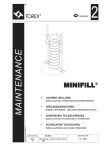

![004770261 [FR ES CS] Clemy v.112008.indd](http://vs1.manualzilla.com/store/data/006249672_1-daca7f6fa5abc2361083fd286bd3fe4f-150x150.png)