1
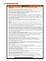
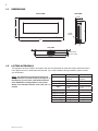
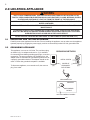
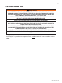
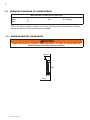
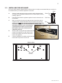
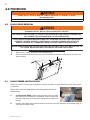
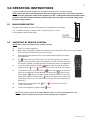
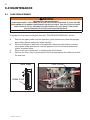
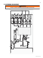
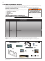
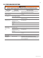
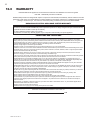
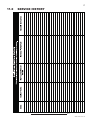
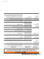
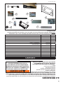
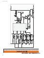
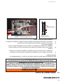
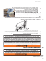
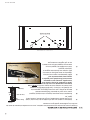
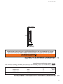
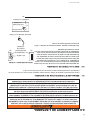
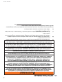
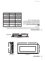
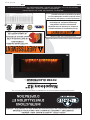
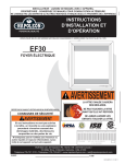
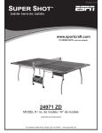
INSTALLER: LEAVE THIS MANUAL WITH THE APPLIANCE.
CONSUMER: RETAIN THIS MANUAL FOR FUTURE REFERENCE.
NEVER LEAVE CHILDREN OR OTHER AT RISK INDIVIDUALS ALONE WITH THE APPLIANCE.
1
INSTALLATION AND
OPERATING INSTRUCTIONS
CERTIFIED UNDER CANADIAN AND AMERICAN NATIONAL STANDARDS: CSA C22.2 No-46 / UL 1278
Napoleon 42"
ELECTRIC FIREPLACE
!
WARNING
HOT GLASS WILL CAUSE
BURNS.
CERTIFIED FOR CANADA AND UNITED STATES USING ANSI/CSA METHODS.
SAFETY INFORMATION
!
WARNING
DO NOT TOUCH GLASS UNTIL
COOLED.
NEVER ALLOW CHILDREN TO
TOUCH GLASS.
If the information in these instructions are
not followed exactly, a fire or explosion
may result causing property damage,
personal injury or loss of life.
- Do not store or use gasoline or other flammable
vapors and liquids in the vicinity of this or any
other appliance.
Wolf Steel Ltd., 24 Napoleon Rd., Barrie, ON, L4M 0G8 Canada /
103 Miller Drive, Crittenden, Kentucky, USA, 41030
Phone (705)721-1212 • Fax (705)722-6031 • www.napoleonfireplaces.com • [email protected]
$10.00
1.16B
W415-1134 / 07.04.12
2
TABLE OF CONTENTS
1.0
2.0
3.0
4.0
5.0
6.0
INTRODUCTION
3
1.1
1.2
1.3
4
4
5
LOCATING APPLIANCE
6
2.1
2.2
6
6
UNPACKING AND TESTING APPLIANCE
GROUNDING APPLIANCE
INSTALLATION
7
3.1
3.2
3.3
8
8
9
MINIMUM CLEARANCE TO COMBUSTIBLES
MINIMUM MANTEL CLEARANCES
INSTALLING THE APPLIANCE
FINISHING
10
4.2
4.1
10
10
GLASS DOOR REMOVAL
GLASS EMBER INSTALLATION
OPERATING INSTRUCTIONS
11
5.1
5.2
11
11
MAIN POWER SWITCH
OPERATING BY REMOTE CONTROL
MAINTENANCE
6.1
7.0
8.0
9.0
10.0
11.0
12.0
DIMENSIONS
LISTING APPROVALS
GENERAL INSTRUCTIONS
FUSE REPLACEMENT
WIRING DIAGRAM
REPLACEMENT PARTS
TROUBLESHOOTING
WARRANTY
SERVICE HISTORY
NOTES
NOTE: Changes, other than editorial, are denoted by a vertical line in the margin.
W415-1134 / 07.04.12
12
12
13
14
15
16
17
18
3
1.0 INTRODUCTION
!
•
•
•
•
•
•
•
•
•
•
•
•
•
•
•
•
•
•
•
•
•
•
•
•
•
•
•
•
•
WARNING
THIS APPLIANCE IS HOT WHEN OPERATED AND CAN CAUSE SEVERE BURNS IF
CONTACTED.
Do not operate appliance before reading and understanding operating instructions. Failure to operate
appliance according to operating instructions could cause fire or injury.
Risk of burns. Power to the appliance should be turned off and the appliance allowed to cool before
servicing. To disconnect power to the appliance, turn controls to off, then remove plug from outlet.
Do not install damaged, incomplete or substitute components.
Do not burn wood or other materials in this appliance.
Young children should be carefully supervised when they are in the same room as the appliance.
Toddlers, young children and others may be susceptible to accidental contact burns. A physical barrier
is recommended if there are at risk individuals in the house. To restrict access to an appliance or stove,
install an adjustable safety gate to keep toddlers, young children and other at risk individuals out of the
room and away from hot surfaces.
Clothing or other flammable material should not be placed on or near the appliance.
Due to high temperatures, the appliance should be located out of traffic and away from furniture and
draperies.
Ensure you have incorporated adequate safety measure to protect infants/toddlers from touching hot
surfaces.
Even after the appliance is out, the glass and/or screen will remain hot for an extended period of time.
Check with your local hearth specialty dealer for safety screens and hearth guards to protect children
from hot surfaces. These screens and guards must be fastened to the floor.
Any safety screen or guard removed for servicing must be replaced prior to operating the appliance.
It is imperative that the control compartments, circulating blower and its passageway in the appliance
and are kept clean. The appliance should be inspected before use and at least annually by a qualified
service person. More frequent cleaning may be required due to excessive lint from carpeting, bedding
material, etc. The appliance area must be kept clear and free from combustible materials, gasoline and
other flammable vapors and liquids.
Under no circumstances should this appliance be modified.
Do not use this appliance if any part has been under water. Immediately call a qualified service technician
to inspect the appliance and to replace any part of the control system which has been under water.
Do not operate the appliance with the glass door removed, cracked or broken. Replacement of the
glass should be done by a licensed or qualified service person.
Do not strike or slam shut the appliance glass door.
Keep the packaging material out of reach of children and dispose of the material in a safe manner. As
with all plastic bags, these are not toys and should be kept away from children and infants.
Servicing should be done only while the appliance is disconnected from the power supply circuit.
Always unplug appliance when not in use.
Do not operate this appliance with a damaged cord or plug after the appliance malfunctions, has been
dropped or damaged in any manner. Return appliance to authorized service facility for examination,
electrical or mechanical adjustment, or repair.
Do not use outdoors.
Never locate appliance where it may fall into a bathtub or other water container.
Do not run cord under carpeting. Do not cover cord with throw rugs, runners, or the like. Arrange cord
away from traffic area and where it will not be tripped over.
Connect to properly grounded outlets only.
Do not insert or allow foreign objects to enter any ventilation or exhaust opening as this may cause an
electric shock or fire, or damage the appliance.
To prevent a possible fire, do not block air intakes or exhaust in any manner. Do not use on soft
surfaces, like a carpet, where openings may become blocked.
Always plug appliances directly into a wall outlet/receptacle. Never use an extension cord or
relocatable power tap (outlet/power strip).
Ensure clearances to combustibles are maintained when building a mantel or shelves above the
appliance. Elevated temperatures on the wall or in the air above the appliance can cause melting,
discolouration or damage to decorations, a T.V. or other electronic components.
3.7C
W415-1134 / 07.04.12
4
1.1
DIMENSIONS
FRONT VIEW
SIDE VIEW
4 5/8”
18”
17”
Power
Switch
42”
TOP VIEW
Heat Vents
(Do not cover)
35 1/2”
1.2
LISTING APPROVALS
This appliance has been tested in accordance with the CSA Standards for fixed and location-dedicated electric
room appliances in the United States and Canada. If you need assistance during installation, please contact
your local dealer.
Model Number
NOTE: This appliance must be electrically wired
and grounded in accordance with local codes or, in
the absence of local codes, with National Electric
Code ANSI/NFPA 70-latest edition in the United
States or the Canadian Electric Code, CSA C22.1 in
Canada.
EFL42
NLF42
Wall-Mount
Appliance
Wall-Mount
Appliance
120V AC
120V AC
Watts
Max 1500W
Max 1500W
Amps
15 AMP Grounded
Circuit
15 AMP Grounded
Circuit
42"
42"
Appliance Height 18"
18"
Appliance Depth
4 5/8"
4 5/8"
Net Weight
20.5 Kg
20.5 Kg
Gross Weight
27.5 Kg
27.5 Kg
Description
Voltage
Appliance Width
W415-1134 / 07.04.12
5
1.3
GENERAL INSTRUCTIONS
!
WARNING
READ THESE INSTRUCTIONS COMPLETELY BEFORE BEGINNING INSTALLATION. FAILURE TO
FOLLOW THEM COULD CAUSE AN APPLIANCE MALFUNCTION RESULTING IN SERIOUS INJURY
AND/OR PROPERTY DAMAGE.
ALL ELECTRIC APPLIANCES HAVE HOT AND ARCING OR SPARKING PARTS INSIDE. DO NOT USE
IT IN AREAS WHERE GASOLINE, PAINT OR FLAMMABLE LIQUIDS ARE PRESENT.
THIS ELECTRIC APPLIANCE IS TESTED AND LISTED FOR USE ONLY WITH THE OPTIONAL
ACCESSORIES LISTED IN THESE INSTRUCTIONS. USE OF OPTIONAL ACCESSORIES NOT
SPECIFICALLY TESTED FOR THIS ELECTRIC APPLIANCE COULD VOID THE WARRANTY AND/OR
RESULT IN A SAFETY HAZARD.
DO NOT OPEN. RISK OF ELECTRIC SHOCK. NO USER-SERVICEABLE PARTS INSIDE.
DO NOT USE DAMAGED ELECTRICAL CORDS.
SERVICING SHOULD BE DONE ONLY WHILE THE APPLIANCE IS DISCONNECTED FROM THE
POWER SUPPLY CIRCUIT.
HIGH TEMPERATURE, RISK OF FIRE. KEEP ELECTRICAL CORDS, DRAPERY, FURNISHINGS, AND
OTHER COMBUSTIBLES AT LEAST 3 FEET (0.9M) FROM THE FRONT OF THE APPLIANCE AND
AWAY FROM SIDES AND REAR.
TO PREVENT ELECTRIC SHOCK MATCH THE WIDE BLADE OF PLUG TO WIDE SLOT OF
RECEPTACLE AND FULLY INSERT.
A.
Prior to plugging your appliance into an electrical outlet, verify that the house circuit breakers for the
outlet are on.
B.
The appliance may emit a slight, harmless odour when first used. This odour is normal and it is caused
by the initial heating of internal appliance elements and will not occur again.
C.
If your appliance does not emit heat, consult the operation section of this manual for further
information.
D.
Use with a CSA or UL certified surge protector.
This electric appliance meets the construction and safety standards of H.U.D. for application in manufactured
homes when installed according to these instructions.
4.8
W415-1134 / 07.04.12
6
2.0 LOCATING APPLIANCE
!
WARNING
DUE TO HIGH TEMPERATURES, THIS ELECTRIC APPLIANCE SHOULD BE LOCATED OUT OF
TRAFFIC. KEEP COMBUSTIBLE MATERIALS SUCH AS FURNITURE, PILLOWS, BEDDING, PAPERS,
CLOTHES AND CURTAINS AT LEAST 36" FROM THE FRONT OF THE APPLIANCE.
NEVER LOCATE THIS ELECTRIC APPLIANCE WHERE IT MAY FALL INTO A BATHTUB OR OTHER
WATER CONTAINER.
WEAR SAFETY GLOVES AND SAFETY GLASSES FOR PROTECTION DURING INSTALLATION AND
MAINTENANCE.
TO PREVENT CONTACT WITH SAGGING OR LOOSE INSULATION, THE ELECTRIC APPLIANCE
MUST NOT BE INSTALLED AGAINST VAPOR BARRIER OR EXPOSED INSULATION. LOCALIZED
OVERHEATING COULD OCCUR AND A FIRE COULD RESULT.
DO NOT EXPOSE THE ELECTRIC APPLIANCE TO THE ELEMENTS (SUCH AS RAIN, ETC.)
2.1
UNPACKING AND TESTING APPLIANCE
Carefully remove the appliance from the box. Prior to installing the appliance, test to make sure the appliance
operates properly by plugging the power supply cord into a conveniently located 120 Volt grounded outlet.
2.2
GROUNDING APPLIANCE
This appliance is for use on 120 Volts. The cord has a plug
as shown in (A). An adapter as shown in (C) is available
for connecting three-blade grounding type plugs to two-slot
receptacles. The green grounding lug extending from the
adapter must be connected to a permanent ground such as
a properly grounded outlet box. The adapter should not be
used if a three-slot grounded receptacle is available.
To disconnect appliance, turn controls to off, then remove
plug from outlet.
GROUNDING METHODS
METAL SCREW
COVER OF
GROUNDED
OUTLET BOX
(A)
GROUNDING PIN
ADAPTER
(C)
GROUNDING
MEANS
NOT ALLOWED IN CANADA
96.1
W415-1134 / 07.04.12
(B)
7
3.0 INSTALLATION
!
WARNING
RISK OF FIRE! THE POWER CORD MUST NOT BE PINCHED AGAINST A SHARP EDGE. SECURE CORD TO AVOID
TRIPPING OR SNAGGING TO REDUCE THE RISK OF FIRE, ELECTRIC SHOCK OR PERSONAL INJURY. DO NOT RUN
CORD UNDER CARPETING. DO NOT COVER CORD WITH THROW RUGS, RUNNERS OR THE LIKE. ARRANGE CORD
AWAY FROM TRAFFIC AREAS AND WHERE IT WILL NOT BE TRIPPED OVER.
RISK OF FIRE! TO PREVENT A POSSIBLE FIRE, DO NOT BLOCK AIR INTAKE OR EXHAUST IN ANY MANNER. DO NOT
USE ON SOFT SURFACES WHERE OPENINGS MAY BECOME BLOCKED.
RISK OF FIRE! DO NOT BLOW OR PLACE INSULATION AGAINST THE APPLIANCE.
THIS ELECTRIC APPLIANCE IS TESTED AND LISTED FOR USE ONLY WITH THE APPROVED OPTIONAL ACCESSORIES.
USE OF OPTIONAL ACCESSORIES NOT SPECIFICALLY TESTED FOR THIS ELECTRIC APPLIANCE COULD VOID THE
WARRANTY AND/OR RESULT IN A SAFETY HAZARD.
IF THE INFORMATION IN THESE INSTRUCTIONS IS NOT FOLLOWED EXACTLY, A FIRE OR EXPLOSION MAY RESULT
CAUSING PROPERTY DAMAGE, PERSONAL INJURY OR DEATH. DO NOT STORE OR USE GASOLINE OR OTHER
FLAMMABLE VAPORS IN THE VICINITY OF THIS OR ANY OTHER APPLIANCE.
THIS APPLIANCE IS HEAVY. IT IS HIGHLY RECOMMENDED THAT TWO PEOPLE INSTALL THIS APPLIANCE.
HEATER VENTS ON THE ELECTRIC APPLIANCE CANNOT, IN ANY WAY, BE COVERED AS IT MAY CREATE A FIRE
HAZARD.
68.5
Your EFL42/NLF42 is a wall-mounted appliance. Select a suitable location that is not susceptible to moisture
and is away from drapes, furniture and high traffic areas. NOTE: Follow all National and local electrical
codes.
W415-1134 / 07.04.12
8
3.1
MINIMUM CLEARANCE TO COMBUSTIBLES
Measurements are taken from the glass front.
Bottom
0"
Top
8" to mantel
Sides
0"
Top
8" to ceiling
Back
0"
NOTE: The power switch is located on the lower right hand side of the appliance. Always
ensure that access to this switch remains available.
3.2
MINIMUM MANTEL CLEARANCES
!
WARNING
WHEN USING PAINT OR LACQUER TO FINISH THE MANTEL, THE PAINT OR LACQUER MUST BE
HEAT RESISTANT TO PREVENT DISCOLOURATION.
Mantel
8”
Wall
Floor
Side View
W415-1134 / 07.04.12
9
3.3
INSTALLING THE APPLIANCE
Due to the many different materials used on different walls, it is highly recommended that you consult your
local builder before you install this appliance on the wall.
Body
A.
Select a location that is not prone to moisture and is located at least
36" away from combustible materials such as curtain drapes, furniture,
bedding, paper, etc.
Glass Front
B.
Have two people hold the appliance against the wall to determine the
final location.
Side View
C.
Mark out location, then mount the bracket onto the wall using the six
Floor
supplied screws. This bracket MUST have the hooks facing upward
and be level. NOTE: It is strongly recommended that the mounting
bracket be screwed into the wall studs where possible. If the
wall studs cannot be used, ensure that the
Screws
supplied plastic anchors are used to affix
the bracket to the wall and the bracket is
adequately secured.
D.
With the wall mounting bracket installed have two
people lift the appliance up and insert the two
hooks on the bracket into the two slots on the
back of the appliance.
E.
Check the appliance for stability ensuring that the
bracket will not pull free from the wall.
Hooks
18”
MIN
Wall Mount
Bracket
REAR VIEW
SLOTS
W415-1134 / 07.04.12
10
4.0 FINISHING
!
WARNING
POWER SUPPLY SERVICE MUST BE COMPLETED PRIOR TO FINISHING TO AVOID
RECONSTRUCTION.
HEAT VENTS AND AIR OPENINGS CANNOT BE COVERED IN ANY CIRCUMSTANCES.
4.2
GLASS DOOR REMOVAL
!
WARNING
GLASS MAY BE HOT, DO NOT TOUCH GLASS UNTIL COOLED.
THE DOOR LATCHES ARE PART OF A SAFETY SYSTEM AND MUST BE PROPERLY ENGAGED. DO
NOT OPERATE THE APPLIANCE WITH LATCHES DISENGAGED.
FACING AND/OR FINISHING MATERIALS MUST NOT INTERFERE WITH AIR FLOW THROUGH AIR
OPENINGS, LOUVRES OPENINGS, OPERATION OF LOUVRES OR DOORS OR ACCESS FOR
SERVICE. OBSERVE ALL CLEARANCES WHEN APPLYING COMBUSTIBLE MATERIALS.
BEFORE DOOR IS REMOVED TURN THE APPLIANCE OFF AND WAIT UNTIL APPLIANCE IS COOL TO
THE TOUCH. DOORS ARE HEAVY AND FRAGILE SO HANDLE WITH CARE.
75.1
4.1
A.
Remove the 7 screws, as shown in the illustration below.
B.
Tilt the top of the door forward until you can hold the sides of the door. Lift the door up and out of the
bottom retainer.
GLASS EMBER INSTALLATION
Glass front must be removed and the appliance must be mounted in its final location before the glass embers
are installed.
Glass embers may have sharp edges, wear safety glasses and gloves
when handling.
A.
CLEAN GLASS MEDIA: Glass media may have a fine oil residue
that needs to be cleaned prior to installation. Clean the glass with
mild dish soap, drain, rinse thoroughly and dry before placing into
the tray.
B.
Carefully place glass embers into the bottom tray on the front of the appliance as illustrated. Apply an
even layer from side to side.
W415-1134 / 07.04.12
11
5.0 OPERATING INSTRUCTIONS
Once the appliance has been plugged into a grounded electrical outlet, it is ready to operate.
NOTE: Ensure the house circuit breakers for the power supply are turned on. In the event of a power
failure, when the main power switch of the appliance is in the "I" ON position and the hand held remote
control is in the OFF position, the flame generation lights will come back on at the high setting, when
the power supply returns.
5.1
MAIN POWER SWITCH
The Main Power Switch is located on the right side of the appliance as illustrated.
The "|" indicates ON and "O" indicates OFF. Push the switch to "|" to turn
on the appliance and the flame effect.
POWER
SWITCH
5.2
OPERATING BY REMOTE CONTROL
NOTE: Make certain new batteries are installed correctly.
A.
Plug in your electric appliance.
B.
Make certain the appliance’s Main Power Switch is at the ON position! The remote control will NOT
work if the Main Power Switch is at the OFF position.
C.
When operating the remote control, it must be directed towards the front center
of the appliance.
D.
The
button at the top left of the remote can be used to power up or down the
appliance (the main power switch on the appliance must be in the ON position for
the remote to operate). Pressing this button activates the power to the appliance.
E.
button and then to adjust the flame
To activate flame, press the "FLAME"
height press the “ +5” or “
-5” buttons. There are five levels of flame effects.
F.
To activate the heater, press the "HEAT"
button. The initial set-up heat level
will be set for high heat, to adjust the heat level choose the
button for high
heat (1500W) or button for low heat (750W). Adjusting to auto control by room
button, the heater turns on when room
temperature press the "ROOM TEMP"
temperature is below 21°C. the heater will turn off when the room temperature is
above 25°C.
G.
To adjust the blue flame press the “
levels of flame effects.
H.
To turn off the appliance, press the button
+5” or “
-5” buttons. There are five
once.
NOTE: This remote control must remain within 8 meters or 26 feet of the appliance to be
effective and this range may be reduced as the battery power is depleted.
W415-1134 / 07.04.12
12
6.0 MAINTENANCE
6.1
FUSE REPLACEMENT
!
WARNING
PREPARATION FOR MAINTENANCE
ALWAYS DISCONNECT THE POWER AND ALLOW THE ELECTRIC APPLIANCE TO COOL BEFORE
PERFORMING ANY CLEANING, MAINTENANCE OR RELOCATION OF THIS ELECTRIC APPLIANCE.
TURN CONTROLS TO OFF AND REMOVE PLUG FROM OUTLET OR TURN OFF THE HOUSE
CIRCUIT BREAKER TO ELECTRIC APPLIANCE RECEPTACLE.
DO NOT INSTALL REPLACEMENT LAMPS THAT EXCEED SPECIFIED MAXIMUM WATTS.
To replace the fuse remove the glass door see "GLASS DOOR REMOVAL" section.
A.
B.
C.
D.
Remove the glass media from the appliance, glass embers may have sharp edges,
wear safety glasses and gloves when handling.
Remove 4 screws on each side of the appliance that secure the firebox front and
mirror glass holder and remove from the appliance, the circuit board will become
visible, as shown below
Remove the mirror glass prior to accessing the circuit board.
Remove the fuse cover to gain access to the fuse and replace the existing fuse with
the new fuse.
Side View
Glass Front
W415-1134 / 07.04.12
FUSE COVER
L1
N
P-SW
F1
N 6.3*0.8
FUSE2
HS0038
PTC
R6
10K
t
+5V
t130
F2
TRANS1
230V,120V/12V
6.3*0.58
PH-6
6.3*0.8
P-L
C6
BUZ1
4
TEMP
+5V
C8
104
5v
2.4*2
1
2
2
C1
10K
R14
SS8050
T4
470U/35V
D1~D4
1N4007 *4
1K
R9
2.4*7
1
2
3
4
5
6
SIP2
510
R8
D9
4007
C2
104(独独)
+12V
10K
R15
C7
104
100/0.5W
R20
1
P5.3
P5.2
11
P0.4
P4.2/AIN2
P4.1/AIN1
Vout
7805
12
C9
104 5
16
15
2 P0.1
Vin
IC1
3
C4
20
VDD
104
SN8P2722
1KU/16V
C3
+5V
VSS
10
P5.1
P5.0
P0.7
P0.5
P0.6
P0.2
510
10 R5
510
9 R4
510
8 R2
6
7
3
T3
8050
8050
T2
T1
8050
1N4007
+12V
1N4007
+12V
1N4007
+12V
100
R?
180
100
R?
100
180
R?
180
R?
D7
D6
D5
LED7
LED5
LED7
LED5
MOTOR
6.3*0.8
1
2
1
2
H1
2.4*2 2.4*2
1
2
T7
SS8050
T8
SS8050
PH-4
6.3*0.8
T6
SS8050
LED-M LAMP +12V
2.4*2 2.4*2
1
2
LED-HB FIRE-Y +12V
MOTOR
H2
1
2
2.4*2 2.4*2
1
2
LED-HY FIRE-B +12V
FAN MOTOR
510
510
R7
RELAY-MOTOR
6.3*0.8
H2 PH-2
RELAY-H2
6.3*0.8
H1+FAN
RELAY-H1
510
R1
LED8
LED6
R3
LED8
LED6
LED3
DS?
DS?
LED2
LED1
LED0
!
P-NI
6.3*0.8
TEMP_BRK
1
3
PH-7
25*C,5K
THERMI STOR
GND
2
S1
13
7.0 WIRING DIAGRAM
ENSURE ALL POWER IS TURNED OFF BEFORE HARD WIRING THIS APPLIANCE.
WARNING
W415-1134 / 07.04.12
25V 47uF
14
8.0 REPLACEMENT PARTS
Contact your dealer or the factory for questions concerning prices and policies on replacement parts. Normally
all parts can be ordered through your Authorized dealer / distributor.
FOR WARRANTY REPLACEMENT PARTS, A PHOTOCOPY OF THE ORIGINAL INVOICE WILL BE
REQUIRED TO HONOUR THE CLAIM.
When ordering replacement parts always give the following information:
• Model & Serial Number of appliance
• Installation date of appliance
• Part number
• Description of part
• Finish
* IDENTIFIES ITEMS WHICH ARE NOT ILLUSTRATED. FOR
FURTHER INFORMATION, CONTACT YOUR AUTHORIZED DEALER.
!
WARNING
FAILURE TO POSITION THE PARTS
IN ACCORDANCE WITH THIS
MANUAL OR FAILURE TO USE ONLY
PARTS SPECIFICALLY APPROVED
WITH THIS APPLIANCE MAY
RESULT IN PROPERTY DAMAGE OR
PERSONAL INJURY.
41.1
For aftermarket sales and service please call 1-866-539-2039
COMPONENTS
REF NO.
PART NO.
DESCRIPTION
1
W405-0008
LED CIRCUIT BOARD FOR EMBER BED
2
W190-0050
CIRCUIT BOARD
3
W062-0047
BLOWER AND HEATER ASSEMBLY
4
W660-0128
SWITCH (RK1-11)
5
W190-0051
REMOTE CONTROL
6
W300-0155
FRONT GLASS
7
W300-0156
MIRROR GLASS
8
W707-0016
TRANSFORMER
9
W010-2918
DRUM ASSEMBLY
10
W660-0129
REMOTE RECEIVER
11*
W300-0157
GLASS CHIP
12*
W435-0055
120V 30/36RPM
13
W080-1282
BRACKET
14
W285-0006
FUSE
NOTE: Care must be taken when removing and disposing of any broken glass or damaged
components. Be sure to vacuum up any broken glass from inside the appliance before operation.
4
1
-5 OFF
+5 MAX
FLAME
HEAT
HIGH
3
-5 OFF
LOW
TEMP
+5 MAX
5
BLUE LIGHT
7
9
2
8
10
6
14
13
W415-1134 / 07.04.12
15
9.0 TROUBLESHOOTING
!
WARNING
TURN OFF THE APPLIANCE COMPLETELY AND LET COOL BEFORE SERVICING. ONLY A
QUALIFIED SERVICE PERSON SHOULD SERVICE AND REPAIR THIS ELECTRIC APPLIANCE.
SYMPTOM
PROBLEM
TEST SOLUTION
Dim or no flame
Drum LED’s are burnt out
Inspect the LED’s inside the flame generation cylinder drum
(W010-2918) and replace them if necessary
Ember bed is not
glowing or dimming
Ember LED’s are burnt out
Inspect the ember bed LED’s (W405-0008) and replace them if
necessary
No warm air coming
out of appliance
Room temperature is higher
than the appliance setting (if
it is set to room temperature)
Set the appliance to a high or low heat setting.
Heater is burnt out
Inspect the burner and heater assembly (W062-0047) and
replace it if necessary
Appliance has overheated
and safety device has
caused the thermal switch to
disconnect
Unplug the appliance, allow appliance to cool for 15 minutes,
then plug it back in
House circuit breaker has
tripped
Reset house circuit breaker
Appliance’s fuse has blown
Replace the fuse
Appliance is not plugged into
an electrical outlet
Check plug and plug it in
Appliance has overheated
and safety device has
caused the thermal switch to
disconnect
Unplug the appliance, allow appliance to cool for 15 minutes,
then plug it back in
Circuit board is burnt out
Inspect the circuit board (W190-0050) and replace it if
necessary
Remote control
does not work
Low batteries
Replace batteries in remote control
Heater shuts off
automatically
Room is too warm
The heater has a built-in thermostat so it will shut off
automatically once the pre-set temperature is reached. It will
also turn on automatically if the room temperature drops below
the pre-set temperature
Appliance turns off
and will not turn on
Appliance will not
come on when
switch is flipped to
ON
W415-1134 / 07.04.12
16
10.0
WARRANTY
NAPOLEON® electric appliances are manufactured under the strict Standard of the world recognized
ISO 9001 : 2008 Quality Assurance Certificate.
NAPOLEON® products are designed with superior components and materials, assembled by trained craftsmen who take
great pride in their work. Once assembled the complete appliance is thoroughly inspected by a qualified technician before
packing to ensure that you , the customer, receive the quality product that you expect from NAPOLEON®.
NAPOLEON® ELECTRIC APPLIANCE LIMITED WARRANTY
Electrical components and wearable parts such as fan/heater, motors, switches, nylon bearing components and remote
controls are covered and NAPOLEON® will provide replacement parts free of charge during the first year of limited warranty.
Light bulbs and fuses are NOT covered by the warranty.
Any labour related to warranty repair is not covered.
* Construction of models vary. Warranty applies only to components included with your specific appliance.
CONDITIONS AND LIMITATIONS
NAPOLEON® warrants its products against manufacturing defects to the original purchaser only. Registering your warranty is not necessary.
Simply provide your proof of purchase along with the model and serial number to make a warranty claim. NAPOLEON® reserves the right to have
its representative inspect any product or part thereof prior to honouring any warranty claim. Provided that the purchase was made through an
authorized NAPOLEON® dealer your appliance is subject to the following conditions and limitations:
Warranty coverage begins on the date of original installation.
This factory warranty is non-transferable and may not be extended whatsoever by any of our representatives.
Installation must be done in accordance with the installation instructions included with the product and all local and national building and fire codes.
This limited warranty does not cover damages caused by misuse, lack of maintenance, accident, alterations, abuse or neglect and parts installed
from other manufacturers will nullify this warranty.
This limited warranty further does not cover any scratches, dents, corrosion or discoloring caused by excessive heat, abrasive and chemical
cleaners nor chipping on porcelain enamel parts, mechanical breakage of PHAZER™ logs.
In the first year only, this warranty extends to the repair or replacement of warranted parts which are defective in material or workmanship provided
that the product has been operated in accordance with the operation instructions and under normal conditions.
NAPOLEON® will not be responsible for installation, labour or any other expenses related to the reinstallation of a warranted part and such
expenses are not covered by this warranty. Notwithstanding any provisions contained in the Limited Warranty, NAPOLEON’s responsibility under
this warranty is defined as above and it shall not in any event extend to any incidental, consequential or indirect damages.
This warranty defines the obligations and liability of NAPOLEON® with respect to the NAPOLEON® electric appliance and any other warranties
expressed or implied with respect to this product, its components or accessories are excluded.
NAPOLEON® neither assumes, nor authorizes any third party to assume, on its behalf, any other liabilities with respect to the sale of this product.
Any damages to appliance, brass trim or other component due to water, weather damage, long periods of dampness, condensation, damaging
chemicals or cleaners will not be the responsibility of NAPOLEON®.
The bill of sale or copy will be required together with a serial number and a model number when making any warranty claims from your authorized
dealer. The warranty registration card must be returned within fourteen days to register the warranty.
NAPOLEON® reserves the right to have its representative inspect any product or part thereof prior to honouring any warranty claim.
All parts replaced under the Limited Warranty Policy are subject to a single claim.
All parts replaced under the warranty will be covered for a period of 90 days from the date of their installation.
The manufacturer may require that defective parts or products be returned or that digital pictures be provided to support the claim. Returned
products are to be shipped prepaid to the manufacturer for investigation. If a product is found to be defective, the manufacturer will repair or
replace such defect.
Before shipping your appliance or defective components, your dealer must obtain an authorization number. Any merchandise shipped without
authorization will be refused and returned to sender.
Shipping costs are not covered under this warranty.
Additional service fees may apply if you are seeking warranty service from a dealer.
ALL SPECIFICATIONS AND DESIGNS ARE SUBJECT TO CHANGE WITHOUT PRIOR NOTICE DUE TO ON-GOING PRODUCT IMPROVEMENTS.
NAPOLEON® IS A REGISTERED TRADEMARK OF WOLF STEEL LTD.
2.5B
W415-1134 / 07.04.12
17
11.0
SERVICE HISTORY
43.1
W415-1134 / 07.04.12
18
12.0
NOTES
44.1
W415-1134 / 07.04.12
19
44.1
W415-1134 / 07.04.12
20
W415-1134 / 07.04.12
20
W415-1134 / 07.04.12
19
44.1
W415-1134 / 07.04.12
18
12.0
NOTES
44.1
W415-1134 / 07.04.12
Date
Détaillant
Historique d’entretien Wolf Steel
Problèmes particuliers
11.0
Travail effectué
Cet appareil doit être entretenu annuellement selon son usage.
Nom du technicien
43.1
W415-1134 / 07.04.12
HISTORIQUE D'ENTRETIEN
17
16
10.0
GARANTIE
Les foyers électriques NAPOLÉON® sont fabriqués conformément aux normes strictes du Certificat
d’Assurance de Qualité mondialement reconnu ISO 9001 : 2008.
Les produits NAPOLÉON® sont conçus avec des composants et des matériaux de qualité supérieure, assemblés par
des artisans qualifiés qui sont fiers de leur travail. Une fois assemblé, chaque foyer est soigneusement inspecté par un
technicien qualifié avant d’être emballé pour garantir que vous, le client, recevez le produit de qualité dont vous vous
attendez de NAPOLÉON®.
GARANTIE LIMITÉE DES APPAREILS ÉLECTRIQUES NAPOLÉON®
Les composants électriques et les pièces soumises à l’usure tels que la soufflerie/chaufferette, les moteurs, les
interrupteurs, les roulements à billes en nylon et les télécommandes sont couverts et NAPOLÉON® fournira
gratuitement les pièces de rechange durant la première année de la garantie limitée.
Les ampoules et les fusibles NE SONT PAS couverts par la garantie.
Les coûts de main-d’oeuvre relatifs aux réparations garanties ne sont pas couverts.
*La fabrication de chaque modèle varie. La garantie s’applique uniquement aux composants disponibles avec votre
appareil.
CONDITIONS ET LIMITATIONS
NAPOLÉON® garantit ses produits contre les défauts de fabrication à l’acheteur d’origine seulement. L’enregistrement de la garantie
n’est pas nécessaire. Fournissez simplement une preuve d’achat ainsi que le modèle et le numéro de série afin d’effectuer une
réclamation de garantie. Napoléon® se réserve le droit de demander à son représentant d’inspecter tous produits ou pièces avant
d’honorer toute réclamation. L’achat doit avoir été fait par l’entremise d’un détaillant NAPOLÉON® autorisé et sous réserve des
conditions et limitations suivantes :
La couverture de la garantie débute à partir de la date d’installation originale.
Cette garantie du fabricant n’est pas transférable et ne peut être prolongée ou étendue par aucun de nos représentants quelle qu’en
soit la raison.
L’installation doit être faite conformément aux instructions d’installation incluses avec le produit et à tous les codes d’incendie et de
construction locaux et nationaux.
Cette garantie limitée ne couvre pas les dommages causés par un mauvais usage, un manque d’entretien, un accident, des altérations,
des abus ou de la négligence, et l’installation de pièces d’autres fabricants annulera cette garantie.
Cette garantie limitée ne couvre pas non plus les égratignures, les bossellements, la corrosion ou la décoloration causée par
une chaleur excessive, des produits d’entretien chimiques et abrasifs ou l’écaillage de pièces en porcelaine émaillée, le bris par
manipulation des bûches Phazer®.
Au cours de la première année seulement, cette garantie s’étend à la réparation ou au remplacement des pièces garanties dont les
matériaux ou la fabrication sont défectueux à la condition que le produit ait été utilisé conformément aux instructions de fonctionnement
et dans des conditions normales.
NAPOLÉON® ne sera pas responsable de l’installation, de la main-d’oeuvre ou autres coûts ou dépenses relatives à la réinstallation
d’une pièce garantie, et de telles dépenses ne sont pas couvertes par cette garantie. Nonobstant toutes les dispositions contenues
dans cette Garantie Limitée, la responsabilité de NAPOLÉON® sous cette garantie est définie comme ci-dessus et elle ne s’étendra à
aucun dommage accidentel, consécutif ou indirect.
Cette garantie définit l’obligation et la responsabilité de NAPOLÉON® en ce qui concerne l’appareil électrique NAPOLÉON®. Toute
autre garantie énoncée ou implicite en ce qui concerne ce produit, ses composants ou accessoires est exclue.
NAPOLÉON® n’endosse, ni n’autorise aucun tiers à assumer en son nom, toutes autres responsabilités concernant la vente de ce
produit.
Tous dommages causés à l’appareil, aux garnitures en laiton ou autres composants par l’eau, les dommages causés par les
intempéries, de longues périodes d’humidité, la condensation, des produits chimiques ou produits d’entretien nuisibles ne seront pas la
responsabilité de NAPOLÉON®.
La facture ou sa copie sera requise ainsi que le numéro de série et le numéro de modèle lors d’une réclamation auprès de votre
détaillant autorisé. La carte d’enregistrement de garantie doit être retournée dans les quatorze jours pour enregistrer la garantie.
NAPOLÉON® se réserve le droit de demander à son représentant d’inspecter tout produit ou pièce avant d’honorer toute réclamation.
Toutes les pièces remplacées en vertu de la politique de Garantie limitée ne peuvent faire l’objet que d’une seule réclamation.
Toutes les pièces remplacées au titre de la garantie seront couvertes pour une période de 90 jours à partir de leur date d’installation.
Le fabricant peut exiger que les pièces défectueuses ou les produits soient retournés ou que des photos numériques soient fournies pour valider la
réclamation. Les produits retournés doivent être expédiés port payé au fabricant pour une inspection en usine. Si un produit est déclaré défectueux,
le fabricant le réparera ou le remplacera.
Avant d’expédier votre appareil ou les pièces défectueuses, votre détaillant doit obtenir un numéro d’autorisation. Toute marchandise expédiée à
notre usine sans autorisation sera refusée et retournée à l’expéditeur.
Les coûts d’expédition ne sont pas couverts par cette garantie.
Des frais de service supplémentaires peuvent être appliqués si vous cherchez à obtenir des services au titre de la garantie auprès d’un détaillant.
TOUTES LES SPÉCIFICATIONS ET LES CONCEPTIONS SONT SUJETTES À MODIFICATIONS SANS PRÉAVIS EN RAISON DES
AMÉLIORATIONS CONSTANTES APPORTÉES AUX PRODUITS. NAPOLÉON® EST UNE MARQUE DE COMMERCE DÉPOSÉE DE
WOLF STEEL LTÉE.
2.5B
W415-1134 / 07.04.12
15
9.0 GUIDE DE DÉPANNAGE
!
AVERTISSEMENT
COUPEZ L’ALIMENTATION ÉLECTRIQUE À L’APPAREIL ET LAISSEZ-LE REFROIDIR AVANT
D’EFFECTUER UN ENTRETIEN. SEUL UN TECHNICIEN DE SERVICE QUALIFIÉ PEUT
EFFECTUER L’ENTRETIEN OU LA RÉPARATION DE CET APPAREIL.
SYMPTÔME
PROBLÈME
Braise DEL sont brûlées
Le lit de braises ne
s’illumine pas ou
ne diminue pas en
luminosité
Cylindre DEL sont brûlées
La luminosité du
jeu de flammes est
faible ou inexistante
SOLUTIONS
Vérifiez les DEL à l’intérieur du cylindre de création du jeu de
flammes (W010-2918) et remplacez-les au besoin
Vérifiez que les braises DEL et remplacez-les au besoin
Réinitialisez le disjoncteur
Le disjoncteur de
la maison s’est déclenché
Débranchez l'appareil, laissez-le refroidir pendant 10 minutes,
puis rebranchez-le
L'appareil a surchauffé et
le dispositif de sécurité a
entraîné le déclenchement
de l'interrupteur thermique
L’appareil s’éteint et
ne se rallume pas
Réglez l’appareil à une température plus élevée (MOYEN ou
ÉLEVÉ)
La température ambiante est
plus élevée que le réglage
de l’appareil (si réglée au
température du chambre)
L’appareil n’émet
aucune chaleur
Inspecter l’appareil de chauffage et l’assembler (W062-0047) et
remplacez-les au besoin
L’appareil de chauffage est
brûlé
La température ambiante
est trop élevée
La chaufferette
s'éteint automatiquement
Remplacez les piles AA de la télécommande
Les piles sont faibles
La télécommande
ne fonctionne pas
Inspecter la carte de circuit (W190-0050) et remplacez-les au
besoin
La carte de circuit est brûlé
Débranchez l'appareil, laissez-le refroidir pendant 10 minutes,
puis rebranchez-le
L'appareil a surchauffé et
le dispositif de sécurité a
entraîné le déclenchement
de l'interrupteur thermique
Vérifiez la fiche puis rebranchez-la
L'appareil n'est pas branché
dans une prise de courant
Remplacez le fusible
Le fusible de l’appareil a
sauté
L'appareil
ne s'allume
pas lorsque
l'interrupteur est mis
à « ON »
L'appareil est équipé d’un thermostat intégré et s’éteindra
automatiquement lorsque la température programmée sera
atteinte. Il s’allumera automatiquement lorsque la température de
la pièce descendra en dessous de la température programmée. La
température programmée dépend des réglages sélectionnés pour
la chaufferette
W415-1134 / 07.04.12
14
8.0 RECHANGES
Contactez votre détaillant ou le fabricant pour les questions concernant les prix et la disponibilité des pièces
de rechange. Normalement, toutes les pièces peuvent être commandées chez votre détaillant autorisé.
POUR UN REMPLACEMENT DE PIÈCE SOUS GARANTIE, UNE PHOTOCOPIE DE LA FACTURE ORIGINALE SERA REQUISE AFIN DE POUVOIR HONORER LA DEMANDE.
Lorsque vous commandez des pièces, donnez toujours
l’information suivante :
● Modèle et numéro de série de l’appareil
OMETTRE DE POSITIONNER LES PIÈCES
● Date d’installation de l’appareil
● Numéro de la pièce
CONFORMÉMENT AU MANUEL OU D’UTILISER
● Description de la pièce
UNIQUEMENT DES PIÈCES SPÉCIFIQUEMENT
● Fini
APPROUVÉES POUR CET APPAREIL PEUT
* IDENTIFIE LES ARTICLES QUI NE SONT PAS
CAUSER DES DOMMAGES MATÉRIELS
ILLUSTRÉS. POUR PLUS D’INFORMATION,
OU DES BLESSURES CORPORELLES.
CONTACTEZ VOTRE DÉTAILLANT AUTORISÉ.
!
AVERTISSEMENT
41.1
Pour le service après-vente, veuillez composer le 1-866-539-2039
COMPONENTS
W080-1282
13
W435-0055
12*
W300-0157
11*
W660-0129
10
W010-2918
9
W707-0016
8
W300-0156
7
W300-0155
6
W190-0051
5
W660-0128
4
W062-0047
3
W190-0050
2
W405-0008
1
PART NO.
REF NO.
W285-0006
14
DESCRIPTION
CARTE DE CIRCUIT DEL POUR LIT DE BRAISES
CARTE DE CIRCUIT
ASSEMBLAGE DE SOUFFLERIE ET DE CHAUFFERETTE
COMMUTATEUR (RK1-11)
TÉLÉCOMMANDE
FAÇADE VITRÉE
VERRE MIROIR
TRANSFORMATEUR
L'ASSEMBLER CYLINDRE
RÉCEPTEUR DE LA TÉLÉCOMMANDE
VERRE CONCASSÉ
120 V 30/36 TR/MIN
SUPPORT
FUSIBLE
NOTE: Usez de prudence lorsque vous enlevez et jetez des débris de verre ou des composants
endommagés. Assurez-vous d’aspirer tous les débris de verre à l’intérieur de l'appareil avant de le
faire fonctionner.
4
1
-5 OFF
FLAME
+5 MAX
HEAT
3
+5 MAX
-5 OFF
TEMP
HIGH
LOW
5
BLUE LIGHT
7
9
2
10
8
6
14
13
W415-1134 / 07.04.12
L1
N
PH-7
6.3*0.8
F1
FUSE2
PH-6
6.3*0.8
P-L
25V 47uF
6.3*0.58
230V,120V/12V
TRANS1
+5V
2
C1
10K
R14
SS8050
T4
470U/35V
D1~D4
1N4007 *4
4
BUZ1
TEMP
1
2
2.4*2
5v
C8
104
+12V
C2
104(独独)
D9
4007
R8
510
R9
1K
SIP2
1
2
3
4
5
6
2.4*7
R20
100/0.5W
C7
104
R15
10K
1
IC1
Vin
Vout
7805
P5.2
P5.3
P0.4
P4.2/AIN2
P4.1/AIN1
2 P0.1
15
16
C9
104 5
12
11
3
C3
1KU/16V
+5V
C4
104
20
VDD
SN8P2722
10
VSS
P0.2
P0.6
P0.5
P0.7
P5.0
P5.1
3
7
6
8 R2
510
9 R4
510
510
10 R5
T1
8050
8050
T2
T3
8050
R?
180
R?
180
100
R?
100
180
R?
100
+12V
1N4007
+12V
1N4007
+12V
1N4007
LED2
DS?
LED0
LED3
DS?
LED1
LED6
LED8
LED5
LED7
LED6
6.3*0.8
R7
510
1
2
1
2
T8
SS8050
LED-HY FIRE-B +12V
1
2
2.4*2 2.4*2
1
2
1
2
T7
SS8050
LED-HB FIRE-Y +12V
2.4*2 2.4*2
1
2
PH-4
6.3*0.8
T6
SS8050
LED-M LAMP +12V
2.4*2 2.4*2
H1
MOTOR
H2
FAN MOTOR
510
RELAY-MOTOR
6.3*0.8
H2 PH-2
RELAY-H2
6.3*0.8
H1+FAN
RELAY-H1
510
R1
LED8
R3
LED5
LED7
D5
D6
D7
MOTOR
!
R6
10K
t
+5V
t130
F2
TEMP_BRK
PTC
HS0038
C6
GND
2
1
3
S1
P-SW
P-NI
N 6.3*0.8
25*C,5K
THERMI STOR
W415-1134 / 07.04.12
ASSUREZ-VOUS QUE L'ALIMENTATION ÉLECTRIQUE EST COUPÉE AVANT D'EFFECTUER LE BRANCHEMENT PAR
CÂBLE DE CET APPAREIL.
AVERTISSEMENT
7.0 SCHÉMA DE CÂBLAGE
13
12
6.0 ENTRETIEN
6.1
REMPLACEMENT DE FUSIBLE
!
AVERTISSEMENT
PRÉPARATION POUR L'ENTRETIEN
DÉBRANCHEZ TOUJOURS L'ALIMENTATION ÉLECTRIQUE ET LAISSEZ L'APPAREIL REFROIDIR
AVANT DE LE NETTOYER, DE PROCÉDER À SON ENTRETIEN OU DE LE RELOCALISER. TOURNEZ
LES CONTRÔLES À « OFF » ET RETIREZ LA FICHE DE LA PRISE DE COURANT OU FERMEZ LE
DISJONCTEUR DU CIRCUIT DE VOTRE APPAREIL.
NE PAS INSTALLER D'AMPOULES DE RECHANGE QUI EXCÈDENT LA PUISSANCE (WATTS)
MAXIMALE SPÉCIFIÉE.
Pour remplacer la fusible enlever la porte vitrée voir la section « L'ENLÈVEMENT DU
PORTE VITRÉE ».
A.
B.
C.
D.
Enlever le médias verre de l'appareil, les braise de verre peut avoir des bords
tranchants, vous devriez porter les lunettes et les gants protectifs en contrôlant
la verre.
Enlever les 4 vis de chaque côté cela tient le devant de foyer et la verre miroir à
l'appareil, puis enlèver de l'appareil. La carte de circuit deviendra visible, comme
indiqué au dessous.
Enlever la verre miroir avant d'avoir accéder aux carte de circuit.
Enlever la couverture du fisible pour gagner l'accès au fusible, remplacer le fusible en
existance avec le nouveau fusible.
LA COUVERTURE DU FUSIBLE
Vue de côté
Face du vitre
W415-1134 / 07.04.12
11
5.0 INSTRUCTIONS DE FONCTIONNEMENT
L'appareil est prêt à fonctionner dès qu'il est correctement branché dans une prise de courant mise à la terre.
NOTE : Assurez-vous que les disjoncteurs de la maison pour ce circuit soient allumés. Lors d'une
panne de courant, quand l’interrupteur est à la position <"I" ON> et la télécommande soit à la position
<OFF> , la génération de flamme allumeera sur une réglant haut, quand l'alimentation électrique soient
en retours.
5.1
INTERRUPTEUR
L’interrupteur MARCHE/ARRÊT est situé au droite de l'appareil, comme illustré.
Le symbole « | » indique MARCHE et le symbole « O » indique ARRÊT. Pour
éteindre l'appareil et l'effet du flamme, placez l’interrupteur à la position « | ».
L'INTERRUPTEUR
5.2
UTILISATION DU PANNEAU DE CONTRÔLE
NOTE: Faire certain les nouveau piles sont correctement installées.
.
Pour éteindre l'appareil, appuyez une fois sur la touche
H.
+5 » ou «
Pour régler la flamme bleue, appuyez sur les touches «
a cinq réglages différents pour la flamme.
G.
Pour actionner la chaufferette, appuyez sur la touche « HEAT »
. Le niveau
de chaleur initial est réglé à chaleur élevée. Pour régler le niveau de chaleur,
sélectionnez la touche
pour la chaleur élevée (1500 W) ou la touche pour
la chaleur faible (750 W). Pour passer au mode de contrôle automatique de la
, la chaufferette s'actionnera
chaleur, appuyez sur la touche « ROOM TEMP »
lorsque la température passera sous 21 °C. La chaufferette s'éteindra lorsque la
température passera au-dessus de 25 °C.
F.
et pour
Pour actionner le jeu de flammes, appuyez sur la touche « FLAME »
régler la hauteur des flammes, appuyez sur les touches « +5 » ou « -5 ». Il y a
cinq réglages différents pour les flammes.
E.
La touche
située dans le coin supérieur gauche de la télécommande, peut
servir à mettre en marche ou à arrêter l’appareil (pour que la télécommande
fonctionne, l’interrupteur de l’appareil doit être à « ON »). En appuyant sur cette
touche, l’appareil est mis sous tension.
D.
Pointez la télécommande en direction de l’avant centre de l’appareil.
C.
Assurez-vous que l'interrupteur MARCHE/ARRÊT de l’appareil est à « ON ». La télécommande ne
peut fonctionner si l'interrupteur MARCHE/ARRÊT est à « OFF ».
B.
Branchez l'appareil.
A.
-5” ». Il y
NOTE : Pour fonctionner, la télécommande doit être à moins de 8 mètres ou 26 pieds de
l'appareil et le rayon devra être diminué au fur et à mesure que la charge de la pile diminuera.
W415-1134 / 07.04.12
10
4.0 FINITIONS
!
AVERTISSEMENT
LE RACCORDEMENT PAR CÂBLE DOIT ÊTRE COMPLÉTÉ AVANT LA FINITION AFIN D'ÉVITER
TOUTE RECONSTRUCTION.
LES ENTRÉES D'AIR ET LES SORTIES D'AIR DE L'APPAREIL NE DOIVENT JAMAIS ÊTRE
COUVERTES.
4.2
L'ENLÈVEMENT DU PORTE VITRÉE
AVERTISSEMENT
!
LA VITRE PEUT ÊTRE CHAUDE, NE TOUCHEZ PAS LA VITRE JUSQU’À CE QU’ELLE AIT REFROIDI.
LES LOQUETS DE PORTE FONT PARTIE D'UN DISPOSITIF DE SÉCURITÉ ET DOIVENT ÊTRE ADÉQUATEMENT
VERROUILLÉS. NE FAITES PAS FONCTIONNER L’APPAREIL LORSQUE LES LOQUETS SONT DÉVERROUILLÉS.
LES MATÉRIAUX DE FAÇADE ET DE FINITION NE DOIVENT PAS NUIRE À LA CIRCULATION DE L'AIR DANS LES
OUVERTURES D'AIR ET LES PERSIENNES, NI AU FONCTIONNEMENT DES PERSIENNES OU DES PORTES. ILS
NE DOIVENT PAS NON PLUS ENTRAVER L'ACCÈS POUR L'ENTRETIEN. RESPECTEZ TOUS LES DÉGAGEMENTS
AUX MATÉRIAUX COMBUSTIBLES.
AVANT D’ENLEVER LA PORTE, ÉTEIGNEZ L’APPAREIL ET ATTENDEZ QUE CE DERNIER SOIT FROID AU
TOUCHER. LES PORTES SONT LOURDES ET FRAGILES; MANIPULEZ AVEC SOIN.
75.1
4.1
Pencher le sommet de le face du porte jusqu'à vous pouvez tenir les côtés du porte. Elever la porte
des pare-étincelles aux fond de l’appareil.
B.
Enlèvez les 7 vis, comme illustré ci-dessous.
A.
L'INSTALLATION DES BRAISE DE VERRE
Enlever le face de verre de l’appareil puis mont le dans son emplacement final avant d’installer les braise de
verre.
Les braise de verre peut avoir des bords tranchants, vous devriez porter les
lunettes et les gants protectifs en contrôlant la verre.
Soigneusement placer les braise de verres dans le fond du plateau à la face de l'appareil comme
illustré. Placer une autre couche de braise de verre également de côté à côté
B.
NETTOYER LES MÉDIAS DE VERRE: médias de verre peut avoir
du résidu fin de pétrole qui doivent être nettoyé avant l'installation.
Nettoyer le verre avec le liquide vaisselle doux, l'égout, rincer à fond
et sécher avant de le placer aux plateau.
A.
W415-1134 / 07.04.12
3.3
9
INSTALLATION DE L'APPAREIL
Puisque les murs peuvent être recouverts de divers matériaux, nous vous conseillons fortement de retenir les
services d’un professionnel qualifié pour ces travaux.
Corps
Vérifi ez la stabilité de l’appareil en vous
assurant que l'appareil est bien ancré dans le
mur et que l’appareil ne tombera pas.
E.
Après l’installation du support muni soulever
l’appareil avec deux personnes et insérer les
deux crochets aux encoches des supports à
l'arrière de l’appareil.
D.
Marquer la position, puis mont sont utilisés pour apposer sur le
mur utilisant les 6 vis fourni. C’est NÉCESSAIRE pour le support
muni d’avoir les crochets nivelé et orienter vers l'haut. NOTE: C’est
fortement recommandé que vous fixé les support muni aux mur
cloute où possible. Si les mur cloutes sont
Vis
inaccessible, guarentir que les plastique
ancres fourni sont utilisés pour apposer le
support muni assurément au mur.
C.
Vue de côté
Demandez à deux personnes d’appuyer et de maintenir l’appareil
contre le mur pour en déterminer l’emplacement définitif.
B.
Face du vitre
Choisissez un endroit non sujet à l’humidité et situé à au moins 3 pieds
(0,9 m) des articles combustibles, tels que les rideaux, meubles, literie,
papier, etc.
A.
18”
MIN
Plancher
Crochets
Support fixé
aux mur
VUE DE L’ARRIERE
ENCOCHES
W415-1134 / 07.04.12
8
3.1
DÉGAGEMENTS MINIMAUX AUX MATÉRIAUX COMBUSTIBLES
Les mesures sont prises à partir de la façade vitrée.
0"
Arrière
0"
Côtés
0"
Dessous
Haut
Haut
8" to mantel
8" to ceiling
NOTE: L'interrupteur est situé à l'abaisser du côté droite de l'appareil. Garantie toujours que
l'accès à cette interrupteur est disponible.
3.2
DÉGAGEMENTS MINIMAUX DE LA TABLETTE
!
AVERTISSEMENT
LORSQUE VOUS UTILISEZ DE LA PEINTURE OU DU VERNIS COMME FINITION POUR VOTRE
TABLETTE, ASSUREZ-VOUS QU’ILS SOIENT RÉSISTANTS À LA CHALEUR AFIN DE PRÉVENIR
LA DÉCOLORATION.
Manteau de
cheminée
8”
Mur
Plancher
Vue de côté
W415-1134 / 07.04.12
7
3.0 INSTALLATION
!
AVERTISSEMENT
RISQUE D'INCENDIE! LE CORDON D'ALIMENTATION NE DOIT PAS ÊTRE COINCÉ CONTRE UNE ARÊTE
VIVE. FIXEZ LE CORDON POUR ÉVITER LES CHUTES OU LES ACCROCHAGES AFIN DE RÉDUIRE LE
RISQUE D'INCENDIE, DE CHOC ÉLECTRIQUE OU DE BLESSURES CORPORELLES. NE PASSEZ PAS
LE CORDON D’ALIMENTATION SOUS UN TAPIS. NE RECOUVREZ PAS LE CORDON AVEC DES CARPETTES, DES TAPIS DE COULOIR OU AUTRES REVÊTEMENTS SIMILAIRES. ÉVITEZ DE PLACER LE
CORDON DANS UN ENDROIT PASSANT OU À UN ENDROIT OÙ IL RISQUE DE CAUSER DES CHUTES.
RISQUE D'INCENDIE! POUR PRÉVENIR LES RISQUES D’INCENDIE, NE BLOQUEZ PAS LES ENTRÉES D’AIR ET LES SORTIES D’AIR DE QUELQUE MANIÈRE QUE CE SOIT. NE PLACEZ PAS CET
APPAREIL SUR UNE SURFACE MOLLE OÙ LES OUVERTURES POURRAIENT SE BLOQUER.
RISQUE D'INCENDIE! NE SOUFFLEZ PAS OU NE PLACEZ PAS D'ISOLANT CONTRE L'APPAREIL.
CET APPAREIL ÉLECTRIQUE A ÉTÉ TESTÉ ET HOMOLOGUÉ POUR USAGE AVEC LES ACCESSOIRES
OPTIONNELS LISTÉS DANS CE MANUEL UNIQUEMENT. L'UTILISATION D'ACCESSOIRES OPTIONNELS QUI N'ONT PAS ÉTÉ SPÉCIFIQUEMENT TESTÉS POUR CET APPAREIL ÉLECTRIQUE ANNULERA LA GARANTIE DE L’APPAREIL ET/OU PRÉSENTERA DES RISQUES POUR LA SÉCURITÉ.
SI CES INSTRUCTIONS NE SONT PAS SUIVIES À LA LETTRE, UN INCENDIE OU UNE EXPLOSION
POURRAIENT S’ENSUIVRE, CAUSANT DES DOMMAGES MATÉRIELS, DES BLESSURES CORPORELLES OU DES PERTES DE VIE. N’ENTREPOSEZ PAS ET N’UTILISEZ PAS D’ESSENCE OU AUTRES
VAPEURS INFLAMMABLES À PROXIMITÉ DE CET APPAREIL OU TOUT AUTRE APPAREIL.
ÉTANT DONNÉ LA LOURDEUR DE CET APPAREIL, IL EST RECOMMANDÉ QUE DEUX PERSONNES EN
FASSENT L'INSTALLATION.
LES ENTRÉES D'AIR ET LES SORTIES D'AIR NE DOIVENT PAS ÊTRE COUVERTES EN AUCUN CAS
AFIN DE RÉDUIRE LE RISQUE D'INCENDIE.
68.5
Votre appareil FEL42/NFL42 est fixé au mur. Choisir un emplacement convenable qui n'est pas susceptible
à l'humidité et est loin des tentures, les meubles et les hauts secteurs de circulation. NOTE: Suivre tous les
codes électrique national et locaux.
W415-1134 / 07.04.12
6
2.0 EMPLACEMENT DE L'APPAREIL
!
AVERTISSEMENT
EN RAISON DES TEMPÉRATURES ÉLEVÉES, L'APPAREIL DEVRAIT ÊTRE PLACÉ LOIN DES
ENDROITS PASSANTS. GARDEZ TOUS LES ARTICLES COMBUSTIBLES TELS QUE LES MEUBLES,
LES OREILLERS, LA LITERIE, LE PAPIER, LES VÊTEMENTS ET LES RIDEAUX À UNE DISTANCE
D’AU MOINS 3 PIEDS (0,9 MÈTRE) DE LA FAÇADE DE L'APPAREIL.
NE PLACEZ JAMAIS L'APPAREIL ÉLECTRIQUE À UN ENDROIT OÙ IL RISQUE DE TOMBER DANS
UNE BAIGNOIRE OU TOUT AUTRE RÉSERVOIR CONTENANT DE L'EAU.
PORTEZ DES GANTS DE PROTECTION ET DES LUNETTES DE SÉCURITÉ LORS DE
L'INSTALLATION ET DE L'ENTRETIEN.
AFIN D'ÉVITER TOUT CONTACT AVEC DE L'ISOLANT QUI S'AFFAISSE, L'APPAREIL ÉLECTRIQUE
NE DOIT PAS ÊTRE INSTALLÉ CONTRE UN COUPE-VAPEUR OU DE L'ISOLANT À DÉCOUVERT.
UNE SURCHAUFFE LOCALISÉE PEUT SURVENIR ET UN INCENDIE POURRAIT S'ENSUIVRE.
L’APPAREIL ÉLECTRIQUE NE DOIT PAS ÊTRE EXPOSÉ AUX CONDITIONS EXTÉRIEURES
(PAR EX. LA PLUIE).
2.1
DÉBALLAGE ET VÉRIFICATION DE L'APPAREIL
Retirez soigneusement l'appareil de la boîte. Avant d'installer l'appareil, assurez-vous qu'il fonctionne bien en
branchant le cordon d'alimentation dans une prise de courant mise à la terre de 120 V.
2.2
MISE À LA TERRE DE L'APPAREIL
Cet appareil doit être branché sur un circuit de 120 volts. Son cordon
d’alimentation est équipé d’une fiche comme illustré en (A) ci-contre.
Un adaptateur, tel qu’illustré en (C), est disponible pour brancher
des fiches à trois branches avec mise à la terre dans des prises à
deux fentes. La patte verte de mise à la terre de l’adaptateur doit
être branchée dans une prise de courant mise à la terre de façon
permanente telle qu’un boîtier de prises de courant mis à la terre.
L’adaptateur ne doit pas être utilisé si une prise de courant mise à la
terre à trois fentes est disponible.
MÉTHODES DE MISE À LA TERRE
VIS À MÉTAL
(A)
Pour débrancher l’appareil, mettez les boutons de contrôle à « OFF »
puis retirez la fiche de la prise de courant.
COUVERCLE
DU BOÎTIER DE
PRISES DE
COURANT
(B)
BROCHE DE MISE À LA TERRE
ADAPTATEUR
(C)
PATTE DE MISE
À LA TERRE
INTERDIT AU CANADA
96.1
W415-1134 / 07.04.12
1.3
5
INSTRUCTIONS GÉNÉRALES
!
AVERTISSEMENT
VEUILLEZ LIRE LE MANUEL D’INSTRUCTIONS EN ENTIER AVANT DE COMMENCER
L’INSTALLATION. OMETTRE DE SUIVRE CES INSTRUCTIONS POURRAIT CAUSER UN MAUVAIS
FONCTIONNEMENT DE L’APPAREIL ET ENTRAÎNER DES BLESSURES GRAVES ET/OU DES
DOMMAGES MATÉRIELS.
TOUS LES APPAREILS ÉLECTRIQUES CONTIENNENT DES COMPOSANTS INTERNES QUI
DEVIENNENT CHAUDS ET QUI PRODUISENT DES ÉTINCELLES. N’UTILISEZ PAS CET APPAREIL
DANS DES ENDROITS OÙ DE L’ ESSENCE, DES PEINTURES OU D’AUTRES LIQUIDES
INFLAMMABLES SONT PRÉSENTS.
CET APPAREIL ÉLECTRIQUE A ÉTÉ TESTÉ ET HOMOLOGUÉ POUR USAGE AVEC LES
ACCESSOIRES OPTIONNELS LISTÉS DANS CE MANUEL UNIQUEMENT. L’UTILISATION
D’ACCESSOIRES OPTIONNELS QUI N’ONT PAS ÉTÉ SPÉCIFIQUEMENT TESTÉS POUR CET
APPAREIL ÉLECTRIQUE ANNULERA LA GARANTIE DE L’APPAREIL ET/OU PRÉSENTERA DES
RISQUES POUR LA SÉCURITÉ.
NE PAS OUVRIR. RISQUE DE CHOC ÉLECTRIQUE. AUCUNE PIÈCE RÉPARABLE PAR
L’UTILISATEUR À L’INTÉRIEUR.
N’UTILISEZ PAS DE CORDONS D’ALIMENTATION ENDOMMAGÉS.
L’ENTRETIEN NE DOIT ÊTRE EFFECTUÉ QUE LORSQUE L’APPAREIL EST DÉBRANCHÉ DU
CIRCUIT ÉLECTRIQUE.
HAUTE TEMPÉRATURE, RISQUE D’INCENDIE. GARDEZ LES CORDONS D’ALIMENTATION, LES
RIDEAUX, L’AMEUBLEMENT ET TOUT AUTRE ARTICLE COMBUSTIBLE À UNE DISTANCE D’AU
MOINS 36” DE LA FAÇADE DE L’APPAREIL ET À L’ÉCART DES CÔTÉS ET DE L’ARRIÈRE.
POUR ÉVITER LES CHOCS ÉLECTRIQUES, INTRODUISEZ LA BRANCHE LA PLUS LARGE DE LA
FICHE DANS LA FENTE CORRESPONDANTE DE LA PRISE ET INSÉREZ JUSQU’AU FOND.
Utilisez avec un limiteur de surtension certifié CSA ou UL.
D.
Si votre appareil n’émet pas de chaleur, consultez la section « Fonctionnement » de ce manuel pour
de plus amples renseignements.
C.
ll est possible que l’appareil dégage une légère odeur inoffensive lors de la première utilisation.
Cela est une condition normale causée par le chauffage initial des éléments de l’appareil. Elle ne se
reproduira plus.
B.
Avant de brancher votre appareil dans une prise de courant, vérifiez si le disjoncteur de la maison
pour ce circuit est allumé.
A.
Cet appareil électrique répond aux normes de construction et de sécurité du H.U.D. pour des applications
dans des maisons préfabriquées lorsque installé selon ces instructions.
4.8
W415-1134 / 07.04.12
4
1.1
DIMENSIONS
VUE DE FACE
VUE DE COTÉ
4 5/8”
18”
17”
L’interrupteur
42”
VUE DE SOMMET
Sorties d'air chaud
(ne pas couvrir)
35 1/2”
1.2
HOMOLOGATIONS
Cet appareil a été testé selon les normes CSA pour foyers électriques installés de façon permanente
aux États-Unis et au Canada. Si vous avez besoin d'assistance durant l'installation, veuillez contacter votre
détaillant local.
NOTE: Cet appareil doit être raccordé
électriquement et mis à la terre selon les codes
locaux ou, en l’absence de tels codes, avec le
National Electrical Code ANSI/NFPA 70-la dernière
édition aux États-Unis ou le Code canadien de
l'électricité CSA C22.1 au Canada.
27,5 Kg
27,5 Kg
Poids brut
20,5 Kg
20,5 Kg
Poids Net
4 5/8"
4 5/8"
18"
18"
Hauteur
42"
42"
Largeur
15 A circuit mis à
la terre
15 A circuit mis à
la terre
Ampères
Max 1500 W
Max 1500 W
120 V CA
120 V CA
Installation murale
Installation murale
Description
EFL42
Numéro de
modèle
Tension
Puissance
Profondeur
NLF42
W415-1134 / 07.04.12
1.0 INTRODUCTION
!
•
•
•
•
•
•
•
•
•
•
•
•
•
•
•
•
•
•
•
•
•
•
•
•
•
•
•
•
•
3
AVERTISSEMENT
CET APPAREIL EST CHAUD LORSQU’IL FONCTIONNE ET PEUT CAUSER DE GRAVES BRÛLURES EN CAS DE
CONTACT.
Ne faites pas fonctionner l’appareil avant d’avoir lu et compris les instructions d’utilisation. Ne pas respecter les
instructions pourrait causer un incendie ou des blessures corporelles.
Risque de brûlures. L’appareil doit être éteint et refroidi avant d’effectuer l’entretien. Pour débrancher l’appareil, mettez
d’abord les boutons de contrôle à « OFF » puis retirez la fiche de la prise de courant.
N’installez pas de composants endommagés ou incomplets ni des composants de substitution.
Ne brûlez pas de bois ou autres matériaux dans cet appareil.
Les jeunes enfants doivent être supervisés attentivement lorsqu’ils sont dans la même pièce que l’appareil. Les jeunes
enfants et autres personnes sont sujets aux brûlures accidentelles. Une barrière de protection est recommandée s’il
y a dans la maison des individus à risque. Afin de restreindre l’accès à l’appareil, installez une barrière de protection
ajustable pour garder les jeunes enfants ou autres personnes à risque hors de la pièce et loin des surfaces chaudes.
Les vêtements et autres matériaux combustibles ne doivent pas être posés sur l’appareil ou à proximité.
En raison des températures élevées, l’appareil devrait être placé loin des endroits passants et loin des meubles et des
rideaux.
Assurez-vous de disposer de mesures de sécurité adéquates pour empêcher les jeunes enfants de toucher aux
surfaces chaudes.
Même lorsque l’appareil est éteint, la porte et l’écran demeureront chauds pendant un bon moment.
Consultez votre détaillant local de foyer pour connaître les grillages de sécurité et les écrans offerts pour protéger les
enfants des surfaces chaudes. Ces grillages de sécurité et ces écrans doivent être fixés au plancher.
Les grillages de sécurité ou écrans enlevés pour faire l’entretien devront être remis en place avant d’utiliser l’appareil.
Il est primordial de garder propres les compartiments de contrôle, la soufflerie et les bouches d’air de l’appareil.
L’appareil doit être inspecté avant la première utilisation et au moins une fois l’an par un spécialiste en entretien. Un
entretien plus fréquent pourrait être nécessaire en raison des peluches provenant des tapis, literie, etc. L’emplacement
de l’appareil doit être gardé libre de tous matériaux combustibles, essence ou autres liquides et vapeurs inflammables.
Cet appareil ne devra être modifié en aucun cas.
N’utilisez pas cet appareil si une partie quelconque a été submergée. Contactez immédiatement un technicien
de service qualifié pour inspecter l’appareil et pour remplacer toute pièce du système de contrôle qui aurait été
submergée.
Ne pas opérer l’appareil lorsque la porte vitrée est enlevée, fissurée ou brisée. Le remplacement de la vitre devra être
effectué par un technicien de service certifié ou qualifié.
Ne frappez pas et ne claquez pas la porte vitrée de l’appareil.
Les matériaux d’emballage doivent être gardés hors de la portée des enfants et mis au rebut de façon sécuritaire.
Comme tous les emballages de plastique, ceux-ci ne sont pas des jouets et doivent demeurer hors de la portée des
enfants et des bébés.
L’entretien ne doit être effectué que lorsque l’appareil est débranché du circuit électrique.
Débranchez toujours l’appareil lorsqu’il n’est pas utilisé.
N’utilisez pas l’appareil si le cordon d’alimentation ou la fiche sont endommagés, s’il ne fonctionne pas bien, ou s’il a
été échappé ou endommagé d’une quelconque façon. Retournez l’appareil à un centre de service autorisé pour une
inspection, des ajustements électriques ou mécaniques ou une réparation.
N’utilisez pas cet appareil à l’extérieur.
Ne placez jamais l’appareil à un endroit où il risque de tomber dans une baignoire ou tout autre réservoir contenant de
l’eau.
Ne passez pas le cordon d’alimentation sous un tapis. Ne recouvrez pas le cordon avec des carpettes, des tapis de
couloir ou autres revêtements similaires. Évitez de placer le cordon dans un endroit passant ou à un endroit où il risque
de causer des chutes.
Branchez seulement dans une prise de courant adéquatement mise à la terre.
N’insérez pas d’objets dans les ouvertures d’entrée d’air ou de sortie d’air puisque cela risque d’endommager l’appareil
ou causer des chocs électriques ou un incendie.
Pour prévenir les risques d’incendie, ne bloquez pas les entrées d’air et les sorties d’air de quelque manière que ce
soit. Ne placez pas cet appareil sur une surface molle telle qu’un tapis où les ouvertures pourraient se bloquer.
Branchez toujours les appareils directement dans une prise de courant. N’utilisez jamais de rallonge ou
de prise électrique relogeable (prise/barre d’alimentation).
Assurez-vous de respecter les dégagements aux matériaux combustibles lorsque vous installez un manteau
ou des tablettes au-dessus de l’appareil. Les téléviseurs et autres composants électroniques soumis à des
températures élevées peuvent fondre, se déformer, se décolorer et entraîner des défaillances prématurées de
ces appareils.
3.7C
W415-1134 / 07.04.12
2
TABLE DES MATIÈRES
1.0
2.0
3.0
INTRODUCTION
DIMENSIONS
HOMOLOGATIONS
INSTRUCTIONS GÉNÉRALES
3
6
EMPLACEMENT DE L'APPAREIL
4
4
5
1.1
1.2
1.3
7
INSTALLATION
6
6
2.1
2.2
3.1
3.2
3.3
4.0
5.0
DÉBALLAGE ET VÉRIFICATION DE L'APPAREIL
MISE À LA TERRE DE L'APPAREIL
DÉGAGEMENTS MINIMAUX AUX MATÉRIAUX COMBUSTIBLES
DÉGAGEMENTS MINIMAUX DE LA TABLETTE
INSTALLATION DE L'APPAREIL
FINITIONS
8
8
9
10
11
INSTRUCTIONS DE FONCTIONNEMENT
10
10
4.2
4.1
5.1
5.2
6.0
7.0
8.0
9.0
10.0
11.0
12.0
L'ENLÈVEMENT DU PORTE VITRÉE
L'INSTALLATION DES BRAISE DE VERRE
INTERRUPTEUR
UTILISATION DU PANNEAU DE CONTRÔLE
ENTRETIEN
11
11
12
13
14
15
16
17
18
SCHÉMA DE CÂBLAGE
RECHANGES
GUIDE DE DÉPANNAGE
GARANTIE
HISTORIQUE D'ENTRETIEN
NOTES
12
6.1
REMPLACEMENT DE FUSIBLE
NOTE: Les changements autres que de nature éditoriale sont dénotés par une ligne verticale dans la
W415-1134 / 07.04.12
1
INSTALLATEUR : LAISSEZ CE MANUEL AVEC L’APPAREIL.
PROPRIÉTAIRE : CONSERVEZ CE MANUEL POUR CONSULTATION ULTÉRIEURE.
NE LAISSEZ PAS LES ENFANTS OU AUTRES INDIVIDUS À RISQUE SEULS À PROXIMITÉ DE L’APPAREIL
INSTRUCTIONS
D’INSTALLATION ET
D’OPÉRATION
HOMOLOGUÉ SELON LES NORMES NATIONALES CANADIENNES ET AMÉRICAINES: CSA C22.2 No-46 / UL 1278
Napoleon 42"
FOYER ÉLECTRIQUE
!
AVERTISSEMENT
LA VITRE CHAUDE CAUSERA
DES BRÛLURES.
NE PAS TOUCHER LA VITRE
AVANT QU’ELLE AIT REFROIDI.
CERTIFIÉ POUR LE CANADA ET LES ÉTATS-UNIS SELON LES MÉTHODES ANSI/CSA.
CONSIGNES DE SÉCURITÉ
!
NE JAMAIS LAISSER LES
ENFANTS TOUCHER LA VITRE.
AVERTISSEMENT
Si ces instructions ne sont pas suivies
à la lettre, un incendie ou une explosion
pourraient s’ensuivre causant des
dommages matériels, des blessures
corporelles ou des pertes de vie.
APPOSEZ L’ÉTIQUETTE DU NUMÉRO DE SÉRIE DU CARTON
- N’entreposez pas et n’utilisez pas d’essence ou
autres liquides et vapeurs inflammables à proximité de cet appareil ou tout autre appareil.
N° de série
N° DE MODÈLE
Wolf Steel Ltd., 24 Napoleon Rd., Barrie, ON, L4M 0G8 Canada /
103 Miller Drive, Crittenden, Kentucky , USA, 41030
Téléphone 705-721-1212 • Télécopieur 705-722-6031 • www.napoleonfoyers.com • [email protected]
10,00 $
1.16B
W415-1134 / 07.04.12