Download ! WARNING - Napoleon Products
Transcript
INSTALLER: LEAVE THIS MANUAL WITH THE APPLIANCE. CONSUMER: RETAIN THIS MANUAL FOR FUTURE REFERENCE. NEVER LEAVE CHILDREN OR OTHER AT RISK INDIVIDUALS ALONE WITH THE APPLIANCE. 1 INSTALLATION AND OPERATING INSTRUCTIONS CERTIFIED UNDER CANADIAN AND AMERICAN NATIONAL STANDARDS: CSA C22.2 No-46 / UL 1278 CSA STANDARD EF30 ELECTRIC FIREPLACE ! WARNING HOT GLASS WILL CAUSE BURNS. CERTIFIED FOR CANADA AND UNITED STATES USING ANSI/CSA METHODS. SAFETY INFORMATION ! WARNING DO NOT TOUCH GLASS UNTIL COOLED. NEVER ALLOW CHILDREN TO TOUCH GLASS. If the information in these instructions are not followed exactly, a fire or explosion may result causing property damage, personal injury or loss of life. - Do not store or use gasoline or other flammable vapors and liquids in the vicinity of this or any other appliance. Wolf Steel Ltd., 24 Napoleon Rd., Barrie, ON, L4M 0G8 Canada / 103 Miller Drive, Crittenden, Kentucky, USA, 41030 Phone (705)721-1212 • Fax (705)722-6031 • www.napoleonfireplaces.com • [email protected] $10.00 1.16B W415-0675 / D / 12.14.11 2 TABLE OF CONTENTS 1.0 2.0 3.0 INTRODUCTION 3 1.1 1.2 1.3 4 4 5 LOCATING APPLIANCE 6 2.1 2.2 6 7 6.0 8.0 9.0 10.0 11.0 12.0 MINIMUM CLEARANCE TO COMBUSTIBLES MINIMUM MANTEL CLEARANCES NEW CONSTRUCTION OR RENOVATION INSTALLING THE APPLIANCE THERMOSTAT AND THERMAL SENSOR INSTALLATION HARD-WIRE INSTALLATION 8 9 9 10 10 10 11 FRAMING FINISHING 12 13 5.1 5.2 5.3 13 13 13 HEARTH COLD CLIMATE INSTALLATION FINISHING CHECKLIST OPERATING INSTRUCTIONS 6.1 7.0 UNPACKING AND TESTING APPLIANCE GROUNDING APPLIANCE INSTALLATION 3.1 3.2 3.3 3.4 3.5 3.6 4.0 5.0 DIMENSIONS LISTING APPROVALS GENERAL INSTRUCTIONS OPERATING BY REMOTE CONTROL 14 15 MAINTENANCE 16 7.1 7.2 7.3 17 18 18 FLAME GENERATION LAMP REPLACEMENT EMBER BED LAMP REPLACEMENT CARE OF GLASS WIRING DIAGRAM REPLACEMENT PARTS TROUBLE SHOOTING WARRANTY SERVICE HISTORY NOTE: Changes, other than editorial, are denoted by a vertical line in the margin. W415-0675 / D / 12.14.11 19 20 21 22 23 3 1.0 INTRODUCTION ! • • • • • • • • • • • • • • • • • • • • • • • • • • • • • WARNING THIS APPLIANCE IS HOT WHEN OPERATED AND CAN CAUSE SEVERE BURNS IF CONTACTED. Do not operate appliance before reading and understanding operating instructions. Failure to operate appliance according to operating instructions could cause fire or injury. Risk of burns. Power to the appliance should be turned off and the appliance allowed to cool before servicing. To disconnect power to the appliance, turn controls to off, then remove plug from outlet. Do not install damaged, incomplete or substitute components. Do not burn wood or other materials in this appliance. Young children should be carefully supervised when they are in the same room as the appliance. Toddlers, young children and others may be susceptible to accidental contact burns. A physical barrier is recommended if there are at risk individuals in the house. To restrict access to an appliance or stove, install an adjustable safety gate to keep toddlers, young children and other at risk individuals out of the room and away from hot surfaces. Clothing or other flammable material should not be placed on or near the appliance. Due to high temperatures, the appliance should be located out of traffic and away from furniture and draperies. Ensure you have incorporated adequate safety measure to protect infants/toddlers from touching hot surfaces. Even after the appliance is out, the glass and/or screen will remain hot for an extended period of time. Check with your local hearth specialty dealer for safety screens and hearth guards to protect children from hot surfaces. These screens and guards must be fastened to the floor. Any safety screen or guard removed for servicing must be replaced prior to operating the appliance. It is imperative that the control compartments, circulating blower and its passageway in the appliance and are kept clean. The appliance should be inspected before use and at least annually by a qualified service person. More frequent cleaning may be required due to excessive lint from carpeting, bedding material, etc. The appliance area must be kept clear and free from combustible materials, gasoline and other flammable vapors and liquids. Under no circumstances should this appliance be modified. Do not use this appliance if any part has been under water. Immediately call a qualified service technician to inspect the appliance and to replace any part of the control system which has been under water. Do not operate the appliance with the glass door removed, cracked or broken. Replacement of the glass should be done by a licensed or qualified service person. Do not strike or slam shut the appliance glass door. Keep the packaging material out of reach of children and dispose of the material in a safe manner. As with all plastic bags, these are not toys and should be kept away from children and infants. Servicing should be done only while the appliance is disconnected from the power supply circuit. Always unplug appliance when not in use. Do not operate this appliance with a damaged cord or plug after the appliance malfunctions, has been dropped or damaged in any manner. Return appliance to authorized service facility for examination, electrical or mechanical adjustment, or repair. Do not use outdoors. Never locate appliance where it may fall into a bathtub or other water container. Do not run cord under carpeting. Do not cover cord with throw rugs, runners, or the like. Arrange cord away from traffic area and where it will not be tripped over. Connect to properly grounded outlets only. Do not insert or allow foreign objects to enter any ventilation or exhaust opening as this may cause an electric shock or fire, or damage the appliance. To prevent a possible fire, do not block air intakes or exhaust in any manner. Do not use on soft surfaces, like a carpet, where openings may become blocked. Always plug appliances directly into a wall outlet/receptacle. Never use an extension cord or relocatable power tap (outlet/power strip). Ensure clearances to combustibles are maintained when building a mantel or shelves above the appliance. Elevated temperatures on the wall or in the air above the appliance can cause melting, discolouration or damage to decorations, a T.V. or other electronic components. 3.7C W415-0675 / D / 12.14.11 4 1.1 DIMENSIONS Heater vents - DO NOT COVER 10 1/4” 32 1/4” 30 3/8” 26 1/2” 11” 30” Rating Plate & Serial Number Power Cord and Thermostat ! WARNING HEATER VENTS AND AIR OPENINGS CAN NOT BE COVERED IN ANY CIRCUMSTANCES. 1.2 LISTING APPROVALS This appliance has been tested in accordance with the CSA Standards for fixed and location-dedicated electric room appliances in the United States and Canada. If you need assistance during installation, please contact your local dealer. Model Number Description Voltage EF30 Electric Appliance 120V AC Watts MAX 1500W Amps 15 AMP Appliance Width 30" (762mm) Appliance Height 32 1/4" (820mm) Appliance Depth 11" (280mm) Net Weight 77 lbs (35kgs) Gross Weight 84 lbs (38kgs) W415-0675 / D / 12.14.11 NOTE: This appliance must be electrically wired and grounded in accordance with local codes or, in the absence of local codes, with National Electric Code ANSI/NFPA 70-latest edition or the Canadian Electric Code, CSA C22.1 as appropriate. 5 1.3 GENERAL INSTRUCTIONS ! WARNING READ THESE INSTRUCTIONS COMPLETELY BEFORE BEGINNING INSTALLATION. FAILURE TO FOLLOW THEM COULD CAUSE AN APPLIANCE MALFUNCTION RESULTING IN SERIOUS INJURY AND/OR PROPERTY DAMAGE. ALL ELECTRIC APPLIANCES HAVE HOT AND ARCING OR SPARKING PARTS INSIDE. DO NOT USE IT IN AREAS WHERE GASOLINE, PAINT OR FLAMMABLE LIQUIDS ARE PRESENT. THIS ELECTRIC APPLIANCE IS TESTED AND LISTED FOR USE ONLY WITH THE OPTIONAL ACCESSORIES LISTED IN THESE INSTRUCTIONS. USE OF OPTIONAL ACCESSORIES NOT SPECIFICALLY TESTED FOR THIS ELECTRIC APPLIANCE COULD VOID THE WARRANTY AND/OR RESULT IN A SAFETY HAZARD. DO NOT OPEN. RISK OF ELECTRIC SHOCK. NO USER-SERVICEABLE PARTS INSIDE. DO NOT USE DAMAGED ELECTRICAL CORDS. SERVICING SHOULD BE DONE ONLY WHILE THE APPLIANCE IS DISCONNECTED FROM THE POWER SUPPLY CIRCUIT. HIGH TEMPERATURE, RISK OF FIRE. KEEP ELECTRICAL CORDS, DRAPERY, FURNISHINGS, AND OTHER COMBUSTIBLES AT LEAST 3 FEET (0.9M) FROM THE FRONT OF THE APPLIANCE AND AWAY FROM SIDES AND REAR. TO PREVENT ELECTRIC SHOCK MATCH THE WIDE BLADE OF PLUG TO WIDE SLOT OF RECEPTACLE AND FULLY INSERT. This electric appliance meets the construction and safety standards of H.U.D. for application in manufactured homes when installed according to these instructions. A. Prior to plugging your appliance into an electrical outlet, verify that the house circuit breakers for the outlet are on. B. The appliance may emit a slight, harmless odour when first used. This odour is normal and it is caused by the initial heating of internal appliance elements and will not occur again. C. If your appliance does not emit heat, consult the operation section of this manual for further information. D. Use with a CSA or UL certified surge protector. 4.8 W415-0675 / D / 12.14.11 6 2.0 LOCATING APPLIANCE ! WARNING DUE TO HIGH TEMPERATURES, THIS ELECTRIC APPLIANCE SHOULD BE LOCATED OUT OF TRAFFIC. KEEP COMBUSTIBLE MATERIALS SUCH AS FURNITURE, PILLOWS, BEDDING, PAPERS, CLOTHES AND CURTAINS AT LEAST 3 FEET (0.9M) FROM THE FRONT OF THE APPLIANCE. NEVER LOCATE THIS ELECTRIC APPLIANCE WHERE IT MAY FALL INTO A BATHTUB OR OTHER WATER CONTAINER. WEAR SAFETY GLOVES AND SAFETY GLASSES FOR PROTECTION DURING INSTALLATION AND MAINTENANCE. TO PREVENT CONTACT WITH SAGGING OR LOOSE INSULATION, THE ELECTRIC APPLIANCE MUST NOT BE INSTALLED AGAINST VAPOR BARRIER OR EXPOSED INSULATION. LOCALIZED OVERHEATING COULD OCCUR AND A FIRE COULD RESULT. NOTICE Minimum clearance of 1" on all sides, back and top must be maintained at all times. Illustrations throughout these instructions reflect typical installations and are for design purposes only. Actual installations may vary slightly due to individual preferences. TOP VIEW SHOWING APPROVED ROOM LOCATIONS OF APPLIANCE Illustrates a variety of ways the appliance may be located in a room. The appliance may be installed directly on the floor (uncarpeted), or raised on a hearth. 2.1 UNPACKING AND TESTING APPLIANCE Carefully remove the appliance from the box. Prior to installing the appliance, test to make sure the appliance operates properly by plugging the power supply cord into a conveniently located 120 Volt grounded outlet. W415-0675 / D / 12.14.11 7 2.2 GROUNDING APPLIANCE This appliance is for use on 120 Volts. The cord has a plug as shown in (A). An adapter as shown in (C) is available for connecting three-blade grounding type plugs to two-slot receptacles. The green grounding lug extending from the adapter must be connected to a permanent ground such as a properly grounded outlet box. The adapter should not be used if a three-slot grounded receptacle is available. To disconnect appliance, turn controls to off, then remove plug from outlet. GROUNDING METHODS METAL SCREW COVER OF GROUNDED OUTLET BOX (A) (B) GROUNDING PIN ADAPTER (C) GROUNDING MEANS NOT ALLOWED IN CANADA 96.1 W415-0675 / D / 12.14.11 8 3.0 INSTALLATION ! WARNING RISK OF FIRE! THE POWER CORD MUST NOT BE PINCHED AGAINST A SHARP EDGE. SECURE CORD TO AVOID TRIPPING OR SNAGGING TO REDUCE THE RISK OF FIRE, ELECTRIC SHOCK OR PERSONAL INJURY. DO NOT RUN CORD UNDER CARPETING. DO NOT COVER CORD WITH THROW RUGS, RUNNERS OR THE LIKE. ARRANGE CORD AWAY FROM TRAFFIC AREAS AND WHERE IT WILL NOT BE TRIPPED OVER. RISK OF FIRE! TO PREVENT A POSSIBLE FIRE, DO NOT BLOCK AIR INTAKE OR EXHAUST IN ANY MANNER. DO NOT USE ON SOFT SURFACES WHERE OPENINGS MAY BECOME BLOCKED. RISK OF FIRE! DO NOT BLOW OR PLACE INSULATION AGAINST THE APPLIANCE. THIS ELECTRIC APPLIANCE IS TESTED AND LISTED FOR USE ONLY WITH THE APPROVED OPTIONAL ACCESSORIES. USE OF OPTIONAL ACCESSORIES NOT SPECIFICALLY TESTED FOR THIS ELECTRIC APPLIANCE COULD VOID THE WARRANTY AND/OR RESULT IN A SAFETY HAZARD. IF THE INFORMATION IN THESE INSTRUCTIONS IS NOT FOLLOWED EXACTLY, A FIRE OR EXPLOSION MAY RESULT CAUSING PROPERTY DAMAGE, PERSONAL INJURY OR DEATH. DO NOT STORE OR USE GASOLINE OR OTHER FLAMMABLE VAPORS IN THE VICINITY OF THIS OR ANY OTHER APPLIANCE. THIS APPLIANCE MUST REMAIN REMOVABLE FROM THE ENCLOSURE. THE APPLIANCE MAY BE HARD WIRED, BUT IT IS RECOMMENDED THAT IT BE PLUGGED INTO A STANDARD OUTLET USING THE SUPPLIED POWER CORD. THIS APPLIANCE MUST NOT BE SEALED AROUND THE FRONT FACING. APPLIANCE VENTS LOCATED ON THE FRONT AND BACK OF THIS ELECTRIC APPLIANCE CANNOT, IN ANY WAY, BE COVERED AS IT MAY CREATE A FIRE HAZARD. BEFORE INSTALLATION Select a suitable location that is not susceptible to moisture and is away from drapes, furniture and high traffic areas. NOTE: Follow all national and local electrical codes. This appliance can be installed into either an existing fireplace opening or as new construction / renovation. EXISTING APPLIANCE INSTALLATION Thoroughly clean out the existing fireplace and hearth area. Plan the power supply. If an existing grounded outlet is near the appliance, the power cord can run behind the appliance. If the cord is not long enough to reach the outlet, a grounded extension cord minimum AWG No. 14 and rated to a minimum of 1875 watts may be used. If you plan to cut or drill a hole in the existing fireplace for wiring, it is best to hire a professional to do this step in order to prevent personal injury. To reduce the risk of fire, do not run the power cord under rugs, carpets, etc. Arrange the power supply cord away from high traffic areas where it may pose a tripping hazard. W415-0675 / D / 12.14.11 
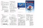
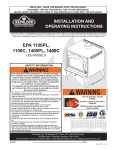
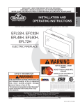
9 3.1 MINIMUM CLEARANCE TO COMBUSTIBLES ! WARNING THIS APPLIANCE MUST REMAIN REMOVABLE FROM THE ENCLOSURE. THE APPLIANCE MAY BE HARD WIRED, BUT IT IS RECOMMENDED THAT IT BE PLUGGED INTO A STANDARD OUTLET USING THE SUPPLIED POWER CORD. THIS APPLIANCE MUST NOT BE SEALED AROUND THE FRONT FACING. APPLIANCE VENTS LOCATED ON THE FRONT AND BACK OF THIS ELECTRIC APPLIANCE CANNOT, IN ANY WAY, BE COVERED AS IT MAY CREATE A FIRE HAZARD. Sides, back, top 3.2 1" MINIMUM MANTEL CLEARANCES ! WARNING RISK OF FIRE, MAINTAIN ALL SPECIFIED AIR SPACE CLEARANCES TO COMBUSTIBLES. FAILURE TO COMPLY WITH THESE INSTRUCTIONS MAY CAUSE A FIRE OR CAUSE THE APPLIANCE TO OVERHEAT. ENSURE ALL CLEARANCES (I.E. BACK, SIDE, TOP, VENT, MANTEL, FRONT, ETC.) ARE CLEARLY MAINTAINED. WHEN USING PAINT OR LACQUER TO FINISH THE MANTEL, THE PAINT OR LACQUER MUST BE HEAT RESISTANT TO PREVENT DISCOLOURATION. 73.1 The minimum distance from the top of the appliance that the mantel can be installed is 10", at any depth. MANTEL WALL 10” FRONT GLASS APPLIANCE SIDEVIEW OPTIONAL HEARTH W415-0675 / D / 12.14.11 10 3.3 3.4 3.5 NEW CONSTRUCTION OR RENOVATION A. Select a location that is not prone to moisture and is located at least 0.9 m or 3 feet away from combustible materials such as curtains or drapes, furniture, bedding, paper, etc. B. Place the appliance in selected location to see how it will look in the future. C. Mark the desired location on the floor and store appliance in a safe, dry and dust free location. D. Frame in an opening leaving at least 1/4" (6 mm) around the edge of the appliance. Any new wiring must be done in compliance with local and national codes and other applicable regulations in order to reduce the risk of fire, electric shock or other injuries. Therefore, it is strongly recommended that you hire a professional to complete any such work. INSTALLING THE APPLIANCE A. Once the site has been prepared, the appliance can be installed. B. Make sure the main power switch is in the "OFF" position. C. Plug the appliance into a 15-amp/120 Volt, grounded outlet. Use a CSA or UL approved surge protector. D. Push in the appliance so that the trim is against the finished mantel or wall surface. THERMOSTAT AND THERMAL SENSOR INSTALLATION This appliance has two options for heat control. First is a thermal controlled sensor, which comes plugged into the appliance beside the main power cord. This sensor has no user temperature set points, it will turn off the heater when the sensor reaches its pre-set point, and will only turn the heater back on when it has cooled back down below this set point. On the low setting (green light) the set point is 16°C/61°F, on medium (orange light) 22°C/72°F and on high (red light) 28°C/82°F. This small sensor can be placed anywhere in the room within the length of the sensor wire, but it should not be placed near the top or front of the appliance. Placing the sensor too close to the heater area of the appliance will cause unwanted cycling of the heater. Second is the option of a wall-mounted thermostat. Napoleon Part # W690-0001, W660-0081, or an equivalent low voltage thermostat. A wall thermostat can be used in place of the thermal control sensor. You must first remove the sensor by unplugging it from the right side of the appliance beside the main power cord. Replace the sensor with the wire harness provided in the manual baggie. Plug it into the appliance and connect the other end to the thermostat. The thermostat should be placed as per the thermostat installation instructions. W415-0675 / D / 12.14.11 11 3.6 HARD-WIRE INSTALLATION ! WARNING ENSURE ALL POWER IS TURNED OFF BEFORE HARD WIRING THIS APPLIANCE. HARD WIRING CONNECTION If it is necessary to hard wire this appliance, a qualified electrician may remove the cord connection, and wire the appliance directly to the house hold wiring. This appliance must be electrically connected and grounded in accordance with local codes, if hard wired. In the absence of local codes, use the current CSA C22.1 CANADIAN ELECTRICAL CODE in Canada or the current ANSI/NFPA 70 NATIONAL ELECTRICAL CODE in the United States. A. Remove cover plate located beside the power cord to reveal the 7/8” wire hole. Discard cover plate, screws and insert a box connector into the hole. B. Remove the lower back panel from the appliance to expose wiring. C. Remove the power cord strain-relief from the side of the appliance and cut the cord where shown below. This will be the hard wire connection point. D. Feed the supply wires through the box connector and the grommet. E. Using wire connectors connect the common (white) wires together, then the hot (black) wires, and then the ground (green) wires. F. Ensure the newly connected wires are kept away from the rotating parts and the circuit board, and reinstall the back panel. NOTE: This appliance must be serviced from the back, leave enough wire so that the appliance can be removed from the enclosure without disconnecting the power supply wires. Power Cord Cut 1 Remove 2 screws on cover plate. 3 Hot Wire Common Wire 2 Ground Wire Box Connector 4 Final Connection W415-0675 / D / 12.14.11 12 4.0 FRAMING ! WARNING RISK OF FIRE! IN ORDER TO AVOID THE POSSIBILITY OF EXPOSED INSULATION OR VAPOUR BARRIER COMING IN CONTACT WITH THE APPLIANCE BODY, IT IS RECOMMENDED THAT THE WALLS OF THE APPLIANCE ENCLOSURE BE “FINISHED” (IE: DRYWALL / SHEETROCK), AS YOU WOULD FINISH ANY OTHER OUTSIDE WALL OF A HOME. THIS WILL ENSURE THAT CLEARANCE TO COMBUSTIBLES IS MAINTAINED WITHIN THE CAVITY. DO NOT NOTCH THE FRAMING AROUND THE APPLIANCE STAND-OFFS. FAILURE TO MAINTAIN AIR SPACE CLEARANCE MAY CAUSE OVER HEATING AND FIRE. PREVENT CONTACT WITH SAGGING OR LOOSE INSULATION OR FRAMING AND OTHER COMBUSTIBLE MATERIALS. BLOCK OPENING INTO THE CHASE TO PREVENT ENTRY OF BLOWN-IN INSULATION. MAKE SURE INSULATION AND OTHER MATERIALS ARE SECURED. WHEN CONSTRUCTING THE ENCLOSURE ALLOW FOR FINISHING MATERIAL THICKNESS TO MAINTAIN CLEARANCES. FRAMING OR FINISHING MATERIAL CLOSER THAN THE MINIMUMS LISTED MUST BE CONSTRUCTED ENTIRELY OF NON-COMBUSTIBLE MATERIALS. MATERIALS CONSISTING ENTIRELY OF STEEL, IRON, BRICK, TILE, CONCRETE, SLATE, GLASS OR PLASTERS, OR ANY COMBINATION THEREOF ARE SUITABLE. MATERIALS THAT ARE REPORTED AS PASSING ASTM E 136, STANDARD TEST METHOD FOR BEHAVIOUR OF MATERIALS IN A VERTICAL TUBE FURNACE AT 750°C AND UL763 SHALL BE CONSIDERED NON-COMBUSTIBLE MATERIALS. MINIMUM CLEARANCE TO COMBUSTIBLES MUST BE MAINTAINED OR A SERIOUS FIRE HAZARD COULD RESULT. THE APPLIANCE REQUIRES A MINIMUM ENCLOSURE HEIGHT. MEASURE FROM THE APPLIANCE BASE. IF STEEL STUD FRAMING KITS WITH CEMENT BOARD ARE PROVIDED, THEY MUST BE INSTALLED. 71.1 H EA DER 31 1/2” 3 ” 11 /4 W415-0675 / D / 12.14.11 29” 13 5.0 FINISHING ! WARNING RISK OF FIRE! NEVER OBSTRUCT THE FRONT OPENING OF THE APPLIANCE. DO NOT STRIKE, SLAM OR SCRATCH GLASS. DO NOT OPERATE APPLIANCE WITH GLASS REMOVED, CRACKED, BROKEN OR SCRATCHED. FACING AND/OR FINISHING MATERIAL MUST NEVER OVERHANG INTO THE APPLIANCE OPENING. 5.1 HEARTH A hearth is NOT necessary but is recommended for aesthetic purposes. 5.2 COLD CLIMATE INSTALLATION ! WARNING IT IS MANDATORY TO HAVE AN INSULATED WALL BEHIND THE APPLIANCE, WHEN THE APPLIANCE IS BEING INSTALLED ON AN OUTSIDE WALL OR CHASE. 5.3 FINISHING CHECKLIST A. Power supply service must be completed prior to finishing to avoid reconstruction. B. Appliance vents and air openings cannot be covered in any circumstances. W415-0675 / D / 12.14.11 14 6.0 OPERATING INSTRUCTIONS The controls are located on the bottom right corner of the appliance. A. Plug in your electric appliance. B. Main ON/OFF Power Switch and LED: This switch is located on the right side of the control panel. The "|" indicates ON and "O" indicates OFF. When the appliance is first turned on, the default settings are as follows: - Ember bed: HIGH - Flame: HIGH - Appliance: OFF C. Temperature Control Button and LED: The Appliance LED is located to the right of the FLAME Button. Push the TEMP button to cycle through different appliance settings. Press and release the TEMP button to cycle through LO, MED,HI and OFF. Each time the TEMP button is pushed, the Appliance LED will change to its corresponding color: Green for LO (approximately 16°C / 61°F) , Orange for MED (approximately 22°C / 72°F), Red for HI (approximately 28°C / 82°F), and blank for OFF. When the appliance is turned on, heat will emit through the vents located in the middle of the top louvre panel. The appliance has a built-in thermostat so it will shut off automatically once the pre-set temperature is reached. It will also turn on automatically if the room temperature drops below the pre-set temperature. NOTE: When the appliance is turned on for the first time, it may release a slight, harmless odour. This odour is a normal occurrence caused by the initial heating of the internal heating elements and should not occur again. D. Flame Control Button: This button is located to the right of the TEMP Button. After power is turned on, push the FLAME control button to adjust the flame and ember bed brightness. Press and release the Flame Control Button to cycle through LO, MED,HI and OFF. CONTROLS FOR ELECTRIC APPLIANCE Temperature Control Button Heater LED TEMP FLAME Heater Remote Control Receiver Power LED Flame Control Button W415-0675 / D / 12.14.11 ON/OFF Power Button 15 6.1 OPERATING BY REMOTE CONTROL Once the appliance has been plugged in to a grounded electrical outlet, it is ready to operate. A. Plug in your electric appliance. B. is at the ON position! The remote control will NOT Make sure the appliance's main power button work if the main Power button is at the OFF position. NOTE: Ensure the house circuit breakers for the power supply are turned on. In the event of a power failure, when the main switch is in the ON position and the hand held remote control is in the OFF position, the flame generation lights will come on at the high setting, however the heater remains turned off when the power is restored. C. When operating the remote control, it must be directed towards the front of the appliance. D. The button at the top left corner of the remote is the main power button . Pressing this button activates the power to the appliance. NOTE: The main power switch on the appliance must be in the ON position for the remote to operate. E. To adjust the ember bed brightness, press the “+” or “-” buttons. To increase the ember bed brightness, press the “+” button, to decrease the ember bed brightness, press the "-" button. There are seven levels of brightness. F. To activate the heater, press the button. Press and release the button to cycle through LO, MED, HI and OFF. Each time the button is pushed, the appliance LED will change to its corresponding color: Green for LO, Orange for MED, Red for HI, and blank for OFF. The appliance has a built-in thermostat so it will shut off automatically once the pre-set temperature is reached. It will also turn on automatically if the room temperature drops below the pre-set temperature. G. To adjust the height of the flame, press the “+” or “-” buttons. To increase the height of the flame, press the “+” button, to decrease the height of the flame, press the "-" button. There are seven levels of flame effects. H. To turn off the appliance, press the button once. NOTICE: This remote control must remain within 8 meters or 26 feet of the appliance to be effective and this range may be reduced as battery power is depleted. REMOTE CONTROL FOR ELECTRIC FIREPLACE Infrared Ray Exit - - + Indicator Light + NOTE: Make sure your batteries are fully charged and installed correctly in your remote control. W415-0675 / D / 12.14.11 16 7.0 MAINTENANCE ! WARNING ALWAYS DISCONNECT THE POWER AND ALLOW THE ELECTRIC APPLIANCE TO COOL BEFORE PERFORMING ANY CLEANING, MAINTENANCE OR RELOCATION OF THIS ELECTRIC APPLIANCE. TURN CONTROLS TO OFF AND REMOVE PLUG FROM OUTLET OR TURN OFF THE HOUSE CIRCUIT BREAKER TO ELECTRIC APPLIANCE RECEPTACLE. DO NOT INSTALL REPLACEMENT BULBS THAT EXCEED SPECIFIED MAXIMUM WATTS. THE HALOGEN LIGHT BULBS IN YOUR UNIT CAN BECOME EXTREMELY HOT. ALLOW AT LEAST 10 MINUTES BETWEEN TURNING OFF THE APPLIANCE AND REMOVING THE LIGHT BULBS TO AVOID ACCIDENTAL BURNS. DO NOT HANDLE THE LAMP (BULBS) WITH BARE FINGERS, OILS FROM YOUR SKIN WILL DAMAGE THE BULBS WHEY THEY HEAT UP. USE GLOVES OR A CLEAN DRY CLOTH WHEN HANDLING BULBS. Most halogen lamps are rated to last approximately 1800 hours. Like all lamps, halogen lamps require periodic replacement. When the lamps in your appliance have burned out, you will notice one or more of following: COMMON OBSERVED PROBLEMS: - There is no flame - Flame or Ember bed is dim or dark in certain areas - Flame is not moving or glowing Your appliance must be opened in order to replace the lamp. To reduce the number of times you need to open the appliance, replace all lamps at the same time if they are close to the end of their rated life. LAMP TYPE: G 6.35, 120V, 35W Maximum There are a total of 8 halogen lamps (Type G6.35, rated 120Volts, 35Watts) supplied with your appliance: - 2 lamps provide illumination for the ember bed - 2 lamps provide illumination for flame generation - 4 extra lamps for replacement 8 pcs included W415-0675 / D / 12.14.11 17 7.1 FLAME GENERATION LAMP REPLACEMENT A. B. Remove the 7 screws from the bottom half of the back of appliance illustrated. Remove back plate. BACK PLATE Locate the flame generation cylinder drum. It is constructed of two removable halves. They are two (2) matte black sheet metal pieces with holes in them, either of which can be removed from the appliance. Back View of Appliance C. Remove the screw as illustrated, that is used to secure the flame generation cylinder drum. D. Squeeze half of drum cylinder until its top edge clears the top drum track. Remove the bottom edge of the cylinder drum from the bottom drum track. This will give you access to the lamps. NOTE: Do not exert excessive pressures on the drum cylinder as this may cause damage. E. Remove spring clip. Hold socket and pull out old lamp. F. Hold socket and push in new lamp (DO NOT exceed wattage). Replace spring clip. G. Repeat steps C and D for the second lamp. H. Insert bottom edge of removed cylinder half into bottom drum track. Gently squeeze drum cylinder until its top edge fit into top drum rack. Reattach the screw that was removed in step B. I. Secure the back plate of the appliance to the main appliance by reattaching the 7 screws removed from step A. 2 Screws On The Side 3 Screws On The Back Mantel 2 Screws On The Side FLAME GENERATION CYLINDER DRUM Flame Generation Cylinder Drum Screw FLAME GENERATION CYLINDER DRUM Flame Generation Cylinder Drum Squeeze DRUM LAMP REPLACEMENT Bulbs with Spring Flame Generation Clips Cylinder Drum W415-0675 / D / 12.14.11 18 7.2 EMBER BED LAMP REPLACEMENT A. Remove the 7 screws from the bottom half of the back of appliance as illustrated. Remove back plate. B. Locate the ember bed lamps which are underneath the flame generation cylinder drum. C. Remove spring clip. Hold socket and pull out old lamp. D. Hold socket and push in new lamp (DO NOT exceed wattage or handle with bare hands). E. Repeat steps C and D for the second lamp. F. Secure the back plate of the appliance to the main appliance by reattaching the 7 screws removed from step A. BACK PLATE Mantel Back View of Appliance 2 Screws On The Side 2 Screws On The Side 3 Screws On The Back LOCATE THE EMBER BED LAMPS Flame Generation Cylinder Drum Bulbs with Spring Clips EMBER BED LAMP REPLACEMENT 7.3 CARE OF GLASS DO NOT CLEAN GLASS WHEN HOT! DO NOT USE ABRASIVE CLEANERS TO CLEAN GLASS. ! WARNING HOT GLASS WILL CAUSE BURNS. Buff lightly with a clean dry soft cloth. Clean both sides of the glass after the first 10 hours of operation with a recommended fireplace glass cleaner. Thereafter clean as required. If the glass is not kept clean permanent discoloration and / or blemishes may result. DO NOT TOUCH GLASS UNTIL COOLED. NEVER ALLOW CHILDREN TO TOUCH GLASS. 5.1 W415-0675 / D / 12.14.11 N SW-SPST MICROSWITCH SW-SPST N P-SW 6.3*0.8 P-NI F2 FUSE2 L1 INDUCTOR IRON L1 IR R6 10K t t130 F2 +5V PTC TEMP_BRK INDUCTOR IRON 6.3*0.8 PH-7 C10 X2,1U/250V S1 3 2 1 R14 10K 1K 2K R8 R12 TRANS1 6.3*0.8 P-NO 4 RED R18 1K GREEN R7 1K SW-PB SW-PB K-S2 2.4*2 K-S1 1 2 TEMP 1N4148 D9 D-LED0 8050 R15 10K C1 GREEN D-LED0 R19 1K 1K R17 10K 2.4*7 1 2 3 4 5 6 SIP2 1OOOU/25V 1N4007 D8 R9 10K R14 2 1N4007 *4 LED1 C8 104 R13 1.5K T4 6.3*0.8 6.3*0.58 230V,120V/12V P-L PH-6 1 3 MICROSWITCH 8050 T5 10K C7 104 C6 20P C5 20P R15 R16 10K C2 104 4M 1 16 15 3 2 19 P5.3 P5.2 11 P0.4 P4.2/AIN2 P4.1/AIN1 XOUT XIN P0.0 Vout 7805 12 C9 104 5 X Vin IC1 3 20 SN8P2722 1000U/16V C3 VDD C4 104 +5 VSS 10 P5.1 P5.0 P0.7 P0.5 P0.6 510 10 R5 510 9 R4 510 8 R2 6 7 R3 510 R1 510 T3 8050 8050 T2 T1 8050 1N4007 1N4007 1N4007 4022 IC4 3022 IC3 D7 D6 D5 6.3*0.8 MOTOR H2 6.3*0.8 FIRE 6.3*0.8 LAMP BTA16 TR.2 FAN MOTOR H1 BTA16 MOTOR RELAY-MOTOR 6.3*0.8 H2 PH-2 RELAY-H2 6.3*0.8 H1+FAN PH-1 RELAY-H1 5.1K R11 5.1K R10 TR.1 PH-4 6.3*0.8 LAMP A? LAMP A? ! R20 470K 8.0 WIRING DIAGRAM 25*C,5K THERMISTOR GND 2 L1 19 ENSURE ALL POWER IS TURNED OFF BEFORE HARD WIRING THIS APPLIANCE. WARNING W415-0675 / D / 12.14.11 20 9.0 REPLACEMENT PARTS Contact your dealer or the factory for questions concerning prices and policies on replacement parts. Normally all parts can be ordered through your Authorized dealer / distributor. FOR WARRANTY REPLACEMENT PARTS, A PHOTOCOPY OF THE ORIGINAL INVOICE WILL BE REQUIRED TO HONOUR THE CLAIM. When ordering replacement parts always give the following information: • Model & Serial Number of appliance • Installation date of appliance • Part number • Description of part • Finish * IDENTIFIES ITEMS WHICH ARE NOT ILLUSTRATED. FOR FURTHER INFORMATION, CONTACT YOUR AUTHORIZED DEALER. ! WARNING FAILURE TO POSITION THE PARTS IN ACCORDANCE WITH THIS MANUAL OR FAILURE TO USE ONLY PARTS SPECIFICALLY APPROVED WITH THIS APPLIANCE MAY RESULT IN PROPERTY DAMAGE OR PERSONAL INJURY. 41.1 For aftermarket sales and service please call 1-866-592-6667 COMPONENTS REF # PART # DESCRIPTION 1 DQ017-002 LAMPS 2 RC3 DQ002-006 CIRCUIT BOARD 3 Q/T FRT01-000-00B HEATER (HEATER WITH BLOWER) 4 DQ006-003 SWITCH 5 R-19 REMOTE CONTROL ACCESSORIES REF # PART # DESCRIPTION 6* W660-0081 DIGITAL THERMOSTAT 7* W690-0001 MILLIVOLT THERMOSTAT NOTE: Care must be taken when removing and disposing of any broken glass or damaged components. Be sure to vacuum up any broken glass from inside the appliance before operation. 3 1 2 4 ON/OFF - + 5 - W415-0675 / D / 12.14.11 + 21 10.0 TROUBLE SHOOTING ! WARNING TURN OFF THE APPLIANCE COMPLETELY AND LET COOL BEFORE SERVICING. ONLY A QUALIFIED SERVICE PERSON SHOULD SERVICE AND REPAIR THIS ELECTRIC APPLIANCE. SYMPTOM PROBLEM TEST SOLUTION Dim or no flame Bulb(s) are burnt out Inspect the bulbs inside the flame generation cylinder drum and replace them if necessary Ember bed is not glowing or dimming Bulb(s) are burnt out Inspect the ember bed bulbs and replace them if necessary No warm air coming out of appliance Room temperature is higher than the appliance setting (if it is set to LO or MED) Set appliance to a higher temperature setting (MED or HI) Appliance turns off and will not turn on Appliance has overheated and safety device has caused the thermal switch to disconnect Unplug the appliance, allow appliance to cool for 15 minutes, then plug it back in House circuit breaker has tripped Reset house circuit breaker Appliance will not come on when switch is flipped to ON Appliance is not plugged into an electrical outlet Check plug and plug it in Appliance has overheated and safety device has caused the thermal switch to disconnect Unplug the appliance, allow appliance to cool for 15 minutes, then plug it back in Remote control does not work Low batteries Replace batteries in remote control Heater shuts off automatically Room is too warm The heater has a built-in thermostat so it will shut off automatically once the pre-set temperature is reached. It will also turn on automatically if the room temperature drops below the pre-set temperature 42.23 W415-0675 / D / 12.14.11 22 11.0 WARRANTY NAPOLEON® electric appliances are manufactured under the strict Standard of the world recognized ISO 9001 : 2008 Quality Assurance Certificate. NAPOLEON® products are designed with superior components and materials, assembled by trained craftsmen who take great pride in their work. Once assembled the complete appliance is thoroughly inspected by a qualified technician before packing to ensure that you , the customer, receive the quality product that you expect from NAPOLEON®. NAPOLEON® ELECTRIC APPLIANCE LIMITED WARRANTY Electrical components and wearable parts such as fan/heater, motors, switches, nylon bearing components and remote controls are covered and NAPOLEON® will provide replacement parts free of charge during the first year of limited warranty. Light bulbs and fuses are NOT covered by the warranty. Any labour related to warranty repair is not covered. * Construction of models vary. Warranty applies only to components included with your specific appliance. CONDITIONS AND LIMITATIONS NAPOLEON® warrants its products against manufacturing defects to the original purchaser only. Registering your warranty is not necessary. Simply provide your proof of purchase along with the model and serial number to make a warranty claim. NAPOLEON® reserves the right to have its representative inspect any product or part thereof prior to honouring any warranty claim. Provided that the purchase was made through an authorized NAPOLEON® dealer your appliance is subject to the following conditions and limitations: Warranty coverage begins on the date of original installation. This factory warranty is non-transferable and may not be extended whatsoever by any of our representatives. Installation must be done in accordance with the installation instructions included with the product and all local and national building and fire codes. This limited warranty does not cover damages caused by misuse, lack of maintenance, accident, alterations, abuse or neglect and parts installed from other manufacturers will nullify this warranty. This limited warranty further does not cover any scratches, dents, corrosion or discoloring caused by excessive heat, abrasive and chemical cleaners nor chipping on porcelain enamel parts, mechanical breakage of PHAZER™ logs. In the first year only, this warranty extends to the repair or replacement of warranted parts which are defective in material or workmanship provided that the product has been operated in accordance with the operation instructions and under normal conditions. NAPOLEON® will not be responsible for installation, labour or any other expenses related to the reinstallation of a warranted part and such expenses are not covered by this warranty. Notwithstanding any provisions contained in the Limited Warranty, NAPOLEON’s responsibility under this warranty is defined as above and it shall not in any event extend to any incidental, consequential or indirect damages. This warranty defines the obligations and liability of NAPOLEON® with respect to the NAPOLEON® electric appliance and any other warranties expressed or implied with respect to this product, its components or accessories are excluded. NAPOLEON® neither assumes, nor authorizes any third party to assume, on its behalf, any other liabilities with respect to the sale of this product. Any damages to appliance, brass trim or other component due to water, weather damage, long periods of dampness, condensation, damaging chemicals or cleaners will not be the responsibility of NAPOLEON®. The bill of sale or copy will be required together with a serial number and a model number when making any warranty claims from your authorized dealer. The warranty registration card must be returned within fourteen days to register the warranty. NAPOLEON® reserves the right to have its representative inspect any product or part thereof prior to honouring any warranty claim. All parts replaced under the Limited Warranty Policy are subject to a single claim. All parts replaced under the warranty will be covered for a period of 90 days from the date of their installation. The manufacturer may require that defective parts or products be returned or that digital pictures be provided to support the claim. Returned products are to be shipped prepaid to the manufacturer for investigation. If a product is found to be defective, the manufacturer will repair or replace such defect. Before shipping your appliance or defective components, your dealer must obtain an authorization number. Any merchandise shipped without authorization will be refused and returned to sender. Shipping costs are not covered under this warranty. Additional service fees may apply if you are seeking warranty service from a dealer. ALL SPECIFICATIONS AND DESIGNS ARE SUBJECT TO CHANGE WITHOUT PRIOR NOTICE DUE TO ON-GOING PRODUCT IMPROVEMENTS. NAPOLEON® IS A REGISTERED TRADEMARK OF WOLF STEEL LTD. 2.5B W415-0675 / D / 12.14.11 23 12.0 SERVICE HISTORY 43.1 W415-0675 / D / 12.14.11 24 12.0 NOTES 44.1 W415-0675 / D / 12.14.11 24 11.0 NOTES 44.1 W415-0675 / C / 12.19.11 Date Détaillant Historique d’entretien Wolf Steel Problèmes particuliers 12.0 Travail effectué Cet appareil doit être entretenu annuellement selon son usage. Nom du technicien W415-0675 / C / 12.19.11 43.1 HISTORIQUE D’ENTRETIEN 23 22 11.0 GARANTIE Les foyers électriques NAPOLÉON® sont fabriqués conformément aux normes strictes du Certicat d’Assurance de Qualité mondialement reconnu ISO 9001 : 2008. Les produits NAPOLÉON® sont conçus avec des composants et des matériaux de qualité supérieure, assemblés par des artisans qualiés qui sont ers de leur travail. Une fois assemblé, chaque foyer est soigneusement inspecté par un technicien qualié avant d’être emballé pour garantir que vous, le client, recevez le produit de qualité dont vous vous attendez de NAPOLÉON®. GARANTIE LIMITÉE DES APPAREILS ÉLECTRIQUES NAPOLÉON® Les composants électriques et les pièces soumises à l’usure tels que la souferie/chaufferette, les moteurs, les interrupteurs, les roulements à billes en nylon et les télécommandes sont couverts et NAPOLÉON® fournira gratuitement les pièces de rechange durant la première année de la garantie limitée. Les ampoules et les fusibles NE SONT PAS couverts par la garantie. Les coûts de main-d’oeuvre relatifs aux réparations garanties ne sont pas couverts. *La fabrication de chaque modèle varie. La garantie s’applique uniquement aux composants disponibles avec votre appareil. CONDITIONS ET LIMITATIONS NAPOLÉON® garantit ses produits contre les défauts de fabrication à l’acheteur d’origine seulement. L’enregistrement de la garantie n’est pas nécessaire. Fournissez simplement une preuve d’achat ainsi que le modèle et le numéro de série an d’effectuer une réclamation de garantie. Napoléon® se réserve le droit de demander à son représentant d’inspecter tous produits ou pièces avant d’honorer toute réclamation. L’achat doit avoir été fait par l’entremise d’un détaillant NAPOLÉON® autorisé et sous réserve des conditions et limitations suivantes : La couverture de la garantie débute à partir de la date d’installation originale. Cette garantie du fabricant n’est pas transférable et ne peut être prolongée ou étendue par aucun de nos représentants quelle qu’en soit la raison. L’installation doit être faite conformément aux instructions d’installation incluses avec le produit et à tous les codes d’incendie et de construction locaux et nationaux. Cette garantie limitée ne couvre pas les dommages causés par un mauvais usage, un manque d’entretien, un accident, des altérations, des abus ou de la négligence, et l’installation de pièces d’autres fabricants annulera cette garantie. Cette garantie limitée ne couvre pas non plus les égratignures, les bossellements, la corrosion ou la décoloration causée par une chaleur excessive, des produits d’entretien chimiques et abrasifs ou l’écaillage de pièces en porcelaine émaillée, le bris par manipulation des bûches Phazer®. Au cours de la première année seulement, cette garantie s’étend à la réparation ou au remplacement des pièces garanties dont les matériaux ou la fabrication sont défectueux à la condition que le produit ait été utilisé conformément aux instructions de fonctionnement et dans des conditions normales. NAPOLÉON® ne sera pas responsable de l’installation, de la main-d’oeuvre ou autres coûts ou dépenses relatives à la réinstallation d’une pièce garantie, et de telles dépenses ne sont pas couvertes par cette garantie. Nonobstant toutes les dispositions contenues dans cette Garantie Limitée, la responsabilité de NAPOLÉON® sous cette garantie est dénie comme ci-dessus et elle ne s’étendra à aucun dommage accidentel, consécutif ou indirect. Cette garantie dénit l’obligation et la responsabilité de NAPOLÉON® en ce qui concerne l’appareil électrique NAPOLÉON®. Toute autre garantie énoncée ou implicite en ce qui concerne ce produit, ses composants ou accessoires est exclue. NAPOLÉON® n’endosse, ni n’autorise aucun tiers à assumer en son nom, toutes autres responsabilités concernant la vente de ce produit. Tous dommages causés à l’appareil, aux garnitures en laiton ou autres composants par l’eau, les dommages causés par les intempéries, de longues périodes d’humidité, la condensation, des produits chimiques ou produits d’entretien nuisibles ne seront pas la responsabilité de NAPOLÉON®. La facture ou sa copie sera requise ainsi que le numéro de série et le numéro de modèle lors d’une réclamation auprès de votre détaillant autorisé. La carte d’enregistrement de garantie doit être retournée dans les quatorze jours pour enregistrer la garantie. NAPOLÉON® se réserve le droit de demander à son représentant d’inspecter tout produit ou pièce avant d’honorer toute réclamation. Toutes les pièces remplacées en vertu de la politique de Garantie limitée ne peuvent faire l’objet que d’une seule réclamation. Toutes les pièces remplacées au titre de la garantie seront couvertes pour une période de 90 jours à partir de leur date d’installation. Le fabricant peut exiger que les pièces défectueuses ou les produits soient retournés ou que des photos numériques soient fournies pour valider la réclamation. Les produits retournés doivent être expédiés port payé au fabricant pour une inspection en usine. Si un produit est déclaré défectueux, le fabricant le réparera ou le remplacera. Avant d’expédier votre appareil ou les pièces défectueuses, votre détaillant doit obtenir un numéro d’autorisation. Toute marchandise expédiée à notre usine sans autorisation sera refusée et retournée à l’expéditeur. Les coûts d’expédition ne sont pas couverts par cette garantie. Des frais de service supplémentaires peuvent être appliqués si vous cherchez à obtenir des services au titre de la garantie auprès d’un détaillant. TOUTES LES SPÉCIFICATIONS ET LES CONCEPTIONS SONT SUJETTES À MODIFICATIONS SANS PRÉAVIS EN RAISON DES AMÉLIORATIONS CONSTANTES APPORTÉES AUX PRODUITS. NAPOLÉON® EST UNE MARQUE DE COMMERCE DÉPOSÉE DE WOLF STEEL LTÉE. 2.5B W415-0675 / C / 12.19.11 10.0 21 GUIDE DE DÉPANNAGE ! AVERTISSEMENT COUPEZ L’ALIMENTATION ÉLECTRIQUE À L’APPAREIL ET LAISSEZ-LE REFROIDIR AVANT D’EFFECTUER UN ENTRETIEN. SEUL UN TECHNICIEN DE SERVICE QUALIFIÉ PEUT EFFECTUER L’ENTRETIEN OU LA RÉPARATION DE CET APPAREIL. SYMPTÔME PROBLÈME SOLUTIONS La température ambiante est trop élevée. La chaufferette s'éteint automatiquement. Remplacez les piles AA de la télécommande. Les piles sont faibles. La télécommande ne fonctionne pas. Débranchez l'appareil, laissez-le refroidir pendant 10 minutes, puis rebranchez-le. L'appareil a surchauffé et le dispositif de sécurité a entraîné le déclenchement de l'interrupteur thermique. Vériez la che puis rebranchez-la. L'appareil n'est pas branché dans une prise de courant. Réinitialisez le disjoncteur. Le disjoncteur de la maison s'est déclenché. Débranchez l'appareil, laissez-le refroidir pendant 10 minutes, puis rebranchez-le. L'appareil a surchauffé et le dispositif de sécurité a entraîné le déclenchement de l'interrupteur thermique. L’appareil s’éteint et ne se rallume pas. Réglez l’appareil à une température plus élevée (MOYEN ou ÉLEVÉ). La température ambiante est plus élevée que le réglage de l’appareil (si réglée à BAS ou MOYEN). L’appareil n’émet aucune chaleur. La/les ampoule(s) sont brûlées. Le lit de braises ne s’illumine pas ou ne diminue pas en luminosité. La/les ampoule(s) sont brûlées. La luminosité du jeu de ammes est faible ou inexistante. L'appareil ne s'allume pas lorsque l'interrupteur est mis à « ON ». Vériez les ampoules à l’intérieur du cylindre de création du jeu de ammes et remplacez-les au besoin. Vériez les ampoules du lit de braises et remplacez-les au besoin. L'appareil est équipé d’un thermostat intégré et s’éteindra automatiquement lorsque la température programmée sera atteinte. Il s’allumera automatiquement lorsque la température de la pièce descendra en dessous de la température programmée. La température programmée dépend des réglages sélectionnés pour la chaufferette. 42.23 W415-0675 / C / 12.19.11 20 9.0 RECHANGES Contactez votre détaillant ou le fabricant pour les questions concernant les prix et la disponibilité des pièces de rechange. Normalement, toutes les pièces peuvent être commandées chez votre détaillant autorisé. POUR UN REMPLACEMENT DE PIÈCE SOUS GARANTIE, UNE PHOTOCOPIE DE LA FACTURE ORIGINALE SERA REQUISE AFIN DE POUVOIR HONORER LA DEMANDE. Lorsque vous commandez des pièces, donnez toujours l’information suivante : Modèle et numéro de série de l’appareil Date d’installation de l’appareil Numéro de la pièce OMETTRE DE POSITIONNER LES PIÈCES Description de la pièce CONFORMÉMENT AU MANUEL OU D’UTILISER Fini UNIQUEMENT DES PIÈCES SPÉCIFIQUEMENT * IDENTIFIE LES ARTICLES QUI NE SONT PAS APPROUVÉES POUR CET APPAREIL PEUT ILLUSTRÉS. POUR PLUS D’INFORMATION, CAUSER DES DOMMAGES MATÉRIELS CONTACTEZ VOTRE DÉTAILLANT AUTORISÉ. OU DES BLESSURES CORPORELLES. ! AVERTISSEMENT 41.1 Pour le service après-vente, veuillez composer le 1-866-592-6667 COMPOSANTS THERMOSTAT MILLIVOLT W690-0001 7* THERMOSTAT NUMÉRIQUE W660-0081 6* N° DE PIÈCE N° RÉF. TÉLÉCOMMANDE R-19 5 INTERRUPTEURS DQ006-003 4 CHAUFFERETTE (CHAUFFERETTE AVEC SOUFFLERIE) Q/T FRT01-000-00B 3 CARTE DE CIRCUITS IMPRIMÉS RC3 DQ002-006 2 AMPOULES DQ017-002 1 N° DE PIÈCE N° RÉF. DESCRIPTION ACCESSOIRES DESCRIPTION NOTE : Usez de prudence lorsque vous enlevez et jetez des débris de verre ou des composants endommagés. Assurez-vous d’aspirer tous les débris de verre à l’intérieur de l'appareil avant de le faire fonctionner. 3 1 2 4 ON/OFF - - + 5 + W415-0675 / C / 12.19.11 L1 N MICROCONTACT S1 PH-7 PTC DISJONCTEUR THERMIQUE F2 PH-6 6.3*0.8 P-L 8050 T4 6.3*0.58 4 C8 104 R13 1.5K 230V,120V/12V TRANS1 R14 10K R12 2K R8 1K DEL1 VERT 1 R7 1K D8 C1 2.4*7 1 2 3 4 5 6 SIP2 1OOOU/25V 1N4007 R17 10K VERT D-LED0 R19 1K 1K R9 10K R14 2 1N4007 *4 D9 1N4148 R18 1K ROUGE D-LED0 SW-PB SW-PB K-S2 2.4*2 K-S1 1 2 TEMP R15 10K 3 FUSIBLE2 L1 t130 3 2 1 P-NO 6.3*0.8 T5 8050 C2 104 R16 10K C7 104 C6 20P C5 20P R15 10K 1 4M X CI1 Vin 19 2 3 15 16 C9 104 5 12 11 MISE À LA TERRE Vout 7805 P5.2 P5.3 P0.4 P4.2/AIN2 P4.1/AIN1 XOUT XIN P0.0 2 F2 t IR R6 10K +5V BOBINE D'INDUCTION - FER L1 C10 X2,1U/250V BOBINE D'INDUCTION - FER 25*C,5K THERMISTOR 6.3*0.8 6.3*0.8 P-NI INTERINTERRUPTEUR RUPTEUR UNIPOLAIRE UNIDIRECTIONNEL MICROCONTACT INTERRUPTEUR N UNIPOLAIRE UNIDIRECTIONNEL R20 470K 3 C3 1000U/16V 20 SN8P2722 +5 C4 104 VDD 10 VSS P0.5 P0.6 8 R2 6 7 510 10 R5 510 9 R4 510 P0.7 P5.0 P5.1 R3 510 R1 510 T1 8050 T2 8050 T3 8050 CI3 3022 CI4 4022 1N4007 1N4007 1N4007 D5 D6 D7 R10 5.1K R11 5.1K TR.1 RELAIS-H1 H1 BTA16 H2 A? LAMPE D'ÉCLAIRAGE ALLUMAGE 6.3*0.8 TR.2 BTA16 PH-4 6.3*0.8 LAMPE D'ÉCLAIRAGE LAMPE D'ÉCLAIRAGE A? 6.3*0.8 MOTEUR DE SOUFFLERIE H1+SOUFFLERIE PH-1 6.3*0.8 H2 PH-2 RELAIS-H2 6.3*0.8 MOTEUR MOTEUR RELAIS-MOTEUR 6.3*0.8 W415-0675 / C / 12.19.11 8.0 SCHÉMA DE CÂBLAGE 19 18 7.2 REMPLACEMENT DES AMPOULES DU LIT DE BRAISES Fixez la plaque arrière à l'appareil en réinstallant les sept vis retirées à l'étape A. F. Répétez les étapes C et D pour la deuxième ampoule. E. Tenez la douille de la nouvelle ampoule et insérez-la (NE PAS excéder la puissance (watts) spéciée ni laisser l'ampoule entrer en contact direct avec vos doigts). D. Retirez l'attache à ressort. Tenez la douille et retirez l'ancienne ampoule. C. Localisez les ampoules du lit de braises qui sont situées en dessous du cylindre de création du jeu de ammes. B. Retirez les sept vis de la moitié inférieure de l'arrière de l'appareil tel qu'illustré. Retirez la plaque arrière. A. PLAQUE ARRIÈRE Tablette Vue arrière de l’appareil 2 vis sur le côté 2 vis sur le côté 3 vis à l’arrière LOCALISATION DES AMPOULES DU LIT DE BRAISES Cylindre de création du jeu de flammes Ampoules avec attaches à ressort REMPLACEMENT DES AMPOULES DU LIT DE BRAISES 7.3 SOINS DE LA VITRE NE PAS NETTOYER LA VITRE LORSQU’ELLE EST CHAUDE! N’EMPLOYEZ PAS DE DÉTERGENTS ABRASIFS POUR NETTOYER LA VITRE. Polissez légèrement à l’aide d’un linge propre et sec. Nettoyez les deux côtés de la vitre avec un nettoyeur recommandé après les dix premières heures de fonctionnement. Par la suite, nettoyez aussi souvent qu’il le faudra, sinon la vitre risque de rester marquée en permanence. ! AVERTISSEMENT LA VITRE CHAUDE CAUSERA DES BRÛLURES. NE PAS TOUCHER LA VITRE AVANT QU’ELLE AIT REFROIDI. NE JAMAIS LAISSER LES ENFANTS TOUCHER LA VITRE. 5.1 W415-0675 / C / 12.19.11 7.1 17 REMPLACEMENT DES AMPOULES DU JEU DE FLAMMES Fixez la plaque arrière à l'appareil en réinstallant les sept vis retirées à l'étape A. I. Insérez la bordure inférieure de la moitié de cylindre retirée auparavant dans le rail inférieur du cylindre. Serrez doucement le cylindre jusqu'à ce que la bordure supérieure soit placée dans le rail supérieur. Réinstallez la vis retirée à l'étape B. H. Répétez les étapes C et D pour la deuxième ampoule. G. Tenez la douille de la nouvelle ampoule et insérezla (NE PAS excéder la puissance (watts) spéciée). Replacez l'attache à ressort. F. Retirez l'attache à ressort. Tenez la douille et retirez l'ancienne ampoule. E. Serrez une moitié du cylindre jusqu’à ce que la bordure supérieure soit libérée du rail supérieur du cylindre. Retirez la bordure inférieure du cylindre du rail inférieur. Vous avez maintenant accès aux ampoules. NOTE : Ne serrez pas trop le cylindre pour ne pas l'endommager. D. Retirez la vis servant à xer le cylindre de création du jeu de ammes, tel qu'illustré. C. Localisez le cylindre de création du jeu de ammes. Il est fabriqué de deux moitiés amovibles. Ce sont deux (2) pièces de tôle noir mat avec des trous qui peuvent être retirées de l'appareil. B. Retirez les sept vis de la moitié inférieure de l'arrière de l'appareil tel qu'illustré. Retirez la plaque arrière. A. PLAQUE ARRIÈRE Tablette Vue arrière de l’appareil 2 vis sur le côté 2 vis sur le côté 3 vis à l’arrière CYLINDRE DE CRÉATION DU JEU DE FLAMMES Cylindre de création du jeu de flammes Vis CYLINDRE DE CRÉATION DU JEU DE FLAMMES Cylindre de création du jeu de flammes Serrez REMPLACEMENT DES AMPOULES Ampoules avec attaches à ressort Cylindre de création du jeu de flammes W415-0675 / C / 12.19.11 16 7.0 ENTRETIEN ! AVERTISSEMENT DÉBRANCHEZ TOUJOURS L'ALIMENTATION ÉLECTRIQUE ET LAISSEZ L’APPAREIL REFROIDIR AVANT D'EFFECTUER UN NETTOYAGE, UN ENTRETIEN OU UNE RELOCALISATION. TOURNEZ LES CONTRÔLES À « OFF » ET RETIREZ LA FICHE DE LA PRISE DE COURANT OU FERMEZ LE DISJONCTEUR DU CIRCUIT DE VOTRE APPAREIL. NE PAS INSTALLER D'AMPOULES DE RECHANGE QUI EXCÈDENT LA PUISSANCE (WATTS) MAXIMALE SPÉCIFIÉE. LES AMPOULES HALOGÈNES DE VOTRE APPAREIL DEVIENNENT TRÈS CHAUDES LORS DE LEUR UTILISATION. POUR ÉVITER DES BRÛLURES ACCIDENTELLES, ATTENDEZ AU MOINS 10 MINUTES APRÈS AVOIR ÉTEINT VOTRE APPAREIL POUR REMPLACER LES AMPOULES. NE MANIPULEZ PAS LES AMPOULES À MAINS NUES, CAR LE GRAS SUR VOS DOIGTS LES ENDOMMAGERA LORSQU'ELLES CHAUFFERONT. UTILISEZ DES GANTS OU UN LINGE PROPRE ET SEC LORSQUE VOUS MANIPULEZ LES AMPOULES. La plupart des ampoules halogènes durent approximativement 1 800 heures. Comme toutes les ampoules, les ampoules halogènes doivent être remplacées périodiquement. Lorsque les ampoules seront brûlées vous constaterez les effets suivants : PROBLÈMES COURANTS : - Il n'y a pas de amme. - La luminosité des ammes ou des braises est faible ou inexistante à certains endroits. - La amme ne bouge pas ou n'illumine pas. TYPE D’AMPOULE : G6.35, 120 V, 35 W Maximum Vous devez ouvrir votre appareil pour remplacer les ampoules brûlées. An d’éviter d'ouvrir votre appareil à plusieurs reprises, nous vous conseillons de remplacer toutes les ampoules en même temps si elles approchent de la n de leur durée de vie. Huit ampoules halogènes (type G6.35, 120 volts, 35 watts) sont fournies avec votre appareil : - 2 ampoules pour la luminosité du lit de braises - 2 ampoules pour la luminosité du jeu de ammes - 4 ampoules de rechange 8 ampoules incluses W415-0675 / C / 12.19.11 6.1 15 UTILISATION DE LA TÉLÉCOMMANDE L'appareil est prêt à fonctionner dès qu'il est correctement branché dans une prise de courant mise à la terre. Pour éteindre l'appareil, appuyez une fois sur la touche « ON/OFF ». NOTE : Pour fonctionner, la télécommande doit être à moins de 8 mètres ou 26 pieds de l'appareil et le rayon devra être diminué au fur et à mesure que la charge de la pile diminuera. H. Pour régler la hauteur des ammes, appuyez sur les touches « + » ou « - ». Pour augmenter la hauteur des ammes, appuyez sur la touche « + », pour diminuer la hauteur des ammes, appuyez sur la touche « - ». Il y a sept réglages différents pour les ammes. G. Pour actionner la chaufferette, appuyez sur la touche . Appuyez et relâchez la touche pour accéder aux différents réglages BAS, MOYEN, ÉLEVÉ et ARRÊT. Chaque fois que la touche est actionnée, le voyant DEL de l'appareil changera de couleur de la façon suivante : vert pour BAS, orange pour MOYEN, rouge pour ÉLEVÉ et éteint pour ARRÊT. L'appareil est équipé d’un thermostat intégré et s’éteindra lorsque la température programmée sera atteinte. Il s’allumera également lorsque la température de la pièce descendra en dessous de la température programmée. F. Pour régler la luminosité du lit de braises, appuyez sur les touches « + » ou « - ». Pour augmenter la luminosité du lit de braises, appuyez sur la touche « + », pour diminuer la luminosité du lit de braises, appuyez sur la touche « - ». Il y a sept réglages différents pour la luminosité. E. La touche située dans le coin supérieur gauche de la télécommande est l'interrupteur . En appuyant sur cette touche, l’appareil est mis sous tension. NOTE : Pour que la télécommande fonctionne, l’interrupteur de l’appareil doit être à « ON ». D. Pointez la télécommande en direction du devant de l'appareil. C. Assurez-vous que l'interrupteur MARCHE/ARRÊT de l’appareil est à « ON ». La télécommande ne peut fonctionner si l'interrupteur MARCHE/ARRÊT est à « OFF ». NOTE : Assurez-vous que les disjoncteurs de la maison pour ce circuit sont allumés. Lors d'une panne de courant, si l’interrupteur est à « ON » et la télécommande manuelle est à « OFF », le système d’éclairage du jeu de flammes se rallumera au réglage élevé quand le courant sera rétabli. Par contre, la chaufferette restera éteinte. B. Branchez votre appareil électrique. A. TÉLÉCOMMANDE POUR APPAREIL ÉLECTRIQUE Rayon infrarouge ON/OFF - Voyant lumineux + - + NOTE : Assurez-vous que les piles de la télécommande sont pleinement chargées et insérées correctement. W415-0675 / C / 12.19.11 14 6.0 INSTRUCTIONS DE FONCTIONNEMENT Les boutons de contrôle sont situés dans le coin inférieur droit de l'appareil. Bouton de contrôle de la température et voyant DEL : C. Interrupteur MARCHE/ARRÊT et voyant DEL : Cet interrupteur est situé du côté droit du panneau de contrôle. Le symbole « | » indique MARCHE et le symbole « O » indique ARRÊT. Lorsque l'appareil est allumé pour la première fois, les réglages par défaut sont les suivants : - Lit de braises : luminosité maximale - Flammes : hauteur maximale - Appareil : arrêt B. Branchez votre appareil électrique. A. Le voyant DEL de l'appareil est situé à la droite du bouton « FLAME ». Appuyez sur le bouton « TEMP » pour voir les différents réglages de l'appareil. Appuyez et relâchez le bouton « TEMP » pour accéder aux réglages BAS, MOYEN, ÉLEVÉ et ARRÊT. Chaque fois que le bouton « TEMP » est actionné, le voyant DEL de l'appareil changera de couleur de la façon suivante : vert pour BAS (environ 16 °C / 61 °F), orange pour MOYEN (environ 22 °C / 72 °F), rouge pour ÉLEVÉ (environ 28 °C / 82 °F) et éteint pour ARRÊT. Lorsque l'appareil est allumé, la chaleur sortira par les ouvertures au centre du panneau supérieur grillagé. L'appareil est équipé d’un thermostat intégré et s’éteindra automatiquement lorsque la température programmée sera atteinte. Il s’allumera automatiquement lorsque la température de la pièce descendra en dessous de la température programmée. NOTE : Il est possible que l'appareil dégage une légère odeur inoffensive lors de la première utilisation. Cela est une condition normale causée par le chauffage initial des éléments de l'appareil. Elle ne se reproduira plus. D. Bouton de contrôle du jeu de flammes : Ce bouton est situé à la droite du bouton « TEMP ». Lorsque l’appareil est en marche, appuyez sur le bouton « FLAME » pour régler le jeu de ammes et la luminosité du lit de braises. Appuyez et relâchez le bouton de contrôle du jeu de ammes pour accéder aux réglages BAS, MOYEN, ÉLEVÉ et ARRÊT. CONTRÔLES DE L’APPAREIL ÉLECTRIQUE Bouton de contrôle de température Voyant DEL TEMP FLAME Heater Alimentation Interrupteur DEL MARCHE/ARRÊT Récepteur de la télécommande Bouton de contrôle du jeu de flammes W415-0675 / C / 12.19.11 13 5.0 FINITIONS ! AVERTISSEMENT RISQUE D'INCENDIE! N’OBSTRUEZ JAMAIS L'OUVERTURE SUR LE DEVANT DE L’APPAREIL. NE FRAPPEZ PAS, NE CLAQUEZ PAS ET N’ÉGRATIGNEZ PAS LA PORTE VITRÉE. NE FAITES PAS FONCTIONNER L’APPAREIL LORSQUE LA PORTE VITRÉE EST ENLEVÉE, FISSURÉE, BRISÉE OU ÉGRATIGNÉE. LES MATÉRIAUX DE FAÇADE OU DE FINITION NE DOIVENT JAMAIS EMPIÉTER SUR L’OUVERTURE DE L’APPAREIL. 5.1 BASE DE PROTECTION L’installation d’une base de protection n’est PAS nécessaire mais est recommandée pour des ns esthétiques. 5.2 INSTALLATION DANS DES CLIMATS FROIDS ! AVERTISSEMENT IL FAUT OBLIGATOIREMENT QUE LE MUR DERRIÈRE L’APPAREIL SOIT ISOLÉ LORSQUE L’APPAREIL EST INSTALLÉ DANS UNE ENCEINTE EXTÉRIEURE OU CONTRE UN MUR EXTÉRIEUR. 5.3 LISTE DE VÉRIFICATION Les entrées d'air et les sorties d'air de l'appareil ne doivent jamais être couvertes. B. Le raccordement par câble doit être complété avant la nition an d'éviter toute reconstruction. A. W415-0675 / C / 12.19.11 12 4.0 OSSATURE ! AVERTISSEMENT RISQUE D’INCENDIE! AFIN D’ÉVITER LA POSSIBILITÉ QUE DE L’ISOLATION OU UN COUPE-VAPEUR ENTRENT EN CONTACT AVEC L’EXTÉRIEUR DU CAISSON, IL EST CONSEILLÉ D’INSTALLER L’APPAREIL CONTRE DES MURS FINIS (C.-À-D. PANNEAU DE GYPSE) COMME TOUT AUTRE MUR DE LA MAISON. CECI ASSURERA QUE LE DÉGAGEMENT AUX MATÉRIAUX COMBUSTIBLES EST MAINTENU. NE FAITES PAS D’ENTAILLES À L’OSSATURE AUTOUR DES ESPACEURS. NE PAS MAINTENIR LES DÉGAGEMENTS PEUT CAUSER UNE SURCHAUFFE ET UN INCENDIE. EMPÊCHEZ TOUT CONTACT AVEC DE L'ISOLANT QUI S'AFFAISSE, AVEC L’OSSATURE OU AVEC TOUT AUTRE MATÉRIAU COMBUSTIBLE. BLOQUEZ L’ENTRÉE DE L’ENCEINTE POUR EMPÊCHER L'INFILTRATION D'ISOLANT SOUFFLÉ. ASSUREZ-VOUS QUE L’ISOLATION ET LES AUTRES MATÉRIAUX SONT BIEN FIXÉS. LORSQUE VOUS CONSTRUISEZ L’ENCEINTE, PRÉVOYEZ L’ÉPAISSEUR DES MATÉRIAUX DE FINITION POUR MAINTENIR LES DÉGAGEMENTS. SI L’OSSATURE OU LES MATÉRIAUX DE FINITION SE TROUVENT À UNE DISTANCE INFÉRIEURE À CELLE INDIQUÉE, ILS DOIVENT ÊTRE FAITS ENTIÈREMENT DE MATÉRIAUX NON COMBUSTIBLES. LES MATÉRIAUX FAITS ENTIÈREMENT D’ACIER, DE FER, DE BRIQUE, DE TUILE, DE BÉTON, D’ARDOISE, DE VERRE OU DE PLÂTRE, OU D’UNE COMBINAISON DE CES MATÉRIAUX, SONT APPROPRIÉS. LES MATÉRIAUX RÉPONDANT À LA NORME ASTM E 136, MÉTHODE DE TEST STANDARD DU COMPORTEMENT DES MATÉRIAUX DANS UNE FOURNAISE AVEC TUBE VERTICAL À 750 °C, ET À LA NORME UL763 SONT CONSIDÉRÉS COMME ÉTANT DES MATÉRIAUX NON COMBUSTIBLES. AFIN D'ÉVITER UN RISQUE D'INCENDIE, LES DÉGAGEMENTS MINIMAUX AUX MATÉRIAUX COMBUSTIBLES DOIVENT ÊTRE MAINTENUS. L’ENCEINTE DE L’APPAREIL DOIT RESPECTER LA HAUTEUR MINIMALE REQUISE. MESUREZ À PARTIR DE LA BASE DE L’APPAREIL. SI DES ENSEMBLES DE MONTANTS EN ACIER AVEC PANNEAU DE CIMENT SONT FOURNIS, ILS DOIVENT ÊTRE INSTALLÉS. 71.1 AU LINTE 311/2" 29" 3 11 /4" W415-0675 / C / 12.19.11 3.6 11 BRANCHEMENT PAR CÂBLE ! AVERTISSEMENT ASSUREZ-VOUS QUE L'ALIMENTATION ÉLECTRIQUE EST COUPÉE AVANT D'EFFECTUER LE BRANCHEMENT PAR CÂBLE DE CET APPAREIL. BRANCHEMENT PAR CÂBLE S’il s’avère nécessaire de faire un branchement par câble, un électricien qualié peut retirer le cordon d’alimentation de l'appareil et brancher l’appareil directement au câblage de la maison. Si vous effectuez un branchement par câble, cet appareil doit être raccordé électriquement et mis à la terre conformément aux codes locaux. En l’absence de codes locaux, utilisez la version courante du CODE CANADIEN DE L'ÉLECTRICITÉ CSA C22.1 au Canada ou du NATIONAL ELECTRICAL CODE ANSI/NFPA 70-1996 aux États-Unis. Assurez-vous que les ls nouvellement branchés demeurent à l'écart des pièces tournantes et de la carte de circuits imprimés, puis réinstallez le panneau arrière. F. À l'aide de marettes, branchez les ls neutres (blancs) ensemble, puis les ls chargés (noirs), et les ls de terre (verts). E. Passez les ls d'alimentation à travers le connecteur de boîte et le passe-câble. D. Retirez le serre-câble du cordon d'alimentation du côté de l'appareil et coupez le cordon à l'endroit illustré ci-dessous. Ceci sera le point de connexion pour le branchement par câble. C. Retirez le panneau arrière inférieur de l'appareil pour exposer le lage. B. Retirez la plaque de recouvrement située à côté du cordon d'alimentation pour exposer l'ouverture électrique de 7/8”. Jetez la plaque de recouvrement et les vis et insérez un connecteur de boîte dans l'ouverture. A. NOTE : L'entretien de l'appareil se fait à partir de l'arrière, donc laissez suffisamment de filage pour permettre de retirer l'appareil de son enceinte sans avoir à débrancher les fils d'alimentation. Cordon d'alimentation Couper 1 3 Retirer les 2 vis sur la plaque. Fil chargé Connecteur de boîte Fil neutre 2 4 Fil de terre Branchement nal W415-0675 / C / 12.19.11 10 3.3 3.4 3.5 NOUVELLE MAISON ET RÉNOVATION Construisez une charpente en laissant un espace minimal de 1/4" (6 mm) autour de la bordure de l'appareil. Tout câblage électrique doit être fait selon les exigences des codes et règlements locaux et nationaux applicables an de réduire les risques d’incendie, de choc électrique et de blessures. Nous vous conseillons fortement de retenir les services d’un professionnel qualié pour ces travaux. D. Marquez le plancher à l’endroit choisi et rangez l’appareil dans un endroit sécuritaire et sec, loin de la poussière. C. Placez l’appareil à l’endroit choisi pour voir quel sera l’effet dans la pièce. B. Choisissez un endroit non sujet à l’humidité et situé à au moins 0,9 m (3 pi) des articles combustibles, tels que les rideaux, meubles, literie, papier, etc. A. INSTALLATION DE L'APPAREIL Mettez l'appareil en place de manière à ce que le contour soit installé contre le cabinet ou la surface du mur ni. D. Branchez l'appareil dans une prise de courant mise à la terre de 15 A/120 V. Utilisez un limiteur de surtension certié CSA ou UL. C. Assurez-vous que l'interrupteur d'alimentation est à « OFF ». B. Une fois l'emplacement préparé, vous pouvez installer l'appareil. A. INSTALLATION DU THERMOSTAT ET DE LA SONDE THERMIQUE Cet appareil a deux options pour contrôler la chaleur. La première option consiste en une sonde thermique branchée à l’appareil, à côté du cordon d'alimentation. Cette sonde ne possède pas de réglage de température. Lorsqu'elle atteint la température programmée, elle éteint l'appareil et le rallume lorsque la température ambiante est inférieure à la température programmée. Au réglage bas (voyant vert), la température programmée est de 16 °C/ 61 °F, au réglage moyen (voyant orange) à 22 °C / 72 °F et au réglage élevé (voyant rouge) à 28 °C / 82 °F. Cette petite sonde peut être placée n'importe où dans la pièce selon la longueur du l de la sonde, mais elle ne doit pas être placée près du dessus ou de l'avant de l'appareil. Placer la sonde trop près de l'appareil causera des mises en marche et des arrêts indésirables. La deuxième option est d'installer un thermostat mural Napoléon® n° W690-0001, W660-0081 ou un thermostat à basse tension équivalent. Un thermostat mural peut être utilisé à la place de la sonde thermique. Vous devez d'abord retirer la sonde en la débranchant du côté droit de l'appareil, à côté du cordon d'alimentation. Remplacez la sonde par le harnais de ls fourni dans le sac du manuel. Branchez le harnais de ls à l'appareil et raccordez l'autre extrémité au thermostat. Ce dernier doit être installé selon les instructions d'installation incluses avec le thermostat. W415-0675 / C / 12.19.11 3.1 DÉGAGEMENTS MINIMAUX AUX MATÉRIAUX COMBUSTIBLES ! 9 AVERTISSEMENT CET APPAREIL DOIT DEMEURER AMOVIBLE DE SON ENCEINTE. CET APPAREIL PEUT ÊTRE CÂBLÉ, MAIS NOUS VOUS CONSEILLONS DE LE BRANCHER DANS UNE PRISE DE COURANT EN UTILISANT LE CORDON D'ALIMENTATION FOURNI. LA FAÇADE AUTOUR DE L'APPAREIL NE DOIT PAS ÊTRE SCELLÉE. LES OUVERTURES À L'AVANT ET À L'ARRIÈRE DE CET APPAREIL ÉLECTRIQUE NE DOIVENT PAS ÊTRE BLOQUÉES DE QUELQUE FAÇON, CAR CELA POURRAIT CRÉER UN RISQUE D'INCENDIE. Côtés, arrière, dessus 3.2 1" DÉGAGEMENTS MINIMAUX DE LA TABLETTE ! AVERTISSEMENT RISQUE D’INCENDIE. CONSERVEZ TOUS LES DÉGAGEMENTS AUX MATÉRIAUX COMBUSTIBLES SPÉCIFIÉS. NE PAS RESPECTER CES INSTRUCTIONS PEUT CAUSER UN INCENDIE OU UNE SURCHAUFFE. ASSUREZ-VOUS QUE TOUS LES DÉGAGEMENTS (ARRIÈRE, CÔTÉS, DESSUS, ÉVENTS, TABLETTE, FAÇADE, ETC.) SONT RESPECTÉS À LA LETTRE. LORSQUE VOUS UTILISEZ DE LA PEINTURE OU DU VERNIS COMME FINITION POUR VOTRE TABLETTE, ASSUREZ-VOUS QU’ILS SOIENT RÉSISTANTS À LA CHALEUR AFIN DE PRÉVENIR LA DÉCOLORATION. 73.1 La distance minimale à laquelle la tablette peut être installée au-dessus de l’appareil est de 10", et ce, pour n’importe quelle profondeur de tablette. TABLETTE MUR 10” VUE DE CÔTÉ DE L’APPAREIL FAÇADE VITRÉE BASE DE PROTECTION OPTIONNELLE W415-0675 / C / 12.19.11 8 3.0 INSTALLATION ! AVERTISSEMENT RISQUE D'INCENDIE! LE CORDON D'ALIMENTATION NE DOIT PAS ÊTRE COINCÉ CONTRE UNE ARÊTE VIVE. FIXEZ LE CORDON POUR ÉVITER LES CHUTES OU LES ACCROCHAGES AFIN DE RÉDUIRE LE RISQUE D'INCENDIE, DE CHOC ÉLECTRIQUE OU DE BLESSURES CORPORELLES. NE PASSEZ PAS LE CORDON D’ALIMENTATION SOUS UN TAPIS. NE RECOUVREZ PAS LE CORDON AVEC DES CARPETTES, DES TAPIS DE COULOIR OU AUTRES REVÊTEMENTS SIMILAIRES. ÉVITEZ DE PLACER LE CORDON DANS UN ENDROIT PASSANT OU À UN ENDROIT OÙ IL RISQUE DE CAUSER DES CHUTES. RISQUE D'INCENDIE! POUR PRÉVENIR LES RISQUES D’INCENDIE, NE BLOQUEZ PAS LES ENTRÉES D’AIR ET LES SORTIES D’AIR DE QUELQUE MANIÈRE QUE CE SOIT. NE PLACEZ PAS CET APPAREIL SUR UNE SURFACE MOLLE OÙ LES OUVERTURES POURRAIENT SE BLOQUER. RISQUE D'INCENDIE! NE SOUFFLEZ PAS OU NE PLACEZ PAS D'ISOLANT CONTRE L’APPAREIL. CET APPAREIL A ÉTÉ TESTÉ ET HOMOLOGUÉ POUR USAGE UNIQUEMENT AVEC LES ACCESSOIRES OPTIONNELS APPROUVÉS. L'UTILISATION D'ACCESSOIRES OPTIONNELS QUI N'ONT PAS ÉTÉ SPÉCIFIQUEMENT TESTÉS POUR CET APPAREIL ANNULERA LA GARANTIE DE L’APPAREIL ET/OU PRÉSENTERA DES RISQUES POUR LA SÉCURITÉ. SI CES INSTRUCTIONS NE SONT PAS SUIVIES À LA LETTRE, UN INCENDIE OU UNE EXPLOSION POURRAIENT S’ENSUIVRE, CAUSANT DES DOMMAGES MATÉRIELS, DES BLESSURES CORPORELLES OU DES PERTES DE VIE. N’ENTREPOSEZ PAS ET N’UTILISEZ PAS D’ESSENCE OU AUTRES VAPEURS INFLAMMABLES À PROXIMITÉ DE CET APPAREIL OU TOUT AUTRE APPAREIL. CET APPAREIL DOIT DEMEURER AMOVIBLE DE SON ENCEINTE. CET APPAREIL PEUT ÊTRE CÂBLÉ MAIS NOUS VOUS CONSEILLONS DE LE BRANCHER DANS UNE PRISE DE COURANT EN UTILISANT LE CORDON D'ALIMENTATION FOURNI. LA FAÇADE AUTOUR DE L’APPAREIL NE DOIT PAS ÊTRE SCELLÉE. LES OUVERTURES À L'AVANT ET À L'ARRIÈRE DE CET APPAREIL NE DOIVENT PAS ÊTRE BLOQUÉES DE QUELQUE FAÇON CAR CELA POURRAIT CRÉER UN RISQUE D'INCENDIE. AVANT L'INSTALLATION Choisissez un endroit non sujet à l’humidité et situé à l'écart des rideaux, des meubles et des endroits passants. NOTE : Observez tous les codes électriques locaux et nationaux. Cet appareil peut être installé dans un appareil existant ou dans une nouvelle maison/rénovation. INSTALLATION DANS UN APPAREIL EXISTANT Nettoyez soigneusement l'appareil existant. Planiez l’alimentation électrique. Si une prise de courant mise à la terre se trouve près de l'appareil, le cordon d’alimentation peut passer derrière l'appareil. Si le cordon n’est pas assez long pour se rendre à la prise de courant, une rallonge mise à la terre de calibre 14 AWG minimum et d’une puissance de 1875 watts minimum peut être utilisée. Si vous projetez de percer un trou dans l'appareil existant pour l’alimentation électrique, nous vous conseillons fortement de retenir les services d’un professionnel an d’éviter de vous blesser. Pour réduire les risques d’incendie, évitez de placer le cordon d’alimentation sous des tapis, des moquettes, etc. Placez le cordon d’alimentation loin des endroits passants où il pourrait présenter un risque de chute. W415-0675 / C / 12.19.11 2.2 7 MISE À LA TERRE DE L'APPAREIL Cet appareil doit être branché sur un circuit de 120 volts. Son cordon d’alimentation est équipé d’une che comme illustré en (A) ci-contre. Un adaptateur, tel qu’illustré en (C), est disponible pour brancher des ches à trois branches avec mise à la terre dans des prises à deux fentes. La patte verte de mise à la terre de l’adaptateur doit être branchée dans une prise de courant mise à la terre de façon permanente telle qu’un boîtier de prises de courant mis à la terre. L’adaptateur ne doit pas être utilisé si une prise de courant mise à la terre à trois fentes est disponible. MÉTHODES DE MISE À LA TERRE VIS À MÉTAL (A) Pour débrancher l’appareil, mettez les boutons de contrôle à « OFF » puis retirez la che de la prise de courant. COUVERCLE DU BOÎTIER DE PRISES DE COURANT (B) BROCHE DE MISE À LA TERRE ADAPTATEUR (C) PATTE DE MISE À LA TERRE INTERDIT AU CANADA 96.1 W415-0675 / C / 12.19.11 6 2.0 EMPLACEMENT DE L'APPAREIL ! AVERTISSEMENT EN RAISON DES TEMPÉRATURES ÉLEVÉES, L’APPAREIL DEVRAIT ÊTRE PLACÉ LOIN DES ENDROITS PASSANTS. GARDEZ TOUS LES ARTICLES COMBUSTIBLES TELS QUE LES MEUBLES, LES OREILLERS, LA LITERIE, LE PAPIER, LES VÊTEMENTS ET LES RIDEAUX À UNE DISTANCE D’AU MOINS 3 PIEDS (0,9 MÈTRE) DU DEVANT DE L’APPAREIL. NE PLACEZ JAMAIS L’APPAREIL À UN ENDROIT OÙ IL RISQUE DE TOMBER DANS UNE BAIGNOIRE OU TOUT AUTRE RÉSERVOIR CONTENANT DE L'EAU. PORTEZ DES GANTS DE PROTECTION ET DES LUNETTES DE SÉCURITÉ LORS DE L'INSTALLATION ET DE L'ENTRETIEN. AFIN D'ÉVITER TOUT CONTACT AVEC DE L'ISOLANT QUI S'AFFAISSE, L’APPAREIL NE DOIT PAS ÊTRE INSTALLÉ CONTRE UN COUPE-VAPEUR OU DE L'ISOLANT À DÉCOUVERT. UNE SURCHAUFFE LOCALISÉE PEUT SURVENIR ET UN INCENDIE POURRAIT S'ENSUIVRE. AVIS Un dégagement minimal de 1" sur les côtés, l'arrière et le dessus doit être maintenu en tout temps. Les illustrations dans ce manuel correspondent à des installations typiques et sont à titre indicatif seulement. Les installations réelles peuvent différer légèrement en raison des préférences individuelles. VUE DU DESSUS ILLUSTRANT DES EMPLACEMENTS APPROUVÉS POUR L’APPAREIL Illustre différents emplacements pour l'appareil dans une pièce. L'appareil peut être installé directement sur le plancher (sans tapis) ou surélevé sur une base de protection. 2.1 DÉBALLAGE ET VÉRIFICATION DE L'APPAREIL Retirez soigneusement l'appareil de la boîte. Avant d'installer l'appareil, vériez-le pour vous assurer qu’il fonctionne bien en branchant le cordon d'alimentation dans une prise de courant mise à la terre de 120 volts. W415-0675 / C / 12.19.11 1.3 5 INSTRUCTIONS GÉNÉRALES ! AVERTISSEMENT VEUILLEZ LIRE LE MANUEL D’INSTRUCTIONS EN ENTIER AVANT DE COMMENCER L’INSTALLATION. OMETTRE DE SUIVRE CES INSTRUCTIONS POURRAIT CAUSER UN MAUVAIS FONCTIONNEMENT DE L’APPAREIL ET ENTRAÎNER DES BLESSURES GRAVES ET/OU DES DOMMAGES MATÉRIELS. TOUS LES APPAREILS ÉLECTRIQUES CONTIENNENT DES COMPOSANTS INTERNES QUI DEVIENNENT CHAUDS ET QUI PRODUISENT DES ÉTINCELLES. N’UTILISEZ PAS CET APPAREIL DANS DES ENDROITS OÙ DE L’ ESSENCE, DES PEINTURES OU D’AUTRES LIQUIDES INFLAMMABLES SONT PRÉSENTS. CET APPAREIL ÉLECTRIQUE A ÉTÉ TESTÉ ET HOMOLOGUÉ POUR USAGE AVEC LES ACCESSOIRES OPTIONNELS LISTÉS DANS CE MANUEL UNIQUEMENT. L’UTILISATION D’ACCESSOIRES OPTIONNELS QUI N’ONT PAS ÉTÉ SPÉCIFIQUEMENT TESTÉS POUR CET APPAREIL ÉLECTRIQUE ANNULERA LA GARANTIE DE L’APPAREIL ET/OU PRÉSENTERA DES RISQUES POUR LA SÉCURITÉ. NE PAS OUVRIR. RISQUE DE CHOC ÉLECTRIQUE. AUCUNE PIÈCE RÉPARABLE PAR L’UTILISATEUR À L’INTÉRIEUR. N’UTILISEZ PAS DE CORDONS D’ALIMENTATION ENDOMMAGÉS. L’ENTRETIEN NE DOIT ÊTRE EFFECTUÉ QUE LORSQUE L’APPAREIL EST DÉBRANCHÉ DU CIRCUIT ÉLECTRIQUE. HAUTE TEMPÉRATURE, RISQUE D’INCENDIE. GARDEZ LES CORDONS D’ALIMENTATION, LES RIDEAUX, L’AMEUBLEMENT ET TOUT AUTRE ARTICLE COMBUSTIBLE À UNE DISTANCE D’AU MOINS 36” DE LA FAÇADE DE L’APPAREIL ET À L’ÉCART DES CÔTÉS ET DE L’ARRIÈRE. POUR ÉVITER LES CHOCS ÉLECTRIQUES, INTRODUISEZ LA BRANCHE LA PLUS LARGE DE LA FICHE DANS LA FENTE CORRESPONDANTE DE LA PRISE ET INSÉREZ JUSQU’AU FOND. Cet appareil électrique répond aux normes de construction et de sécurité du H.U.D. pour des applications dans des maisons préfabriquées lorsque installé selon ces instructions. Utilisez avec un limiteur de surtension certié CSA ou UL. D. Si votre appareil n’émet pas de chaleur, consultez la section « Fonctionnement » de ce manuel pour de plus amples renseignements. C. ll est possible que l’appareil dégage une légère odeur inoffensive lors de la première utilisation. Cela est une condition normale causée par le chauffage initial des éléments de l’appareil. Elle ne se reproduira plus. B. Avant de brancher votre appareil dans une prise de courant, vériez si le disjoncteur de la maison pour ce circuit est allumé. A. 4.8 W415-0675 / C / 12.19.11 4 1.1 DIMENSIONS Ouvertures de ventilation NE PAS COUVRIR 10 1/4” 32 1/4” 30 3/8” 26 1/2” 11” 30” Plaque d’homologation et numéro de série Cordon d’alimentation et thermostat ! AVERTISSEMENT LES ENTRÉES D'AIR ET LES SORTIES D'AIR NE DOIVENT PAS ÊTRE COUVERTES EN AUCUN CAS. 1.2 HOMOLOGATIONS Cet appareil a été testé selon les normes CSA pour appareils électriques installés de façon permanente aux ÉtatsUnis et au Canada. Si vous avez besoin d'assistance durant l'installation, veuillez contacter votre détaillant local. Numéro de modèle EF30 Description Tension Puissance Appareil électrique 120 V CA MAX 1500 W NOTE : Cet appareil doit être raccordé électriquement et mis à la terre selon les codes locaux ou, en l'absence de codes locaux, selon la dernière édition du National Electric Code ANSI/NFPA 70 aux États-Unis et selon la norme CSA C22.1 du Code canadien de l'électricité. 32 1/4" (820 mm) Hauteur 30" (762 mm) Largeur 15 A circuit mis à la terre Ampères 84 lb (38 kg) Poids brute 77 lb (35 kg) Poids net 11" (280 mm) Profondeur W415-0675 / C / 12.19.11 1.0 INTRODUCTION ! • • • • • • • • • • • • • • • • • • • • • • • • • • • • • 3 AVERTISSEMENT CET APPAREIL EST CHAUD LORSQU’IL FONCTIONNE ET PEUT CAUSER DE GRAVES BRÛLURES EN CAS DE CONTACT. Ne faites pas fonctionner l’appareil avant d’avoir lu et compris les instructions d’utilisation. Ne pas respecter les instructions pourrait causer un incendie ou des blessures corporelles. Risque de brûlures. L’appareil doit être éteint et refroidi avant d’effectuer l’entretien. Pour débrancher l’appareil, mettez d’abord les boutons de contrôle à « OFF » puis retirez la che de la prise de courant. N’installez pas de composants endommagés ou incomplets ni des composants de substitution. Ne brûlez pas de bois ou autres matériaux dans cet appareil. Les jeunes enfants doivent être supervisés attentivement lorsqu’ils sont dans la même pièce que l’appareil. Les jeunes enfants et autres personnes sont sujets aux brûlures accidentelles. Une barrière de protection est recommandée s’il y a dans la maison des individus à risque. An de restreindre l’accès à l’appareil, installez une barrière de protection ajustable pour garder les jeunes enfants ou autres personnes à risque hors de la pièce et loin des surfaces chaudes. Les vêtements et autres matériaux combustibles ne doivent pas être posés sur l’appareil ou à proximité. En raison des températures élevées, l’appareil devrait être placé loin des endroits passants et loin des meubles et des rideaux. Assurez-vous de disposer de mesures de sécurité adéquates pour empêcher les jeunes enfants de toucher aux surfaces chaudes. Même lorsque l’appareil est éteint, la porte et l’écran demeureront chauds pendant un bon moment. Consultez votre détaillant local de foyer pour connaître les grillages de sécurité et les écrans offerts pour protéger les enfants des surfaces chaudes. Ces grillages de sécurité et ces écrans doivent être xés au plancher. Les grillages de sécurité ou écrans enlevés pour faire l’entretien devront être remis en place avant d’utiliser l’appareil. Il est primordial de garder propres les compartiments de contrôle, la souferie et les bouches d’air de l’appareil. L’appareil doit être inspecté avant la première utilisation et au moins une fois l’an par un spécialiste en entretien. Un entretien plus fréquent pourrait être nécessaire en raison des peluches provenant des tapis, literie, etc. L’emplacement de l’appareil doit être gardé libre de tous matériaux combustibles, essence ou autres liquides et vapeurs inammables. Cet appareil ne devra être modié en aucun cas. N’utilisez pas cet appareil si une partie quelconque a été submergée. Contactez immédiatement un technicien de service qualié pour inspecter l’appareil et pour remplacer toute pièce du système de contrôle qui aurait été submergée. Ne pas opérer l’appareil lorsque la porte vitrée est enlevée, ssurée ou brisée. Le remplacement de la vitre devra être effectué par un technicien de service certié ou qualié. Ne frappez pas et ne claquez pas la porte vitrée de l’appareil. Les matériaux d’emballage doivent être gardés hors de la portée des enfants et mis au rebut de façon sécuritaire. Comme tous les emballages de plastique, ceux-ci ne sont pas des jouets et doivent demeurer hors de la portée des enfants et des bébés. L’entretien ne doit être effectué que lorsque l’appareil est débranché du circuit électrique. Débranchez toujours l’appareil lorsqu’il n’est pas utilisé. N’utilisez pas l’appareil si le cordon d’alimentation ou la che sont endommagés, s’il ne fonctionne pas bien, ou s’il a été échappé ou endommagé d’une quelconque façon. Retournez l’appareil à un centre de service autorisé pour une inspection, des ajustements électriques ou mécaniques ou une réparation. N’utilisez pas cet appareil à l’extérieur. Ne placez jamais l’appareil à un endroit où il risque de tomber dans une baignoire ou tout autre réservoir contenant de l’eau. Ne passez pas le cordon d’alimentation sous un tapis. Ne recouvrez pas le cordon avec des carpettes, des tapis de couloir ou autres revêtements similaires. Évitez de placer le cordon dans un endroit passant ou à un endroit où il risque de causer des chutes. Branchez seulement dans une prise de courant adéquatement mise à la terre. N’insérez pas d’objets dans les ouvertures d’entrée d’air ou de sortie d’air puisque cela risque d’endommager l’appareil ou causer des chocs électriques ou un incendie. Pour prévenir les risques d’incendie, ne bloquez pas les entrées d’air et les sorties d’air de quelque manière que ce soit. Ne placez pas cet appareil sur une surface molle telle qu’un tapis où les ouvertures pourraient se bloquer. Branchez toujours les appareils directement dans une prise de courant. N’utilisez jamais de rallonge ou de prise électrique relogeable (prise/barre d’alimentation). Assurez-vous de respecter les dégagements aux matériaux combustibles lorsque vous installez un manteau ou des tablettes au-dessus de l’appareil. Les téléviseurs et autres composants électroniques soumis à des températures élevées peuvent fondre, se déformer, se décolorer et entraîner des défaillances prématurées de ces appareils. 3.7C W415-0675 / C / 12.19.11 2 TABLE DES MATIÈRES 1.0 2.0 3.0 4.0 5.0 6.0 7.0 8.0 9.0 10.0 11.0 12.0 INTRODUCTION 3 6 EMPLACEMENT DE L'APPAREIL 4 4 5 1.1 1.2 1.3 DIMENSIONS HOMOLOGATIONS INSTRUCTIONS GÉNÉRALES 8 INSTALLATION 6 7 2.1 2.2 DÉBALLAGE ET VÉRIFICATION DE L'APPAREIL MISE À LA TERRE DE L'APPAREIL 12 13 OSSATURE FINITIONS 9 9 10 10 10 11 3.1 3.2 3.3 3.4 3.5 3.6 DÉGAGEMENTS MINIMAUX AUX MATÉRIAUX COMBUSTIBLES DÉGAGEMENTS MINIMAUX DE LA TABLETTE NOUVELLE MAISON ET RÉNOVATION INSTALLATION DE L'APPAREIL INSTALLATION DU THERMOSTAT ET DE LA SONDE THERMIQUE BRANCHEMENT PAR CÂBLE 14 INSTRUCTIONS DE FONCTIONNEMENT 13 13 13 5.1 5.2 5.3 BASE DE PROTECTION INSTALLATION DANS DES CLIMATS FROIDS LISTE DE VÉRIFICATION 16 ENTRETIEN 15 6.1 UTILISATION DE LA TÉLÉCOMMANDE 19 20 21 22 23 SCHÉMA DE CÂBLAGE RECHANGES GUIDE DE DÉPANNAGE GARANTIE HISTORIQUE D’ENTRETIEN 17 18 18 7.1 7.2 7.3 REMPLACEMENT DES AMPOULES DU JEU DE FLAMMES REMPLACEMENT DES AMPOULES DU LIT DE BRAISES SOINS DE LA VITRE NOTE : Les changements autres que de nature éditoriale sont dénotés par une ligne verticale dans la marge. W415-0675 / C / 12.19.11 INSTALLATEUR : LAISSEZ CE MANUEL AVEC L’APPAREIL. PROPRIÉTAIRE : CONSERVEZ CE MANUEL POUR CONSULTATION ULTÉRIEURE. 1 NE LAISSEZ PAS LES ENFANTS OU AUTRES INDIVIDUS À RISQUE SEULS À PROXIMITÉ DE L’APPAREILE INSTRUCTIONS D’INSTALLATION ET D’OPÉRATION HOMOLOGUÉ SELON LES NORMES NATIONALES CANADIENNES ET AMÉRICAINES CSA C22.2 No-46 / UL 1278. EF30 FOYER ÉLECTRIQUE ! AVERTISSEMENT LA VITRE CHAUDE CAUSERA DES BRÛLURES. NE PAS TOUCHER LA VITRE AVANT QU’ELLE AIT REFROIDI. CERTIFIÉ POUR LE CANADA ET LES ÉTATS-UNIS SELON LES MÉTHODES ANSI/CSA. CONSIGNES DE SÉCURITÉ ! NE JAMAIS LAISSER LES ENFANTS TOUCHER LA VITRE. AVERTISSEMENT Si ces instructions ne sont pas suivies à la lettre, un incendie ou une explosion pourraient s’ensuivre causant des dommages matériels, des blessures corporelles ou des pertes de vie. APPOSEZ L’ÉTIQUETTE DU NUMÉRO DE SÉRIE DU CARTON - N’entreposez pas et n’utilisez pas d’essence ou autres liquides et vapeurs inflammables à proximité de cet appareil ou tout autre appareil. N° de série N° DE MODÈLE Wolf Steel Ltd., 24 Napoleon Rd., Barrie, ON, L4M 0G8 Canada / 103 Miller Drive, Crittenden, Kentucky , USA, 41030 Téléphone 705-721-1212 • Télécopieur 705-722-6031 • www.napoleonfoyers.com • [email protected] 10,00 $ 1.16B W415-0675 / C / 12.19.11