1
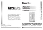
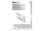
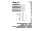
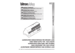
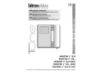
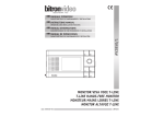
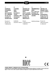
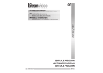
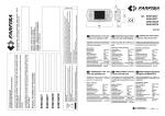
MANUALE ISTRUZIONI
CARATTERISTICHE DI FUNZIONAMENTO E INSTALLAZIONE
OPERATING AND INSTALLATION FEATURES
MANUEL D’INSTRUCTIONS
CARATERISTIQUES DE FONCTIONNEMENT ET INSTALLATION
GEBRAUCHSANWEISUNG
BETRIEBSDATEN UND INSTALLATION
MANUAL DE ISTRUCCIONES
CARACTERÍSTICAS DE FUNCIONAMIENTO E INSTALACIÓN
AV2058/51 • AV2058/52
INSTRUCTIONS MANUAL
KIT CITOFONICO T-LINE 4+N 12Vca - MONO E BI-FAMILIARE
DOOR-PHONE KIT 4+N T-LINE 12Vac - ONE-FAMILY TWO-FAMILY
AUDIO SET 4+N T-LINE 12Vca - UNIFAMILIAR BIFAMILIAR
AUDIO KIT 4+N T-LINE 12Vac - EINFAMILIEN ZWEIFAMILIEN
AUDIO KIT 4+N T-LINE 12Vca - UNIFAMILIAR BIFAMILIAR
DS90335-002
LBT90206
1
1
2d
Rif.
FUNZIONE - FUNCTION - FONCTION
FUNKTION - FUNCIÓN
DISTANZE - DISTANCES - DISTANCES
ENTFERNUNG - DISTANCIA
50 mt
200 mt
100 mt
Ø
Sez.
mm²
Ø
Sez.
mm²
300 mt
Ø
Sez.
mm²
Ø
Sez.
mm²
1
Altoparlante - Loudspeaker - Haut-parleur
Lautsprecher - Altavoz
0,6
0,3
0,8
0,5
1
0,75
1,4
1,5
2
Microfono - Microphone - Microphone
Mikrophono - Micrófono
0,6
0,3
0,8
0,5
1
0,75
1,4
1,5
6
Comune fonica - Speech common - Commun phonie
Gemeinsame Sprachleitung - Común de fonia
0,8
0,5
1
0,75
1,2
1
1,4
1,5
9
Apriporta - Door opener - Gâche - Türöffner - Abrepuerta
0,8
0,5
1
0,75
1,2
1
1,4
1,5
Chiamata - Call - Appel - Ruf - Llamada
0,6
0,3
0,8
0,5
1
0,75
1,4
1,5
Negativo di alimentazione - Negative power
Négatif alimentation - Spaisung negative
Negativo alimentación
1,2
1
-
-
-
-
-
-
Alimentazione - Power supply - Alimentation
Netzversongung - Alimentación
1,2
1
-
-
-
-
-
-
C1-C2-C...
0
~
2f
1,55 - 1,65 m
CONDUTTORE - WIRE - CONDUCTEUR
LEITUNG - CONDUCTOR
2e
2g
2h
2i
m
m
80-90
2
2a
2b
2c
2l
2
DS90335-002
DS90335-002
3
2m
2n
2o
2p
3
LED
RC
4
2q
2r
2s
ITALIANO
2t
2u
DATI TECNICI
2v
♦ Alimentazione:..................................................................................................................... 12 Vca
♦ Dimensioni appoggio pulsantiera: .......................................................................... 190 x 100 x 36 mm
♦ Dimensioni appoggio citofono: ...............................................................................220 x 86 x 53 mm
GENERALITA’
I kit villa (4 + n) T-LINE serie AV2058 sono stati progettati per ottenere dei kit d’appoggio con ingombri ridotti
(190 x 100 x 36 mm) e alimentati a 12Vac.
Le funzioni principali del dispositivo sono:
1) Amplificazione delle fonie in entrambi i sensi
2) Generazione delle note di chiamata sia per la chiamata da posto esterno sia per la chiamata al piano
3) Conferma acustica di avvenuta chiamata
4) Funzione di disgiuntore fonico per impianti con segreto di conversazione
4
DS90335-002
DS90335-002
5
Se nell’impianto si verificasse un innesco Larsen (fischio), ridurre leggermente entrambi i volumi, per
eliminarlo
CONTENUTO DELLA CONFEZIONE E RICAMBI
Codice di riferimento
Pulsantiera citofonica 1 tasto AV1878/10
Pulsantiera citofonica 2 tasti AV1878/12
Posto esterno AV2058/100
Citofono serie T-LINE AV1407/001
Trasformatore 16VA AN1299
Tasselli con viti
Libretto istruzioni
AV2058/51
1
0
1
1
1
5
1
AV2058/52
0
1
1
2
1
5
1
COMPONIBILITA’
PROTEZIONE AL CORTOCIRCUITO SULLA CHIAMATA
Un eventuale cortocircuito sui morsetti di chiamata, farà intervenire la protezione in corrente che interrompe
le chiamate per alcuni secondi. Trascorso tale tempo, il posto esterno sarà nuovamente in grado di generare
una nuova chiamata; al perdurare del cortocircuito il ciclo si ripete.
Per KIT mono-familiare AV2058/51
Collegare il morsetto C del posto esterno su un capo del tasto montato sulla pulsantiera AV1878/10.
Collegare il morsetto “C7” del citofono T-LINE AV1407/002 sull’altro capo del tasto di chiamata
INSTALLAZIONE (Fig. 2)
Per KIT bi-familiare AV2058/52
Collegare il morsetto C del posto esterno su un capo dei due tasti montati sulla pulsantiera AV1878/12 creando
un comune di chiamata tramite un ponticello di filo.
Collegare il morsetto “C7” del primo citofono T-LINE AV1407/002 sull’altro capo del tasto di chiamata dell’utente
P1.
Collegare il morsetto “C7” del secondo citofono T-LINE AV1407/002 sull’altro capo del tasto di chiamata
dell’utente P2.
MORSETTI DI COLLEGAMENTO
Alimentazione 12 Vca dal trasformatore AN1299
Negativo alimentazione dal trasformatore AN1299
Chiamata al piano
Comune pulsanti (chiamata citofonica)
Altoparlante colonna
Microfono colonna
Massa citofonica (morsetto 6 del citofono AV1407/001)
COLLEGAMENTO PULSANTI PER CHIAMATA CITOFONICA A RONZATORE
Il corretto collegamento dei due conduttori sul morsetto “–” è di fondamentale importanza, al fine
di evitare ronzii.
COLLEGAMENTI
Per quanto riguarda i collegamenti, è opportuno tenere presente alcune regole fondamentali:
- rispettare accuratamente le sezioni indicate nella tabella. (Fig. 1).
- evitare di posare i cavi dell’impianto vicino a quelli della normale rete elettrica (almeno 30 cm di
distanza).
- collegare i fili di massa esattamente come indicato negli schemi d’impianto per evitare ronzii.
Posizionare il trasformatore ad una distanza massima dal Posto Esterno, di 20 mt.
Utilizzare per la connessione dei terminali ~ e 0 dei conduttori da 1 mm². Rispettare inoltre scrupolosamente
i collegamenti indicati sullo schema, al fine di evitare ronzii sulla fonia
REGOLAZIONE DEI VOLUMI (Fig. 2t)
Il posto fonico esterno, viene regolato in fase di produzione sui valori ottimali, per un impianto di media
grandezza.
Talvolta, può rendersi necessario variare tale regolazione.
In tal caso procedere come segue:
- Volume esterno: agire sul trimmer EXT in senso orario, per aumentare il volume ed in senso opposto per
ridurre il volume.
- Volume interno: agire sul trimmer INT in modo analogo al precedente.
6
Se la chiamata citofonica viene inviata al citofono, il posto esterno genera una nota di conferma; tale nota può
essere disabilitata, aprendo il Jumper “RC” vicino alla morsettiera del posto esterno, come indicato in Fig. 3.
COLLEGAMENTO PULSANTI PER CHIAMATA CITOFONICA ELETTRONICA
Il Kit T-LINE serie AV2058 (4+N) è disponibile nelle configurazioni:
- Mono-familiare 1 tasto AV2058/51.
- Bi-familiare 2 tasti AV2058/52.
~
0
P
C
1
2
–
ESCLUSIONE CONFERMA DI CHIAMATA “RC”
DS90335-002
Per KIT mono-familiare AV2058/51
Collegare il morsetto ~ del posto esterno su un capo del tasto montato sulla pulsantiera AV1878/10.
Collegare il morsetto “C7” del citofono T-LINE AV1407/002 sull’altro capo del tasto di chiamata
Per KIT bi-familiare AV2058/52
Collegare il morsetto ~ del posto esterno su un capo dei due tasti montati sulla pulsantiera AV1878/12 creando
un comune di chiamata tramite un ponticello di filo.
Collegare il morsetto “C7” del primo citofono T-LINE AV1407/002 sull’altro capo del tasto di chiamata dell’utente
P1.
Collegare il morsetto “C7” del secondo citofono T-LINE AV1407/002 sull’altro capo del tasto di chiamata
dell’utente P2.
Per i restanti collegamenti elettrici riferirsi agli schemi d’impianto in fondo al manuale
FISSAGGIO CITOFONO AL MURO
1)
2)
Aprire il citofono facendo leva con un cacciavite, nelle apposite feritoie inferiori (Fig. 4).
Dopo aver eseguito i fori nel muro ed inserito i tasselli dati a corredo, far passare i fili di collegamento
nella feritoia centrale. Bloccare con le viti il citofono al muro, utilizzando gli appositi fori asolati.
Successivamente collegare al citofono i conduttori come da schema elettrico.
Per le sezioni dei conduttori elettrici riferirsi alla relativa tabella (Fig. 1).
3) Richiudere il citofono a scatto facendo attenzione a non pizzicare i fili tra i due gusci
DS90335-002
7
ENGLISH
CONNECTIONS
TECHNICAL SPECIFICATIONS
The following rules must be observed for connections:
- Respect the instructions shown in the table (Fig. 1) carefully.
- Avoid installing system wires close to electrical mains wires (they should be at least 30 cm apart).
- Connect the ground wires exactly as shown in the diagrams to avoid buzzing.
♦ Power: ............................................................................................................................... 12 V ac
♦ Surface-mounted panel dimensions: ....................................................................... 190 x 100 x 36 mm
♦ Surface-mounted doorphone dimensions: ..................................................................220 x 86 x 53 mm
INTRODUCTION
The T-LINE series AV2058 villa kits (4 + n) were designed to supply compact support-mounted devices (190 x
100 x 36 mm) powered at 12Vac.
Position the transformer at a maximum distance from the door panel of 20 metres.
Use 1 mm² wires for connecting terminals ~ and 0. Also respect the connections shown on the diagram
to prevent noise.
VOLUME ADJUSTMENT (Fig. 2t)
The entrance panel audio unit settings are optimal for a system of average size by default.
The settings may however need to be changed.
Proceed as follows in such a case
- External volume: turn trimmer EXT clockwise to turn the volume up and anticlockwise to turn it down.
- Internal volume: turn trimmer INT in a similar way.
The main functions of the device are:
1) Two-way audio amplification.
2) Call tone generation for call from both door panel and floor bell
3) Acoustic call confirmation tone.
4) Audio disconnect function for systems with conversation privacy function.
Turn down both volumes slightly if feedback loop howl occurs to eliminate the problem.
CONTENTS OF THE BOX AND SPARE PARTS
Reference code
Doorphone panel 1 button AV1878/10
Doorphone panel 2 buttons AV1878/12
Door panel AV2058/100
Doorphone series T-LINE AV1407/001
Transformer 16VA AN1299
Bolts
Instruction book
AV2058/51
1
0
1
1
1
5
1
AV2058/52
0
1
1
2
1
5
1
The entrance panel generates a confirmation tone when the doorphone call is sent to the doorphone. This tone
may be deactivated by opening the “RC” jumper near the entrance unit terminal board as shown in Fig. 3.
CALL SHORT CIRCUIT PROTECTION
The protection system will cut off calls for a few seconds in the event of a calling terminal short circuit. After
this time, the entrance panel will be able to generate a new call. The cycle will be repeated if the short circuit
persists.
ELECTRONIC DOORPHONE CALL BUTTON CONNECTIONS
MODULARITY
For AV2058/51 one-villa kit
Connect terminal C of the door panel to a terminal of the button fitted on the AV1878/10 panel.
Connect terminal “C7” of the T-LINE AV1407/002 doorphone to the other calling button terminal.
The T-LINE series AV2058 (4+N) kit is available in the following configurations:
- One-villa 1 button AV2058/51.
- Two-villa 2 buttons AV2058/52.
For AV2058/52 two-villa kit
Connect terminal C of the door panel to a terminal of the two buttons fitted on the AV1878/12 panel creating
a call common using a wire jumper.
Connect terminal “C7” of the first T-LINE AV1407/002 doorphone to the other calling button terminal of user
P1.
Connect terminal “C7” of the second T-LINE AV1407/002 doorphone to the other calling button terminal of
user P2.
INSTALLATION (Fig. 2)
CONNECTION TERMINALS
~
0
P
C
1
2
–
“RC” CALL CONFIRMATION EXCLUSION
12 Vac power from AN1299 transformer
Negative power from AN1299 transformer
Floor call
Button common (doorphone call)
Speaker column
Microphone column
Doorphone ground (terminal 6 of AV1407/001 doorphone)
BUZZER DOORPHONE CALL BUTTON CONNECTIONS
For AV2058/51 one-villa kit
Connect terminal ~ of the door panel to a terminal of the button fitted on the AV1878/10 panel.
Connect terminal “C7” of the T-LINE AV1407/002 doorphone to the other calling button terminal.
The correct connection of the two wires to the “-” terminal is crucial to prevent buzzing.
For AV2058/52 two-villa kit
Connect terminal ~ of the door panel to a terminal of the two buttons fitted on the AV1878/12 panel creating
a call common using a wire jumper.
8
DS90335-002
DS90335-002
9
Connect terminal “C7” of the first T-LINE AV1407/002 doorphone to the other calling button terminal of user
P1.
Connect terminal “C7” of the second T-LINE AV1407/002 doorphone to the other calling button terminal of
user P2.
Refer to the system diagrams at the end of the manual for other electrical connections
COMPOSITION
Le Kit T-LINE série AV2058 (4+N) est disponible dans les configurations:
- Mono-famille 1 touche AV2058/51.
- Bi-famille 2 touches AV2058/52.
INSTALLATION
BORNES DE CONNEXION
FIXING OF THE DOOR PHONE TO THE WALL
1)
2)
3)
Open the door phone front cover by prying a screwdriver in the lower slots (Fig. 4).
Drill two holes in the wall, then insert the nogs supplied and pass the connection wires through the
central slit.
Fix the handset to the wall by means of its mounting screws through the appropriate slots.
Then make all connections as indicated in the electrical diagram.
Wires sections are specified in the relevant table (Fig. 1).
Close the door phone and snap it in position being careful not to squeeze the wires between the two
shells
DONNÉES TECHNIQUES
♦ Alimentation : ..................................................................................................................... 12 Vca
♦ Dimensions support platine : ................................................................................ 190 x 100 x 36 mm.
♦ Dimensions support poste audio : ...........................................................................220 x 86 x 53 mm.
CARACTÉRISTIQUES GÉNÉRALES
Les kits villa (4 + n) T-LINE série AV2058 ont été conçues pour obtenir des kits de support assurant un
encombrement réduit (190 x 100 x 36 mm) et alimentés à 12 Vca.
Les fonctions principales de l’élément sont les suivantes :
1) Amplification des phonies dans les deux sens
2) Génération des tonalités d’appel aussi bien pour les appels de la platine extérieure que pour les appels
palier.
3) Validation sonore de l’activation de l’appel
4) Fonction de coupe-circuit phonique pour les installations avec secret
CONTENU DE LA BOÎTE ET PIÈCES DE RECHANGE
10
Alimentation 12 Vca du transformateur AN1299
Négatif alimentation 12 Vca du transformateur AN1299
Appel palier
Commun touches (appel interphone)
Haut-parleur colonne
Microphone colonne
Masse poste audio (borne 6 du poste audio AV1407/001)
La connexion correcte des deux conducteurs sur la borne “–” est d’importance fondamentale pour
éviter tout sifflement.
RACCORDEMENTS
FRANÇAIS
Code de référence
Platine interphone 1 touche AV1878/10
Platine interphone 2 touches AV1878/12
Platine extérieure AV2058/100
Poste audio série T-LINE AV1407/001
Transformateur 16VA AN1299
Chevilles avec vis
Manuel d’instructions
~
0
P
C
1
2
–
AV2058/51
1
0
1
1
1
5
1
AV2058/52
0
1
1
2
1
5
1
DS90335-002
Au niveau des branchements, il convient de respecter plusieurs règles fondamentales:
- respecter scrupuleusement les sections indiquées dans le tableau. (Fig. 1).
- éviter de poser les câbles de l’installation à proximité de ceux du réseau électrique (à une distance d’au
moins 30 cm).
- brancher les fils de masse exactement à l’endroit indiqué par les schémas de l’installation pour éviter tout
sifflement.
Positionner le transformateur à une distance maximum de la platine extérieure de 20 mètres.
Utiliser pour la connexion des bornes ~ et 0 des conducteurs de 1 mm². Respecter scrupuleusement les
branchements indiqués par le schéma, pour éviter tout sifflement sur la phonie
RÉGLAGE DES VOLUMES (Fig. 2t)
La platine phonique extérieure est réglée de série sur des valeurs optimales, pour une installation de dimensions
moyennes.
Il est parfois nécessaire de modifier ce réglage.
Dans ce cas, suivre la procédure décrite ci-dessous :
- Volume extérieur: agir sur le sélecteur EXT dans le sens horaire, de manière à augmenter le volume et dans
le sens inverse pour le diminuer.
- Volume interne: agir sur le levier INT de la même manière.
En présence d’un phénomène d’amorçage Larsen (sifflement), abaisser légèrement les volumes de manière
à éliminer le problème.
EXCLUSION DE LA VALIDATION D’APPEL “RC”
Si l’appel interphone est envoyé à l’interphone, le poste audio génère une tonalité de validation ; cette
tonalité peut être désactivée en coupant la barrette “RC” située à proximité du bornier de la platine extérieure,
conformément aux indications de la Fig. 3.
DS90335-002
11
PROTECTION CONTRE LES COURTS-CIRCUITS SUR L’APPEL
DEUTSCH
Un éventuel court-circuit sur les bornes d’appel provoquera l’intervention du dispositif de protection qui
interrompt les appels pendant plusieurs secondes. Au terme de ce délai, la platine extérieure est à nouveau en
mesure de générer un nouvel appel ; si le court-circuit n’est pas éliminé, le cycle se répète.
CONNEXION DES TOUCHES POUR APPEL INTERPHONE DE TYPE ÉLECTRONIQUE
Pour KIT mono-famille AV2058/51
Raccorder la borne C de la platine extérieure à une extrémité de la touche montée sur la platine AV1878/10.
Raccorder la borne “C7” du poste audio T-LINE AV1407/002 à l’autre extrémité de la touche d’appel
Pour KIT bi-famille AV2058/52
Raccorder la borne C de la platine extérieure à une extrémité de la touche montée sur la platine AV1878/12 de
manière à créer un commun d’appel au moyen d’une barrette en fil.
Raccorder la borne “C7” du premier poste audio T-LINE AV1407/002 à l’autre extrémité de la touche d’appel
de l’utilisateur P1.
Raccorder la borne “C7” du deuxième poste audio T-LINE AV1407/002 à l’autre extrémité de la touche d’appel
de l’utilisateur P2.
TECHNISCHE DATEN
♦ Versorgung: ......................................................................................................................... 12 Vac
♦ Abmessungen Auflage Tastenfeld: .......................................................................... 190 x 100 x 36 mm
♦ Abmessungen Auflage Sprechanlage: .......................................................................220 x 86 x 53 mm
ALLGEMEINES
Die Kit Villa (4 + n) T-LINE Serie AV2058 wurden entwickelt, um Unterstützungs-Kits mit geringem Platzbedarf
zu erzielen (190 x 100 x 36 mm), die mit 12Vac versorgt werden.
Die Hauptfunktionen des Geräts sind:
1) Verstärkung der Phonien in beiden Richtungen
2) Erzeugung der Rufnoten sowohl für den Anruf von der Außenstelle als auch für den Etagenruf
3) Akustische Bestätigung des erfolgten Anrufs
4) Funktion des phonischen Trennschalters mit Mithörsperre
PACKUNGSINHALT UND ERSATZTEILE
CONNEXION DES TOUCHES POUR APPEL INTERPHONE DE TYPE VIBREUR
Bezugscode
Tastenfeld für Sprechanlagen 1 Taste AV1878/10
Tastenfeld für Sprechanlagen 2 Tasten AV1878/12
Außenstelle AV2058/100
Sprechanlage Serie T-LINE AV1407/001
Transformator 16VA AN1299
Dübel mit Schrauben
Bedienungsanleitung
Pour KIT mono-famille AV2058/51
Raccorder la borne ~ de la platine extérieure à une extrémité de la touche montée sur la platine AV1878/10.
Raccorder la borne “C7” du poste audio T-LINE AV1407/002 à l’autre extrémité de la touche d’appel
Pour KIT bi-famille AV2058/52
Raccorder la borne ~ de la platine extérieure à une extrémité de la touche montée sur la platine AV1878/12 de
manière à créer un commun d’appel au moyen d’une barrette en fil.
Raccorder la borne “C7” du premier poste audio T-LINE AV1407/002 à l’autre extrémité de la touche d’appel
de l’utilisateur P1.
Raccorder la borne “C7” du deuxième poste audio T-LINE AV1407/002 à l’autre extrémité de la touche d’appel
de l’utilisateur P2.
Pour le reste des branchements électriques, faire référence aux schémas de l’installation au bas du
manuel.
FIXATION DE LA PLATINE AU MUR
1)
2)
3)
Ouvrir le combiné soulevant la coiffe, en insérant un tournevis dans les fentes inférieures (Fig. 4).
Après avoir fait les trous dans le mur, insérer les chevilles (fournies) et faire passer les fils dans la fente
centrale. Bloquer, à l’aide des vis, le combiné au mur en utilisant les trous appropriés. Brancher ensuite
les fils au combiné, comme indiqué dans le schéma électrique.
Pour les sections des conducteurs se référer à la table relative (Fig. 1).
Refermer le combiné par pression en veillant à ne pas pincer les fils entre les deux coquilles.
AV2058/51
1
0
1
1
1
5
1
AV2058/52
0
1
1
2
1
5
1
AUSLEGUNGEN
Der Kit T-LINE Serie AV2058 (4+N) ist in den folgenden Konfigurationen erhältlich:
- Einfamilienhaus 1 Taste AV2058/51.
- Zweifamilienhaus 2 Taste AV2058/52.
INSTALLATION (Abb. 2)
ANSCHLUSSKLEMMEN
~
0
P
C
1
2
–
Versorgung 12 Vca vom Transformator AN1299
Minuspol vom Transformator AN1299
Etagenruf
Allgemeine Tasten (Sprechanlagenruf)
Lautsprecher Säule
Mikrofon Säule
Masse der Sprechanlage (Klemme 6 der Sprechanlage AV1407/001)
Der korrekte Anschluss der beiden Leiter auf der Klemme “–” ist von ausschlaggebender Wichtigkeit,
um Brummen zu vermeiden.
12
DS90335-002
DS90335-002
13
ANSCHLÜSSE
Was die Anschlüsse betrifft, sind einige grundlegende Regeln zu beachten:
- sorgsam die in der Tabelle auf Seite 1 angegebenen Abschnitte beachten
- vermeiden, die Kabel der Anlage in der Nähe der des normalen Stromnetzes zu verlegen (mindestens 30 cm
Abstand).
- Die Massekabel genau so anschließen wie in den Anlagenplänen angegeben, um Brummen zu vermeiden.
Für KIT für Zweifamilienhäuser AV2058/52
Die Klemme ~ der Außenstelle an ein Ende der beiden auf dem Tastenfeld AV1878/12 montierten Tasten
anschließen und über eine Drahtbrücke einen gemeinsamen Rufkontakt herstellen.
Die Klemme “C7” der ersten Sprechanlage T-LINE AV1407/002 an das andere Ende der Ruftaste des Benutzers
P1 anschließen.
Die Klemme “C7” der zweiten Sprechanlage T-LINE AV1407/002 an das andere Ende der Ruftaste des Benutzers
P2 anschließen.
Den Transformator in einem Abstand von max. 20 m von der Außenstelle positionieren.
Für den Anschluss der Terminale ~ und 0 Leiter mit 1 mm² verwenden. Außerdem streng die im Plan
angegebenen Anschlüsse einhalten, um Brummen auf der Phonie zu vermeiden
Für die verbleibenden elektrischen Anschlüsse beziehen Sie sich auf die Anlagenpläne am Ende der
Bedienungsanleitung.
BEFESTIGUNG DER SPRECHANLAGE AN DER WAND
LAUTSTÄRKEREGELUNG (Abb. 2t)
1)
Die externe Sprechstelle wird in der Herstellungsphase auf optimale Werte für eine mittelgroße Anlage
eingestellt.
Manchmal kann die Anpassung dieser Einstellung erforderlich sein.
In diesem Fall wie folgt vorgehen:
- Externe Lautstärke: den Trimmer EXT im Uhrzeigersinn betätigen, um die Lautstärke zu erhöhen und in
die Gegenrichtung, um die Lautstärke zu verringern.
- Interne Lautstärke: den Trimmer INT wie zuvor beschrieben betätigen.
Die Sprechanlage öffnen, indem ein Schraubenzieher in den entsprechenden unteren Schlitzen als Hebel
eingesetzt wird (Abb. 4).
2) Nachdem die Bohrungen an der Wand angebracht und die in der Lieferung enthaltenen Dübel eingesetzt
wurden, die Anschlussdrähte in den mittleren Schlitz einführen. Mit den Schrauben die Sprechanlage an
der Wand befestigen, indem die entsprechenden Langlöcher verwendet werden.
Anschließend die Leiter gemäß Schaltplan an die Anlage anschließen.
Zur Auswahl der elektrischen Le iter beziehen Sie sich auf die jeweilige Tabelle (Abb. 1).
3) Die Sprechanlage wieder durch Einrasten schließen und dabei darauf achten, die Drähte nicht zwischen
den beiden Teilen einzuklemmen.
Sollte in der Anlage ein Larsen-Effekt (Pfeifen) auftreten, beide Lautstärken leicht verringern, um ihn zu
beseitigen
ESPAÑOL
AUSSCHLUSS DER RUFBESTÄTIGUNG “RC”
Wird der Sprechanlagenanruf an eine Sprechanlage weitergeleitet, erzeugt die Außenstelle einen neuen
Bestätigungston. Dieser Ton kann deaktiviert werden, indem der Jumper “RC” in der Nähe der Klemmenleiste
der Außenstelle geöffnet wird wie in Abb. 3 angegeben.
SCHUTZ VOR KURZSCHLÜSSEN AUF DEM ANRUF
Ein eventueller Kurzschluss auf den Klemmen der Rufleitung führt zu einem Eingreifen des Stromschutzes, der
die Anrufe für einige Sekunden unterbricht. Nach dem Verstreichen dieser Zeit ist die Außenstelle erneut in der
Lage, einen neuen Anruf zu erzeugen. Dauert der Kurzschluss an, wiederholt sich der Zyklus.
ANSCHLUSS DER TASTEN FÜR DEN ELEKTRONSCHEN SPRECHANLAGENRUF
Für KIT für Einfamilienhäuser AV2058/51
Die Klemme C der Außenstelle an ein Ende der auf dem Tastenfeld AV1878/10 montierten Taste anschließen.
Die Klemme “C7” der Sprechanlage T-LINE AV1407/002 an das andere Ende der Ruftaste anschließen
Für KIT für Zweifamilienhäuser AV2058/52
Die Klemme C der Außenstelle an ein Ende der beiden auf dem Tastenfeld AV1878/12 montierten Tasten
anschließen, indem über eine Drahtbrücke ein gemeinsamer Rufkontakt hergestellt wird.
Die Klemme “C7” der ersten Sprechanlage T-LINE AV1407/002 an das andere Ende der Ruftaste des Benutzers
P1 anschließen.
Die Klemme “C7” der zweiten Sprechanlage T-LINE AV1407/002 an das andere Ende der Ruftaste des Benutzers
P2 anschließen.
ANSCHLUSS DER RUFTASTEN DER SPRECHANLAGE AN EINEN SUMMER
Für KIT für Einfamilienhäuser AV2058/51
Die Klemme ~ der Außenstelle an ein Ende der auf dem Tastenfeld AV1878/10 montierten Taste anschließen.
Die Klemme “C7” der Sprechanlage T-LINE AV1407/002 an das andere Ende der Ruftaste anschließen
14
DS90335-002
DATOS TÉCNICOS
♦ Alimentación: ...................................................................................................................... 12 Vca
♦ Dimensiones de apoyo del teclado: ........................................................................ 190 x 100 x 36 mm
♦ Dimensiones de apoyo del interfono: ........................................................................220 x 86 x 53 mm
CARACTERÍSTICAS GENERALES
Los kits para casa (4 + n) T-LINE serie AV2058 fueron diseñados para realizar juegos de apoyo de dimensiones
reducidas (190 x 100 x 36 mm) y alimentados con 12 Vca.
Las funciones principales del dispositivo son:
1) Amplificación de los niveles de sonido en ambas direcciones
2) Generación de las notas de llamada desde microaltavoz y de llamada al piso
3) Confirmación acústica de llamada efectuada
4) Función de disyuntor fónico para sistemas con secreto de conversación
CONTENIDO DE LA CAJA Y REPUESTOS
Código de referencia
Teclado interfónico de 1 tecla AV1878/10
Teclado interfónico de 2 teclas AV1878/12
Microaltavoz AV2058/100
Interfono serie T-LINE AV1407/001
Transformador 16VA AN1299
Tacos con tornillos
Manual de instrucciones
DS90335-002
AV2058/51
1
0
1
1
1
5
1
AV2058/52
0
1
1
2
1
5
1
15
CONFIGURACIONES
PROTECCIÓN CONTRA CORTOCIRCUITOS EN LA LLAMADA
El Kit T-LINE serie AV2058 (4+N) se ofrece en las versiones:
- Monofamiliar de 1 tecla AV2058/51
- Bifamiliar de 2 teclas AV2058/52
Un posible cortocircuito en los bornes de llamada hace intervenir la protección de corriente que interrumpe las
llamadas durante algunos segundos. Cuando se cumple dicho lapso de tiempo, el microaltavoz está nuevamente
en condiciones de generar otra llamada; el ciclo se repetirá mientras haya un cortocircuito.
INSTALLACIÓN (Fig. 2)
CONEXIÓN DE PULSADORES PARA LLAMADA INTERFÓNICA ELECTRÓNICA
BORNES DE CONEXIÓN
Para KIT monofamiliar AV2058/51
Conectar el borne C del microaltavoz en un extremo de la tecla montada en el teclado AV1878/10.
Conectar el borne “C7” del interfono T-LINE AV1407/002 en el otro extremo de la tecla de llamada
~
0
P
C
1
2
–
Alimentación 12 Vca mediante el transformador AN1299
Negativo alimentación desde el transformador AN1299
Llamada al piso
Común pulsadores (llamada interfónica)
Altavoz columna
Micrófono columna
Masa interfónica (borne 6 del interfono AV1407/001)
Es sumamente importante la correcta conexión de los dos conductores en el borne “-“ para evitar
los zumbidos.
CONEXIONES
Por lo que se refiere a las conexiones, es conveniente recordar algunas reglas fundamentales:
- respetar meticulosamente las secciones indicadas en la tabla (Fig. 1).
- evitar hacer pasar los cables del sistema cerca de los de la red eléctrica normal (al menos 30 cm de
distancia).
- conectar los conductores de masa exactamente como se indica en los diagramas del sistema, para evitar
los zumbidos.
Colocar el transformador a una distancia máxima de 20 m del Microaltavoz.
Para la conexión de los terminales ~ y 0, utilizar conductores de 1 mm². También se deben respetar
meticulosamente las conexiones indicadas en los diagramas del sistema, para evitar los zumbidos en la
transmisión de voz.
AJUSTE DEL VOLUMEN (Fig. 2t)
Para KIT bifamiliar AV2058/52
Conectar el borne C del microaltavoz en un extremo de las dos teclas montadas en el teclado AV1878/12,
creando un común de llamada mediante un puente de conductor.
Conectar el borne “C7” del primer interfono T-LINE AV1407/002 en el otro extremo de la tecla de llamada del
usuario P1.
Conectar el borne “C7” del segundo interfono T-LINE AV1407/002 en el otro extremo de la tecla de llamada
del usuario P2.
CONEXIÓN DE PULSADORES PARA LLAMADA INTERFÓNICA DE ZUMBADOR
Para KIT monofamiliar AV2058/51
Conectar el borne ~ del microaltavoz en un extremo de la tecla montada en el teclado AV1878/10.
Conectar el borne “C7” del interfono T-LINE AV1407/002 en el otro extremo de la tecla de llamada
Para KIT bifamiliar AV2058/52
Conectar el borne ~ del microaltavoz en un extremo de las dos teclas montadas en el teclado AV1878/12,
creando un común de llamada mediante un puente de conductor.
Conectar el borne “C7” del primer interfono T-LINE AV1407/002 en el otro extremo de la tecla de llamada del
usuario P1.
Conectar el borne “C7” del segundo interfono T-LINE AV1407/002 en el otro extremo de la tecla de llamada
del usuario P2.
Consultar las otras conexiones en los diagramas del sistema que se encuentran al final del manual
FIJACIÓN DEL INTERFONO EN LA PARED
Los niveles de volumen del microaltavoz ya están regulados de fábrica con los valores ideales para un sistema
de medias dimensiones.
A veces puede ser necesario variar el ajuste.
En dicho caso, actuar de la siguiente manera:
- Volumen exterior: girar el trimmer EXT en el sentido de las agujas del reloj para aumentar el volumen y,
en el sentido contrario, para reducirlo.
- Volumen interior: accionar el trimmer INT de la misma manera que en el caso anterior.
Si en el sistema se produce un efecto de reacción acústica “Larsen” (silbido), reducir ligeramente el
volumen interior y exterior para eliminarlo.
1)
Abrir el interfono haciendo palanca con un destornillador en las correspondientes ranuras inferiores (Fig.
4).
2) Después de realizar los orificios en la pared y de colocar los tacos entregados con el equipo, hacer pasar
los cables de conexión por la ranura central. Fijar el interfono en la pared con los tornillos, utilizando los
correspondientes orificios rebordeados.
Luego, conectar los conductores en el interfono como se indica en el diagrama eléctrico.
Consultar las secciones de los conductores eléctricos en la tabla correspondiente (Fig. 1)
3) Cerrar otra vez el interfono (a presión), prestando atención a no pellizcar los cables entre las dos
cubiertas.
EXCLUSIÓN DE LA CONFIRMACIÓN DE LLAMADA “RC”
Si la llamada interfónica se envía al interfono, el microaltavoz genera una nota de confirmación; dicha nota
se puede desactivar abriendo el puente “RC” que está cerca del tablero de bornes del microaltavoz, como se
indica en la Fig. 3.
16
DS90335-002
DS90335-002
17
179 233 71
179 233 71/B
IMPIANTO CITOFONICO (Kit AV2058/51) CON 1 POSTO ESTERNO, 1 UTENTE - COLLEGAMENTO SUONERIA SUPPLEMENTARE
(Kit AV2058/51) DOORPHONE SYSTEM WITH 1 VISITOR PANEL, 1 USER - CONNECTION ADDITIONAL RINGER
SISTEME AUDIO (Kit AV2058/51) AVEC UNE PLATINE D’ENTREE, 1 UTILISATEUR - RACCORDEMENT SONNERIE ADDITIONNELLE
(Kit AV2058/51) TÜRSPRECHANLAGE MIT 1 TÜRSTATION, 1 BENUTZER - ZUSÄTZLICHER WECKER DES ANSCHLUßES
(Kit AV2058/51) SISTEMA DE AUDIO CON 1 PLACA EXTERIOR, 1 USUARIO - CONEXION DE TIMBRE ADICIONAL
IMPIANTO CITOFONICO (Kit AV2058/51) CON 1 POSTO ESTERNO, 2 UTENTI
(Kit AV2058/51) DOORPHONE SYSTEM WITH 1 VISITOR PANEL, 2 USERS
SISTEME AUDIO (Kit AV2058/51) AVEC UNE PLATINE D’ENTREE, 2 UTILISATEURS
(Kit AV2058/51) TÜRSPRECHANLAGE MIT 1 TÜRSTATION, 2 BENUTZER
(Kit AV2058/51) SISTEMA DE AUDIO CON 1 PLACA EXTERIOR, 2 USUARIOS
All rights reserved - Diritti riservati a Norma di Legge
All rights reserved - Diritti riservati a Norma di Legge
Tasto chiamata al piano
Call button at the floor
Bouton d'appel au plancher
Anruftaste am Fußboden
Botón de la llamada en el piso
Tasto chiamata al piano
Call button at the floor
Bouton d'appel au plancher
Anruftaste am Fußboden
Botón de la llamada en el piso
C7
P
1
2
9
6
Au
Au
C7
P
1
2
9
6
Au
AV 1407/001
Au2
C7
P
1
2
9
6
Au
Au
AV 1407/001
A
B
C
AN 7817
( SA 100 )
AV 2058/100
(4+1)
EXT
AV 2058/100
OPZIONALE
OPTIONAL
OPTIONNEL
OPTIONAL
OPCIONAL
1
2
AV1878/12
EXT
9
6
MODULO AUDIO
AUDIO MODULE
MODULE AUDIO
AUDIO MODUL
MÓDULO AUDIO
Au
Au2
C7
P
1
2
9
6
Au
Au
AV 1407/001
INT
INT
2
1
c
p
0
0 P C 1 2
alt
0 P2 C 1
-
-
RC
RC
-
RETE
MAINS
MAIN
NETZ
RED
RETE
12
MAINS
0
MAIN
NETZ
AN 1299
RED
12
0
AN 1299
Serratura
Lock
Serrure
Tür-öffner
Cerradura
Serratura
Lock
Serrure
Tür-öffner
Cerradura
Apriporta Esterno
External Door Opener
Bouton de sortie
Externer Tür-öffner
Externo Abre-puerta
Apriporta Esterno
External Door Opener
Bouton de sortie
Externer Tür-öffner
Externo Abre-puerta
18
C7
P
AV1878/10
MODULO AUDIO
AUDIO MODULE
MODULE AUDIO
AUDIO MODUL
MÓDULO AUDIO
(4+1)
DS90335-002
DS90335-002
19
Bitron Video adotta una politica di continuo sviluppo. Bitron Video
si riserva il diritto di effettuare modifiche e miglioramenti a qualsiasi
prodotto descritto nel presente documento senza preavviso.
Bitron Video follows a policy of continuous evolution of its products.
Therefore Bitron Video reserves the right to introduce changes or
modifications all its products in any moment and without prior
notice.
Bitron Video applique une mèthode de dèveloppement continu.
Par conséquent, Bitron Video se réserve le droit d’apporter des
changements et des améliorations à tout produt décrit dans ce
document, sans aucun préavis.
Bitronvideo verfolgt eine Strategie der kontinuierlichen Entwicklung
und behält sich daher das Recht auf Änderungen und Verbesserungen
an jedem in dieser Anleitung beschriebenen Produkt ohne
Vorankündigung vor.
Bitronvideo sigue una política de constante desarrollo; por lo tanto,
se reserva el derecho de aportar modificaciones y mejoras a cualquier
producto descrito en este documento sin aviso previo.
BITRON VIDEO s.r.l.
http://www.bitronvideo.com
e-mail : [email protected]
DS90335-002
LBT90206