1
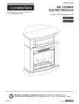
INSTRUCTION MANUAL ENCLOSED
MANUEL D'INSTRUCTIONS À L’INTÉRIEUR
MANUAL DE INSTRUCCIONES ADJUNTO
STOP
ATTENTION
STOP
IF YOU HAVE ANY PROBLEMS OR QUESTIONS, EMAIL
OR CALL CUSTOMER SERVICE BEFORE YOU RETURN
THIS PRODUCT TO THE STORE WHERE IT WAS PURCHASED.
For Customer Service: www.twinstarhome.com
in English Call: 866-661-1218
in Spanish Call: 866-661-1218
in French Call: 866-374-9203
PARE
ATENCIÓN
PARE
SI TIENE ALGÚN PROBLEMA O PREGUNTAS,
ENVÍE UN MENSAJE DE CORREO ELECTRÓNICO O LLAME AL SERVICIO
DE ATENCIÓN AL CLIENTE ANTES DE DEVOLVER
ESTE PRODUCTO A LA TIENDA EN LA QUE LO COMPRÓ.
Servicio de atención al cliente: www.twinstarhome.com
Línea para llamadas en inglés: 866-661-1218
Línea para llamadas en español: 866-661-1218
Línea para llamadas en francés: 866-374-9203
STOP
ATTENTION
STOP
POUR TOUT PROBLÈME OU TOUTE QUESTION,
ENVOYEZ UN COURRIEL AU SERVICE À LA CLIENTÈLE OU APPELEZ LE
SERVICE À LA CLIENTÈLE AVANT DE RETOURNER
CE PRODUIT OÙ VOUS L’AVEZ ACHETÉ.
Pour le service à la clientèle : www.twinstarhome.com
Pour appeler en anglais, composez le 866-661-1218
Pour appeler en espagnol, composez le 866-661-1218
Pour appeler en français, composez le 866-374-9203
INSTRUCTION MANUAL ENCLOSED
MANUEL D'INSTRUCTIONS À L’INTÉRIEUR
MANUAL DE INSTRUCCIONES ADJUNTO
WOOD FIREPLACE MANTEL
18DE9033
WOOD MANTEL ASSEMBLY INSTRUCTIONS
Wall Mantel
Corner Mantel
PARTS LIST
PART
A
B
C
D1
D2
E
F
G
H
I
L
M
T
W
K
R
J
X
Y
Q
P
U
N
O
Y1
V
Z
Y2
Y3
Z1
DESCRIPTION
PARTS
Hearth/Base
Center Left Side Panel
Center Right Side Panel
Center Shelf
Center Top Panel
Left Side Panel
Right Side Panel
Mantel/Top
Center Left Front Panel
Center Right Front Panel
Left Front Panel
Right Front Panel
Center Front Panel
Wood Shelf
Side Back Panel
Center Back Panel
Left Front Door
Right Front Door
Securing Block
"L" corner brace
Top corner extension
HARDWARE
Camlock (U-1,U-2)
Wood Dowel
Shelf Pin
Screw
Knob (with bolt)
Euro Hinge (Z-a,Z-b)
Screw 3.75" x 25mm
Screw 3.75" x 40mm
Touch-Up Pen (W3304)
For Customer Service:
Twin-Star International, Inc.
Delray Beach, FL 33445
E-1
Made in China
Printed in China
QUANTITY
www.twinstarhome.com
In English call: 866-661-1218
In French call: 866-374-9203
In Spanish call: 866-661-1218
1
1
1
1
1
1
1
1
1
1
1
1
1
4
2
1
1
1
1
1
1
31
37
16
36
2
4
10
12
1
AT T E N T I O N
ALSO Requires-Electric
Fireplace Insert with Heater
PLEASE READ AND FOLLOW ALL SAFETY TIPS
GETTING STARTED
1. Before assembly, CAREFULLY use scissors or utility knife to cut and unwrap all parts. Make sure you do
not discard the hardware.
2. Make sure that you have all the parts listed. If you are missing any parts please email Customer Service:
twinstarhome.com or call 1-866-661-1218 in English, 1-866-374-9203 in French or
1-866-661-1218 in Spanish. Please identify the parts you need and model number. Make sure to include
your name and address.
CAUTION:
DO NOT MOVE MANTEL OR INSERT WHILE PLUGGED INTO POWER SUPPLY.
HELPFUL HINTS
• Some steps are more easily handled with two adults.
• Attach the f replace insert to the completed wood mantel last. INSTALL INSERT IN FROM THE BACK
OF THE FIREPLACE SO AS NOT TO SCRATCH THE HEARTH/BASE.
• Use care in assembling your new f replace, take your time and use the hardware provided and a quality
Phillips head screwdriver. NEVER OVER TIGHTEN BOLTS.
• Do not sit on any part of the mantel.
CARE & CLEANING
1. Dust your f replace regularly with a soft non-lint producing cloth or household dusting product.
2. You can clean your f replace with a gentle non-abrasive household cleaner. Make sure to dry your
f replace immediately with a soft cloth or towel.
Now it is time to assemble your Fireplace.
All panels are labeled Left and Right as
viewed from the front of unit.
To avoid scratching the finish of
your new mantel place all parts on a
scratch free surface such as a rug or
carpet.
Camlock installation.
For correct installation, screw U-1 must be
inserted and tightened in the pre-drilled hole.
Camlock U-2 must be inserted into the
pre-drilled hole with the cross positioned in the
direction of screw U-1.
E-2
U-1
1. Locate the Left Front Panel (L), Center Left
Side Panel (B), and set out face down on a
scratch-free surface. Insert Wood Dowel (N)
and screw (U-1) into the holes in the Left Front
Panel, make sure to tighten (U-1). Push Left
Front Panel (L) snug to the Center Left Side
Panel (B). Use a Phillips head screwdriver to
tighten (U-2).
Repeat with Right Front Panel (M) and
Center Right Side Panel (C).
N
U-2
Right
Front M
Panel
Left
Front L
Panel
C
B
Center
Right
Side
Panel
2. Locate the Center Top Panel (D2), Center
Shelf (D1), and set out face down on a
scratch-free surface. Insert Wood Dowel
(N) and screw (U-1) into the holes in the
Center Front Panel, make sure to tighten
(U-1). Push Center Top Panel (D2) snug to
the Center Shelf (D1). Use a Phillips head
screwdriver to tighten (U-2).
U-2
N
U-1
Center Top
Panel
D2
D1
Center Shelf
E-3
Center
Left
Side
Panel
N
U-1
3. Insert Wood Dowel (N) and screw (U-1) into
the holes in the Center Left Side Panel (B),
make sure to tighten (U-1). Push Center Left
Side Panel (B) snug to the Center Shelf (D1).
Use a Phillips head screwdriver to tighten
(U-2).
Repeat with Center Right Side Panel (C).
U-2
D1
B
C
4. Locate the Center Left Front Panel (H), Center
Right Front Panel (I), Center Front Panel (T)
and set out face down on a scratch-free surface.
Insert Wood Dowel (N) and Screw (U-1) into
the holes in the front panels, make sure to
tighten (U-1). Push Center Left Front Panel
(H) and Center Right Front Panel (I) snug to
the Center Front Panel (T). Use a Phillips head
screwdriver to tighten (U-2).
U-1
U-2
Center Front
Panel
T
I Center
Right
Front
Panel
E-4
N
Center
H Left
Front
Panel
5. Attached the front panel assembly to the
completed assembly from step 2, tighten Screw
(Y2) through the pre-drilled holes.
MAKE SURE
TO USE THE
SCREWS Y2
FOR THIS
STEP
Y2
6. Locate Hearth/Base (A) and lie down on
scrach free surface, Insert wood dowel (N)
into the Hearth/Base, push the completed
assembly from the step 4 to the Hearth/Base as
show in diagram, tighten Screw (Y3) through
the pre-drilled holes.
7. Insert wood dowel (N) into the Hearth/Base,
push the Left Side Panel (E) and Right Side
Panel (F) to the Hearth/Base as show in
diagram, tighten Screw (Y3) through the
pre-drilled holes.
Y3
Right
Side
Panel
F
N
N
E
Left
Side
Panel
E-5
N
A
Hearth/Base
N
8. Insert one Wood Dowel (N) and Screw
(U-1) into each of the pre-drilled holes in the
underside of Mantel/Top (G) and lay f nished
side up on top of completed assembly. From
the inside, attach the Mantel use a Phillips
head screwdriver to tighten (U-2).
U-1
U-2
G
Mantel/Top
9. Locate Side Back Panel (K) and Center Back
Panel (R), attach to the back of the completed
assembly from step 8. Use a Phillips Head
screw driver, tighten screws (Y1) through
the pre-drilled holes in the Back Panels to the
completed assembly.
Y1
K
Side
Back
Panel
E-6
R
Center Back
Panel
K
Side
Back
Panel
10. Locate Right Front Door (X) and Left Front
Door (J). Slide door hinge keyhole into panel
hinge bracket. (Diagram 1)
Use a Phillips Head Screwdriver to tighten
screws.(Diagram 2)
TO ADJUST HINGES
To adjust door forward or backward change
keyhole slot position. (As Shown In
Diagram 3a)
To adjust door right or left loosen / tighten
screw. (As Shown In Diagram 3b)
To adjust door up or down adjust bracket
height.(As Shown In Diagram 3c).
11. Attach the Knob (V) to the Left Front Door
(J) and Right Front Door (X), use the bolts
attached through the pre-drilled holes in the
doors. Then use a Phillips Head Screwdriver
to tighten the bolts.
12. Choose desired height of shelf and place the
four Shelf Pins (O) into same height shelf
holes inside side Panels. Insert Wood Shelf
(W), allow Wood Shelf (W) to rest on the
Shelf Pins (O).
a b
c
V
Knob
X Right
Front
Door
J
Left
Front
Door
Wood
Shelf
W
O
Shelf
Pin
E-7
PLEASE READ ALL “ELECTRIC
FIREPLACE INSERT” INSTRUCTIONS
PRIOR TO INSTALLING ELECTRIC
INSERT IN YOUR COMPLETED
FIREPLACE MANTEL. INSTALL
THE INSERT IN YOUR FIREPLACE
13. Lift insert carefully into the back of the unit
and center in the insert opening. Do not
drag insert across Hearth/Base (A) as it may
scratch your unit.
14. Insert Wood Dowel (N) and Screw (U-1) into
the holes in the Hearth/Base, make sure to
tighten (U-1). Attach Securing Block (Y)
to hold insert from back. Use a phillips head
screwdriver to tighten (U-2).
MOVE YOUR COMPLETED UNIT
ONLY SHORT DISTANCES. MOVE
COMPLETED UNIT WITH GREAT
CARE. IT TAKES TWO PEOPLE TO
MOVE COMPLETED UNIT INTO ITS
FINAL POSITION.
Install
Insert
From
Back
Completed
Unit
Electric Fireplace
Insert
U-2
Securing
Block
Y
15. Locate the “L” Corner Brace (Q), Top Corner
Extension (P) and set out face down on a
scratch-free surface.
Insert one Wood Dowel (N) and Screw (U-1)
into the the holes at the rear of the Top Corner
Extension (P), make sure to tighten (U-1).
Push the “L” Brace snug to Top Corner
Extension (P). Use a Phillips head
screwdriver to tighten (U-2). Set part aside.
N
"L" Corner
Brace
Q
U-2
N
U-1
N
P
E-8
Top Corner
Extension
U-1
16. Tighten Screw (U-1) into the holes in the back
of the mantel top and the bottom of the Base.
Insert the Wood Dowel (N) into the holes.
Attach the Completed assembly from step 15
into place at the back of Mantel. Use a
Phillips head screwdriver to tighten (U-2).
Twin-Star International, Inc.
Delray Beach, FL 33445
In English: 1-866-661-1218
In French: 1-866-374-9203
In Spanish: 1-866-661-1218
Model# 18DE9033
Made in China
Printed in China
2010,Twin-Star International, Inc.
E-9
N
N
U-1
U-2
MANTEAU DE FOYER EN BOIS
18DE9033
INSTRUCTIONS D’ASSEMBLAGE POUR LE MANTEAU EN BOIS
MANTEAU AVEC COIN
MANTEAU SANS COIN
LISTE DES PIÈCES
PIÈCE
DESCRIPTION
QUANTITÉ
PIÈCES
A
B
C
D1
D2
E
F
G
H
I
L
M
T
W
K
R
J
X
Y
Q
P
U
N
O
Y1
V
Z
Y2
Y3
Z1
Âtre/Base
Panneau central de gauche
Panneau central de droite
Étagère centrale
El Centro de Panel de
Panneau latéral gauche
Panneau latéral droite
Manteau/Partie supérieure
Panneau avant central de gauche
Panneau avant central de droite
Panneau avant de gauche
Panneau avant de droite
Panneau central avant
Tablette en bois
Panneau arrière latéral
Panneau arrière central
Porte avant de gauche
Porte avant de droite
Bloc De Retenue
Écharpe en « L »
Prolongation de l'angle supérieur
QUINCAILLERIE
Camloc (U-1,U-2,)
Goujon en bois
Cheville de la tablette
Vis
Bouton (avec boulon)
Euro Charnière (Z-a,Z-b)
Vis 3.75"x 25mm
Vis 3.75"x 40mm
Crayon pour retouches (W3504)
Pour le service à la clientèle
:
Twin-Star International, Inc. www.twinstarhome.com
Delray Beach, FL 33445
pour le service en anglais, composez le 866-661-1218
F-1
Fabriqué en Chine
Imprimé en Chine
pour le service en français, composez le 866-374-9203
pour le service en espagnol, composez le 866-661-1218
1
1
1
1
1
1
1
1
1
1
1
1
1
4
2
1
1
1
1
1
1
31
37
16
36
2
4
10
12
1
AT T E N T I O N
Exige aussi -foyer
encastrable électrique avec
Chauffage
VEUILLEZ LIRE ET SUIVRE TOUS LES CONSEILS DE SÉCURITÉ
AVANT DE COMMENCER
1. Avant l’installation, utilisez des ciseaux ou un couteau universel pour couper et déballer tous les
composants. Faites ATTENTION de ne pas endommager le manteau. Assurez-vous de ne pas jeter la
quincaillerie d’installation incluse.
2. Assurez-vous d’avoir toutes les pièces indiquées sur la liste. S'il manque des pièces, veuillez envoyer un
courriel au service à la clientèle à l’adresse twinstarhome.com ou composez les numéros suivants :
pour le service en anglais : 1-866-661-1218; pour le service en français : 1-866-374-9203 ou pour le
service en espagnol-866-661-1218. Veuillez indiquer les pièces manquantes ainsi que le numéro de
modèle. Assurez-vous d’inclure vos nom et adresse.
ATTENTION
NE PAS DÉPLACER LE MANTEAU OU LE FOYER TANT QU’IL EST BRANCHÉ.
CONSEILS UTILES
• Certaines étapes seront plus faciles à réaliser avec l’aide d’un autre adulte.
• La dernière étape consistera à lier le manteau entièrement monté au foyer. INSTALLEZ LE FOYER
ENCASTRABLE EN LE DÉPOSANT PAR L’ARRIÈRE DU MANTEAU POUR ÉVITER
D’ÉGRATIGNER L’ÂTRE/BASE DU MANTEAU.
• Faites attention lorsque vous assemblez le foyer et le manteau. Prenez votre temps et utilisez la
quincaillerie fournie, ainsi qu’un tournevis cruciforme. NE PAS TROP SERRER LES BOULONS.
• Ne vous asseyez pas sur aucune partie du manteau!
SOINS ET NETTOYAGE
1. Époussetez régulièrement votre FOYER avec un chiffon doux non pelucheux ou un produit domestique
pour l’époussetage.
2.Vous pouvez nettoyer le foyer avec un nettoyant domestique doux non abrasif. Assurez-vous de l’essuyer
immédiatement avec un linge doux ou une serviette.
Pour un assemblage sans jeu, chaque
boulon devrait comporter une
rondelle plate.
Pour éviter d’égratigner le fini du
nouveau meuble, placer toutes les
pièces sur une surface parfaitement
lisse comme une couverture ou un
tapis.
Camleck instàllation.
For installation correcte, U vis-1 doit être
inséré et renforcés dans le trou déjà foré.
U Camlock-2 doit être insérée dans le trou
déjà foré avec la croix placée dans la direction
d'U vis-1.
F-2
U-1
1. Trouvez le panneau avant de gauche (L), le
panneau central de gauche (B), et déposez-les
côté f ni vers le sol, sur une surface où ils ne
risquent pas de se rayer. Insérez le goujon en
bois (N) et la vis (U-1) dans les trous du
panneau avant de gauche. Assurez-vous de bien
serrer (U-1). Appuyez sur le Panneau avant de
gauche (I) jusqu’à ce qu’il soit bien assis contre
le panneau central de gauche (B). Utilisez un
tournevis cruciforme pour serrer (U-2).
Répétez pour le panneau avant de droite (M)
et le panneau central de droite (C).
N
U-2
Panneau
avant de
droite
Panneau
central de
gauche
Panneau
avant de
gauche L
M
C
B
Panneau
central de
droite
2. Trouvez le Panneau avant central (D2) et
l’Étagère centrale (D1), et déposez-les côté f ni
vers le sol, sur une surface où ils ne risquent
pas de se rayer. Insérez le Goujon en bois (N)
et la vis (U-1) dans les trous du panneau avant
central. Assurez-vous de bien serrer (U-1).
Appuyez sur le Panneau avant central (D2)
jusqu’à ce qu’il soit bien assis contre l’Étagère
centrale (D1). Utilisez un tournevis cruciforme
pour serrer (U-2).
U-2
N
U-1
Panneau avant
central
D2
D1
Étagère
centrale
F-3
N
U-1
3. Insérez le goujon en bois (N) et la vis (U-1)
dans les trous du panneau central de gauche
(B). Assure-vous de bien serrer (U-1).
Appuyez sur le panneau central de gauche (B)
jusqu’à ce qu’il soit bien assis contre l’étagère
centrale (D1). Utilisez un tournevis cruciforme
pour serrer (U-2).
Répétez pour le panneau central de
droite (C).
U-2
D1
B
C
4. Repérer le panneau avant central de gauche
(H), le panneau avant central de droite (I) et le
panneau avant central (T) et les placer face au
sol sur une surface parfaitement lisse. Insérer
un goujon en bois (N) et une vis (U-1) dans
les trous des panneaux avant et s’assurer de
bien serrer la vis (U-1). Pousser uniformément
le panneau avant central de gauche (H) et le
panneau avant central de droite (I) contre le
panneau avant central (T). Utiliser un tournevis
à pointe cruciforme pour serrer le tout (U-2).
U-1
U-2
panneau avant
central
T
I panneau
avant
central de
droite
F-4
N
panneau
H avant
central de
gauchel
5. Attached the front panel assembly to the
completed assembly from step 2, tighten Screw
(Y2) through the pre-drilled holes.
VEIUEZ À
UTICISER
LES VIS PLUS
COURTES Y2
POUR CETTE
CETTE ÉTAPE
6. Localiser Base (A) et de s'allonger sur la
surface libre scrach, Insérer goujon en bois (N)
dans le Base de Hearth, poussez l'assemblage
terminé de l'étape 4 à la Base comme le
montrent le diagramme, serrer la vis (Y3) à
travers les trous pré-percés.
7. Bâton de bois Insert (N) dans le Base de
Base, poussez le panneau latéral gauche (E) et
du panneau latéral droit (F) à la Base comme le
montrent le diagramme, serrer la vis (Y3) à
travers les trous pré-percés.
Y2
Y3
panneau
latéral
droit
F
N
E
panneau
latéral
N
gauche
F-5
N
A
Base
8. Insérer un goujon en bois (N) dans chacun
des trous percés préalablement, lesquels sont
situés sur les bords supérieurs de l’unité décrite
à l’étape 7. Insérer une vis (U-1) dans chacun
des trous percés préalablement au-dessous du
manteau ou du haut du foyer (G), et s’assurer
de les serrer. Fixer le côté f ni du manteau ou
du haut du foyer sur l’unité une fois
Vis support (S) l’assemblage complété. Utiliser
un tournevis à pointe cruciforme pour serrer le
tout (U-2).
N
U-1
U-2
Manteau/Partie supérieure
G
9. Installez les panneau arrière latéral (K) et le
panneau arrière central (R) sur l’arrière de
l’assemblage de l’étape 8. Utilisez un tournevis
à tête cruciforme pour serrer les vis en bois (Y1)
qui ont été vissées dans les trous prépercés des
panneau arrière assemblage.
Y1
K
R
Panneau arrière central
K
Panneau
arrière
latéral
F-6
Panneau
arrière
latéral
10. Retrouver la porte avant droit (X) et la
porte avant gauche (J). Glisser la penture
en forme de serrure à l’intérieur du support
de penture situé sur le panneau.
(Diagramme 1)
Utiliser un tournevis Phillips (cruciforme)
pour serrer les vis.(Diagramme 2)
AJUSTEMENT DES PENTURES
Pour ajuster la porte vers l’avant ou vers
l’arrière, changer la position de la rainure
en forme de serrure.
(Tel que démontré dans le diagramme 3a)
Pour un ajustement de la porte vers la droite
ou la gauche, serrer ou relâcher les vis.
(Tel que démontré dans le diagramme 3b)
Pour un ajustement de la porte vers le haut
ou vers le bas, remonter le support de penture.
(Tel que démontré dans le diagramme 3c)
11. Fixer les boutons (V) à la porte avant gauche
(J) et la porte avant droit (X), en vissant les
boulons dans les orif ces préperforés des
portes. Par la suite, utiliser un tournevis
phillips (cruciforme) pour serrer les boulons.
12. Choisir la hauteur désirée pour l’installation
de la tablette (W) et insérer les quatre
chevilles à la même hauteur dans les orif ces
intérieurs. Insérer la tablette en bois (W) et
voir à ce que la tablette repose bien sur les
chevilles pour tablettes (O).
F-7
a b
c
V
Bouton
X
J
Porte
Avant
Gauche
Tablette
En Bois
W
O
Cheville
Pour
Tablettes
Porte
Avant
Droit
VEUILLEZ LIRE TOUTES LES
INSTRUCTIONS D’INSTALLATION DU
FOYER ÉLECTRIQUE ENCASTRABLE
AVANT D’INSTALLER LE FOYER
DANS LE MANTEAU, UNE FOIS
CELUI-CI ASSEMBLÉ. INSTALLEZ LE
FOYER DANS L’ESPACE PRÉVU, PRÈS
DE SA POSITION FINALE.
13. Soulevez doucement le foyer encastrable
pour le déposer par l’arrière du manteau,
dans le centre de l’ouverture de celui-ci.
âtre/base (A) car cela pourrait égratigner
la base du manteau.
14. Insérez le goujon en bois (N) et la vis
(U-1) dans les trous de l’âtre/base.
Assurez-vous de bien les serrer (U-1).
Attachez le bloc de retenue (Y) pour
ainsi retenir le foyer, par l’arrière.
Utilisez un tournevis cruciforme pour
serrer le tout (U-2).
NE DÉPLACEZ LE FOYER
ENTIÈREMENT MONTÉ QUE SUR DE
COURTES DISTANCES. DÉPLACEZ
L’UNITÉ MONTÉE AVEC SOIN. IL
FAUT DEUX PERSONNES POUR
DÉPLACER L’UNITÉ MONTÉE ET LA
METTRE EN PLACE.
15. Trouver l’écharpe en L (Q), et la prolongation
de l'angle supérieur (P) et les placer face
contre terre sur une surface qui ne risque pas
de les rayer. Insérer un goujon en bois (N) et
une vis (U-1) dans les trous situés à l’arrière
de la pièce de prolongation de l'angle
supérieur (P). Assurez-vous de bien serrer
(U-1). Appuyez sur le support en L jusqu’à ce
qu’il soit bien assis contre la prolongation de
l’angle supérieur (P). Utilisez un tournevis
cruciforme pour serrer (U-2). Mettre cette
pièce de côté.
Installer le
foyer
encastrable
par l’arrière
Unité
assemblée
Foyer encastrable
électrique
U-2
Bloc de
retenue
Y
N
U-1
Écharpe
en « L »
Q
U-2
N
U-1
N
P
F-8
Prolongation
de l'angle
supérieur
16. Serrer la vis (U-1) insérée dans les trous
situés sur l’arrière de la partie supérieure du
manteau et sur la partie inférieure de la Base.
Insérer le goujon en bois (N) dans les trous
situés sur la partie inférieure de la base. Fixer
l’assemblage terminé à l’étape 15 en place sur
l’arrière du manteau. Utiliser un tournevis
cruciforme pour serrer (U-2).
Twin-Star International, Inc.
Delray Beach, FL 33445
pour le service en anglais, composez le 866-661-1218
pour le service en français, composez le 866-374-9203
pour le service en espagnol, composez le 866-661-1218
Modèle 18DE9033
Fabriqué en Chine
Imprimé en Chine
© 2010, Twin-Star International, Inc.
F-9
N
N
U-1
U-2