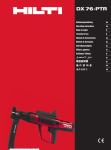
1
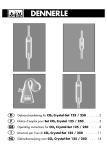
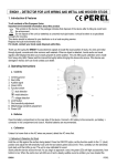
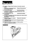
GB Pneumatic Framing Nailer
F
Cloueuse pneumatique sur cadre
NL Pneumatische nagelaandrijver
AN942
Instruction Manual
Manuel d’instructions
Gebruiksaanwijzing
)
.3
(5
0.
4
53
0.8
3(
0.6 8.3)
4(6
.4)
(CFM)
)
.4
3
4
4(
4
0.
1
2
2
1
0
10
20 30
40
50
2
1
3
3
4
5
6
4
5
7
9
8
6
2
7
10
8
9
11
12
13
10
14
11
15 16
12
13
17
18
19
20
14
15
3
1
21
25
22
26
23
24
16
17
18
19
20
21
27
28
22
4
23
1617
29
24
25
30
31
32
26
27
28
5
Symbols
The followings show the symbols used for the tool. Be sure that you understand their meaning before use.
Symboles
Nous donnons ci-dessous les symboles utilisés pour l’outil. Assurez-vous que vous en avez bien compris la signification avant d’utiliser l’outil.
Symbolen
Voor dit gereedschap worden de volgende symbolen gebruikt. Zorg ervoor dat u de betekenis van deze symbolen
begrijpt alvorens het gereedschap te gebruiken.
❏ Read instruction manual.
❏ Lire le mode d’emploi.
❏ Lees de gebruiksaanwijzing.
❏ Wear safety glasses.
❏ Porter des lunettes de protection.
❏ Draag een veiligheidsbril.
6
ENGLISH
Explanation of general view
1
Compressor air output per
minute
2 Nailing frequency (times/min.)
3 Pneumatic tool oil
4 Holder
5 Nose adapter
6 Magazine
7 Contact arm
8 Nose adapter
9 Adjuster
10 Pusher
11
12
13
14
15
16
17
18
19
20
21
Pusher lever
Depress
Return
Nail stopper
Air socket
Air fitting
Continuos nailing
Intermittent nailing
Change lever
Trigger lock
Hammer
SPECIFICATIONS
Model
AN942
Air pressure .................. 0.44 – 0.83 Mpa (4.4 – 8.3 bar)
Nail Iength ..............................................50 mm – 90 mm
Nail capacity ................................................ 60 – 84 pcs.
Dimensions (L x H x W) .... 446 mm x 376 mm x 108 mm
Min. hose diameter .............................................. 8.5 mm
Net weight ..............................................................3.8 kg
• Due to our continuing program of research and development, the specifications herein are subject to change
without notice.
• Note: Specifications may differ from country to country.
Power supply
The tool should be connected only to a power supply of
the same voltage as indicated on the nameplate, and can
only be operated on single-phase AC supply. They are
double-insulated in accordance with European Standard
and can, therefore, also be used from sockets without
earth wire.
Safety hints
For your own safety, please refer to the enclosed safety
instructions.
IMPORTANT SAFETY INSTRUCTIONS
ENB067-1
WARNING:
WHEN USING THIS TOOL, BASIC SAFETY
PRECAUTIONS SHOULD ALWAYS BE FOLLOWED TO
REDUCE THE RISK OF PERSONAL INJURY,
INCLUDING THE FOLLOWING:
READ ALL INSTRUCTIONS.
• For personal safety and proper operation and maintenance of the tool, read this instruction manual
before using the tool.
• Always wear safety glasses to protect your eyes
from dust or nail injury.
WARNING:
It is an employer’s responsibility to enforce the use of
safety eye protection equipment by the tool operators
and by other persons in the immediate working area.
• Wear hearing protection to protect your ears
against exhaust noise and head protection. Also
wear light but not loose clothing. Sleeves should
be buttoned or rolled up. No necktie should be
worn.
22
23
24
25
26
27
28
29
30
31
32
Small rod
Ejection port
Driver
Pliers
Slot
Change lever
Trigger lock
Drain cock
Air filter
Oiler
Pneumatic oil
• Rushing the job or forcing the tool is dangerous.
Handle the tool carefully. Do not operate when
under the influence of alcohol, drugs or the like.
General Tool Handling Guidelines:
1. Always assume that the tool contains fasteners.
2. Do not point the tool toward yourself or anyone
whether it contains fasteners or not.
3. Do not activate the tool unless the tool is placed
firmly against the workpiece.
4. Respect the tool as a working implement.
5. No horseplay.
6. Do not hold or carry the tool with a finger on the
trigger.
7. Do not load the tool with fasteners when any one
of the operating controls is activated.
8. Do not operate the tool with any power source
other than that specified in the tool operating/
safety instructions.
• An improperly functioning tool must not be used.
• Sparks sometimes fly when the tool is used. Do not
use the tool near volatile, flammable materials such
as gasoline, thinner, paint, gas, adhesives, etc.;
they will ignite and explode, causing serious injury.
• The area should be sufficiently illuminated to
assure safe operations. The area should be clear
and litter-free. Be especially careful to maintain
good footing and balance.
• Only those involved in the work should be in the
vicinity. Children especially must be kept away at
all times.
• There may be local regulations concerning noise
which must be complied with by keeping noise levels within prescribed limits. In certain cases, shutters should be used to contain noise.
• Do not play with the contact element: it prevents
accidental discharge, so it must be kept on and not
removed. Securing the trigger in the ON position is
also very dangerous. Never attempt to fasten the
trigger. Do not operate a tool if any portion of the
tool operating controls is inoperable, disconnected, altered, or not working properly.
• Operate the tool within the specified air pressure of
0.44 – 0.83 MPa (4.4 – 8.3 bar) for safety and longer
tool life. Do not exceed the recommended max.
operating pressure of 0.83 MPa (8.3 bar). The tool
should not be connected to a source whose pressure potentially exceeds 1.37 MPa (13.7 bar).
7
• Make sure that the pressure supplied by the compressed air system does not exceed the maximum
allowable pressure of the fastener driving tool. Set
the air pressure initially to the lower value of the
recommended allowable pressure (see SPECIFICATIONS).
• Never use the tool with other than compressed air.
If bottled gas (carbon dioxide, oxygen, nitrogen,
hydrogen, air, etc.) or combustible gas (hydrogen,
propane, acetylene, etc.) is used as a power source
for this tool, the tool will explode and cause serious
injury.
• Always check the tool for its overall condition and
loose screws before operation. Tighten as
required.
• Make sure all safety systems are in working order
before operation. The tool must not operate if only
the trigger is pulled or if only the contact arm is
pressed against the wood. It must work only when
both actions are performed. Test for possible faulty
operation with nails unloaded and the pusher in
fully pulled position.
• Make sure that the trigger is locked when the
change lever is set to the LOCK position.
• Check walls, ceilings, floors, roofing and the like
carefully to avoid possible electrical shock, gas
leakage, explosions, etc. caused by striking live
wires, conduits or gas pipes.
• Use only nails specified in this manual.
• The use of any other nails may cause malfunction
of the tool.
• Never use fastener driving tools marked
with the symbol “Do not use on scaffoldings, ladders” for specific application for example:
- when changing one driving location to another
involves the use of scaffoldings, stairs, ladders,
or ladder alike constructions, e.g. roof laths;
- closing boxes or crates;
- fitting transportation safety systems e.g. on vehicles and wagons.
• Do not permit those uninstructed to use the tool.
• Make sure no one is nearby before nailing. Never
attempt to nail from both the inside and outside at
the same time. Nails may rip through and/or fly off,
presenting a grave danger.
• Watch your footing and maintain your balance with
the tool. Make sure there is no one below when
working in high locations, and secure the air hose
to prevent danger if there is sudden jerking or
catching.
• On rooftops and other high locations, nail as you
move forward. It is easy to lose your footing if you
nail while inching backward. When nailing against
perpendicular surface, nail from the top to the bottom. You can perform nailing operations with less
fatigue by doing so.
• A nail will be bent or the tool can become jammed if
you mistakenly nail on top of another nail or strike
a knot in the wood. The nail may be thrown and hit
someone, or the tool itself can react dangerously.
Place the nails with care.
8
• Do not leave the loaded tool or the air compressor
under pressure for a long time out in the sun. Be
sure that dust, sand, chips and foreign matter will
not enter the tool in the place where you leave it
setting.
• Do not point the ejection port at anyone in the
vicinity. Keep hands and feet away from the ejection port area.
• When the air hose is connected, do not carry the
tool with your finger on the trigger or hand it to
someone in this condition. Accidental firing can be
extremely dangerous.
• Handle the tool carefully, as there is high pressure
inside the tool that can be dangerous if a crack is
caused by rough handling (dropping or striking).
Do not attempt to carve or engrave on the tool.
• Stop nailing operations immediately if you notice
something wrong or out of the ordinary with the
tool.
• Always disconnect the air hose and remove all of
the nails:
1. When unattended.
2. Before performing any maintenance or repair.
3. Before cleaning a jam.
4. Before moving the tool to a new location.
• Perform cleaning and maintenance right after finishing the job. Keep the tool in tip-top condition.
Lubricate moving parts to prevent rusting and minimize friction-related wear. Wipe off all dust from
the parts.
• When not operating the tool, always lock the trigger
by turning the change lever to the LOCK position.
• Do not operate this tool if it does not contain a legible WARNING LABEL.
• Do not modify tool without authorization from
Makita.
• Ask Makita’s Authorized service centers for periodical inspection of the tool.
• To maintain product SAFETY and RELIABILITY,
maintenance and repairs should be performed by
Makita Authorized Service Centers, always using
Makita replacement parts.
SAVE THESE INSTRUCTIONS.
INSTALLATION
Selecting compressor (Fig. 1)
Select a compressor that has ample pressure and air
output to assure cost-efficient operation. The graph
shows the relation between nailing frequency, applicable
pressure and compressor air output. Thus, for example, if
nailing takes place at a rate of approximately 40 times
per minute at a compression of 0.59 MPa (5.9 bar), a
compressor with an air output over 3 CFM (ft3/minute) is
required. Pressure regulators must be used to limit air
pressure to the rated pressure of the tool where air supply pressure exceeds the tool’s rated pressure. Failure to
do so may result in serious injury to tool operator or persons in the vicinity.
Selecting air hose (Fig. 2)
Use an air hose as large and as short as possible to
assure continuous, efficient nailing operation. With an air
pressure of 0.49 MPa (4.9 bar), an air hose with an internal diameter of over 8.5 mm (5/16") and a length of less
than 20 m (6.6 ft.) is recommended when the interval
between each nailing is 0.5 seconds. Air supply hoses
shall have a minimum working pressure rating of
1.03 MPa (10.3 bar) or 150 percent of the maximum
pressure produced in the system whichever is higher.
CAUTION:
• Low air output of the compressor, or a long or smaller
diameter air hose in relation to the nailing frequency
may cause a decrease in the driving capability of the
tool.
Lubrication (Fig. 3 & 4)
To insure maximum performance, install an air set (oiler,
regulator, air filter) as close as possible to the tool. Adjust
the oiler so that one drop of oil will be provided for every
30 nails.
When an air set is not used, oil the tool with pneumatic
tool oil by placing 2 (two) or 3 (three) drops into the air fitting. This should be done before and after use. For
proper lubrication, the tool must be fired a couple of
times after pneumatic tool oil is introduced.
FUNCTIONAL DESCRIPTION
Nose adapter (Fig. 5 & 6)
CAUTION:
• Always lock the trigger and disconnect the hose before
installing or removing the nose adapter.
When nailing workpieces with easily-marred surfaces,
use the nose adapter. It is stored in the holder on the
reverse side of the magazine.
Attach the nose adapter to the contact arm. When not in
use, store the nose adapter in the holder on the reverse
side of the magazine to keep it from being lost.
Adjusting depth of nailing (Fig. 7)
CAUTION:
• Always lock the trigger and disconnect the hose before
adjusting the depth of nailing.
To adjust the depth of nailing, turn the adjuster so that
the arrow above the adjuster will point to the number indicated on the adjuster. The depth of nailing is the deepest
when the arrow points to the number 1. It will become
shallower as the arrow points to higher number. The
depth can be changed in approx. 1.0 mm increments per
graduation. If nails cannot be driven deep enough even
when the arrow points to the number 1, increase the air
pressure. If nails are driven too deep even when the
arrow points to the number 9, decrease the air pressure.
Generally speaking, the tool service life will be longer
when the tool is used with lower air pressure and the
adjuster set to a lower number.
ASSEMBLY
Loading nailer (Fig. 8 & 9)
CAUTION:
• Always lock the trigger and disconnect the hose before
loading the nailer.
Select nails suitable for your work. Insert strip of nails
into the magazine.
Pull the pusher lever to the rear to engage the pusher to
the last nail.
Unloading nailer (Fig. 10 & 11)
CAUTION:
• Always disconnect the air hose before unloading the
nailer.
Pull the pusher lever to the rear. Return the pusher lever
back while keeping the pusher depressed to disengage it
from the strip of nails.
Depress the nail stopper and remove the strip of nails
from the magazine.
Connecting air hose (Fig. 12)
Lock the trigger. Slip the air socket of the air hose onto
the air fitting on the nailer. Be sure that the air socket
locks firmly into position when installed onto the air fitting. A hose coupling must be installed on or near the tool
in such a way that the pressure reservoir will discharge at
the time the air supply coupling is disconnected.
OPERATION
CAUTION:
• Make sure all safety systems are in working order
before operation.
1.
2.
To drive a nail, you may place the contact element
against the workpiece and pull the trigger (Fig. 13),
or
Pull the trigger first and then place the contact element against the workpiece. (Fig. 14)
However when the tool is set to the “Intermittent Nailing”
mode, WITH THE TRIGGER HELD IN A HALF-PULLED
POSITION, an unexpected nailing could occur, if the contact element is allowed to re-contact against the workpiece or the other surface under the influence of recoil.
In order to avoid this unexpected nailing, perform as follows;
1. Do not place the contact element against the workpiece with excessive force.
2. Pull the trigger fully and hold it on for 1 – 2 seconds
after nailing.
No. 1 method is for intermittent nailing, when you wish to
drive a nail carefully and very accurately.
No. 2 method is for continuous nailing.
For No. 1 method, set the change lever to the “Intermittent Nailing” position. For No. 2 method, set the change
lever to the “Continuous Nailing” position. Before using
the change lever to change the nailing method, always
make sure that the change lever is properly set to the
position for the desired nailing method. (Fig. 15)
Anti dry fire mechanism
This tool is equipped with an anti dry fire mechanism.
When there are a few nails remaining in the magazine,
the contact arm will be locked in the undepressed position to prevent the tool from being activated. Load more
nails to resume operation.
9
Jammed nailer (Fig. 16 & 17)
CAUTION:
• Always lock the trigger, disconnect the hose and
remove the nails from the magazine before cleaning a
jam.
When the nailer becomes jammed, do as follows:
Insert a small rod or the like into the ejection port and tap
it with a hammer to retract the driver. Use pliers to bend
the jammed nail so that the nail head comes out of the
slot in the driver guide. Then remove the jammed nail.
Nails (Fig. 18 & 19)
Handle nail strips and their box carefully. If the nail strips
have been handled roughly, they may be out of shape or
their connector breaks, causing poor nail feed.
Avoid storing nails in a very humid or hot place or place
exposed to direct sunlight.
Noise and Vibration
ENG006-1
The typical A-weighted noise levels are
sound pressure level: 89 dB (A)
sound power level: 102 dB (A)
– Wear ear protection. –
The typical weighted root mean square acceleration
value is 4 m/s2.
EC-DECLARATION OF CONFORMITY
We declare under our sole responsibility that this product is
in compliance with the following standards of standardized
documents, EN792 in accordance with Council Directives,
98/37/EC.
Yasuhiko Kanzaki
CE 2003
MAINTENANCE
CAUTION:
• Always disconnect the hose before attempting to perform inspection or maintenance.
Maintenance of nailer
Always check the tool for its overall condition and loose
screws before operation. Tighten as required. (Fig. 20)
With tool disconnected, make daily inspection to assure
free movement of the contact element and trigger. Do not
use tool if the contact element or trigger sticks or binds.
(Fig. 21)
Make sure that the trigger is locked when the change
lever is set to the LOCK position. (Fig. 22)
When the tool is not to be used for an extended period of
time, lubricate the tool using pneumatic tool oil and store
the tool in a safe place. Avoid exposure to direct sunlight
and/or humid or hot environment. (Fig. 23 & 24)
Maintenance of compressor, air set and air hose
After operation, always drain the compressor tank and
the air filter. If moisture is allowed to enter the tool, It may
result in poor performance and possible tool failure.
(Fig. 25 & 26)
Check regularly to see if there is sufficient pneumatic oil
in the oiler of the air set. Failure to maintain sufficient
lubrication will cause O-rings to wear quickly. (Fig. 27)
Keep the air hose away from heat (over 60°C, over
140°F), away from chemicals (thinner, strong acids or
alkalis). Also, route the hose away from obstacles which
it may become dangerously caught on during operation.
Hoses must also be directed away from sharp edges and
areas which may lead to damage or abrasion to the hose.
(Fig. 28)
To maintain product SAFETY and RELIABILITY, repairs,
any other maintenance or adjustment should be performed by Makita Authorized Service Centers, always
using Makita replacement parts.
10
Director
MAKITA INTERNATIONAL EUROPE LTD.
Michigan Drive, Tongwell, Milton Keynes,
Bucks MK15 8JD, ENGLAND
FRANÇAIS
Descriptif
1
Sortie d’air du compresseur par
minute
2 Fréquence de clouage (clous/
min)
3 Huile pour outil pneumatique
4 Support
5 Adaptateur de bec
6 Magasin
7 Bras de contact
8 Adaptateur de bec
9 Dispositif de réglage
10 Pousseur
11
12
13
14
15
16
17
18
19
20
21
22
Levier du pousseur
Appuyer
Rabattre
Butée à clou
Douille à air
Raccord à air
Clouage continu
Clouage intermittent
Levier de changement de mode
Verrou de la gâchette
Marteau
Petite tige métallique
SPÉCIFICATIONS
Modèle
AN942
Pression d’air ................ 0,44 – 0,83 Mpa (4,4 – 8,3 bar)
Longueur de clou....................................50 mm – 90 mm
Capacité de clouage .................................... 60 – 84 pcs.
Dimensions (L x H x P) ..... 446 mm x 376 mm x 108 mm
Diamètre minimal du tuyau .................................. 8,5 mm
Poids net ................................................................3,8 kg
• Etant donné l’évolution constante de notre programme
de recherche et de développement, les spécifications
contenues dans ce manuel sont sujettes à modification
sans préavis.
• Note : Les spécifications peuvent varier suivant les
pays.
Alimentation
L’outil ne devra être raccordé qu’à une alimentation de la
même tension que celle qui figure sur la plaque signalétique, et il ne pourra fonctionner que sur un courant secteur monophasé. Réalisé avec une double isolation, il est
conforme à la réglementation européenne et peut de ce
fait être alimenté sans mise à la terre.
Consignes de sécurité
Pour votre propre sécurité, reportez-vous aux consignes
de sécurité qui accompagnent l’outil.
CONSIGNES DE SÉCURITÉ IMPORTANTES
MISE EN GARDE :
PAR MESURE DE SÉCURITÉ, DES PRÉCAUTIONS
DE BASE DOIVENT ÊTRE PRISES LORS DE
L’UTILISATION DE CET OUTIL, AFIN DE RÉDUIRE
LES RISQUES DE BLESSURE. CES MESURES
COMPRENNENT LES SUIVANTES :
LISEZ TOUTES LES INSTRUCTIONS.
• Par mesure de sécurité personnelle et pour assurer
une utilisation et un entretien adéquat, veuillez lire
ce manuel d’instructions avant d’utiliser l’outil.
• Portez toujours des lunettes de sécurité pour protéger vos yeux contre toute blessure au contact de
la poussière ou d’un clou.
MISE EN GARDE :
L’employeur a la responsabilité d’imposer le port d’un dispositif de protection des yeux aux utilisateurs des outils
et à toute personne présente dans l’aire de travail.
23
24
25
26
27
28
29
30
31
32
Orifice d’éjection
Dispositif d’entraînement
Pince
Fente
Levier de changement de mode
Verrou de la gâchette
Robinet de vidange
Filtre à air
Réservoir d’huile
Huile à outil pneumatique
• Portez une protection d’oreilles pour les protéger
contre le bruit, et portez un casque de sécurité. Les
vêtements portés doivent être légers et ne doivent
pas être amples. Veuillez boutonner ou rouler vos
manches. Ne portez pas de cravate.
• Il est dangereux de travailler trop vite ou d’appliquer une charge de travail excessive à l’outil. Manipulez l’outil avec soin. N’utilisez pas l’outil si vous
avez consommé de l’alcool, des médicaments, etc.
Conseils généraux pour l’utilisation des outils :
1. Gardez toujours à l’esprit que l’outil contient des
clous.
2. L’outil ne doit jamais être pointé vers vous-même
ou vers une autre personne, qu’il contienne ou
non des clous.
3. Ne mettez pas l’outil en marche avant qu’il ne
soit fermement placé sur la pièce à travailler.
4. Respectez votre outil en tant qu’instrument de
travail.
5. Évitez tout chahut.
6. L’outil ne doit jamais être saisi ou transporté en
posant un doigt sur la gâchette.
7. Ne mettez jamais de clous dans l’outil alors que
l’une de ses commandes est activée.
8. Ne branchez jamais l’outil sur une source d’alimentation autre que celle spécifiée dans les instructions d’utilisation et consignes de sécurité
qui l’accompagnent.
• Tout outil défectueux ne doit pas être utilisé.
• Des étincelles s’échappent parfois de l’outil pendant son utilisation. N’utilisez pas l’outil près de
substances ou matériaux volatiles ou inflammables
tels que l’essence, le diluant, la peinture, le gaz, les
adhésifs, etc. Ils risqueraient de prendre feu,
d’exploser et de causer une blessure grave.
• L’aire de travail doit être suffisamment éclairée
pour assurer la sécurité du travail. L’aire de travail
doit être maintenue propre et exempte de déchets.
Prenez particulièrement soin de maintenir une
bonne prise au sol et une bonne position d’équilibre.
• Seules les personnes qui participent au travail doivent pénétrer dans l’aire de travail. Les enfants,
tout particulièrement, doivent être maintenus à
l’écart en tout temps.
11
• Il se peut que des réglementations locales s’appliquent concernant les niveaux de bruit permis.
Veuillez les respecter. Le cas échéant, des volets
doivent être installés pour réduire le bruit.
• Ne modifiez pas l’élément de contact. Il permet de
prévenir toute décharge accidentelle et doit donc
être laissé en place. Il est également très dangereux de fixer la gâchette en position de marche. Il
ne faut jamais essayer d’immobiliser la gâchette.
N’utilisez jamais un outil dont une des commandes
est inutilisable, déconnectée, modifiée ou ne fonctionne pas correctement.
• Par mesure de précaution et pour augmenter la
durée de vie de l’outil, réglez-le toujours à l’intérieur de la plage de pression d’air spécifiée, de 0,44
à 0,83 MPa (4,4 à 8,3 bar). Ne dépassez jamais la
pression maximale recommandée de 0,83 MPa
(8,3 bar). L’outil ne doit pas être raccordé à une
source dont la pression peut dépasser 1,37 MPa
(13,7 bar).
• Assurez-vous que la pression fournie par le système d’air comprimé ne dépasse pas la pression
maximale permise de la cloueuse. Réglez d’abord
la pression d’air sur la plus petite valeur de pression recommandée (voir SPÉCIFICATIONS).
• Cet outil doit être exclusivement utilisé avec de l’air
comprimé. L’utilisation d’une bouteille de gaz
(dioxyde de carbone, oxygène, nitrogène, hydrogène, air, etc.) ou de gaz combustible (hydrogène,
propane, acétylène, etc.) comme source de pression de cet outil entraînera une explosion et risque
de causer une blessure grave.
• Avant d’utiliser l’outil, assurez-vous qu’il est en
bon état et qu’aucune de ses vis n’est desserrée.
Le cas échéant, serrez les vis.
• Assurez-vous que tous les dispositifs de sécurité
sont en état de fonctionner avant d’utiliser l’outil.
En principe cet outil ne fonctionne pas si vous
appuyez seulement sur la gâchette ou si vous
appuyez simplement le bras de contact contre le
bois. Il est nécessaire que ces deux actions soient
exécutées pour que l’outil fonctionne. Retirez les
clous de l’outil et tirez le pousseur à fond pour vérifier l’absence de tout vice de fonctionnement.
• Assurez-vous que la gâchette est verrouillée lorsque vous réglez le levier de changement de mode
en position LOCK.
• Pour éviter tout risque de choc électrique, de fuite
de gaz, d’explosion, etc., provoqué par le contact
avec des fils dénudés, des conduites ou des tuyaux
de gaz, vérifiez le mur, le plafond, le plancher, le toit
ou toute autre pièce où vous clouez.
• Utilisez uniquement les clous spécifiés dans ce
manuel.
• L’outil risque de mal fonctionner si vous utilisez
tout autre type de clou.
• Il ne faut jamais utiliser les outils de
clouage qui portent l’indication “Do not
use on scaffoldings, ladders” dans des
situations suivantes :
- lorsqu’il faut utiliser un échafaudage, un escalier,
une échelle, etc. ;
- pour poser des clous sur des lattes de toit ;
- pour fermer des boîtes ou des caisses, ou ;
12
•
•
•
•
•
•
•
•
•
•
•
- pour installer des dispositifs de sécurité sur un
véhicule ou un wagon.
Seules les personnes ayant pris connaissance du
fonctionnement de l’outil doivent être autorisées à
l’utiliser.
Avant de procéder au clouage, assurez-vous que
personne ne se trouve près de vous. N’essayez
jamais de clouer une pièce en même temps des
côtés intérieur et extérieur. Cela est très dangereux, puisque les clous risquent alors de défoncer
la pièce ou d’être projetés.
Regardez où vous posez les pieds et assurez-vous
d’un bon équilibre pendant l’utilisation de l’outil.
Assurez-vous qu’il n’y a personne sous vous lorsque vous travaillez dans un endroit élevé, et fixez le
tuyau d’air de sorte qu’il ne risque pas de se détacher s’il est secoué ou s’il se coince.
Sur les toits et autres endroits élevés, clouez en
vous déplaçant vers l’avant. Vous risquez de perdre
pied si vous clouez en vous déplaçant à reculons.
Lorsque vous clouez sur une surface horizontale,
faites-le du haut vers le bas. De cette façon le travail de clouage sera moins exigeant physiquement.
Le clou risque de se plier ou l’outil de se bloquer si
vous clouez par inadvertance dans un nœud ou sur
un autre clou. Le clou risque alors d’être projeté et
de frapper quelqu’un, ou bien l’outil lui-même risque de réagir de manière dangereuse. Choisissez
l’emplacement des clous avec soin.
N’abandonnez pas pour une période prolongée un
outil chargé ou un compresseur d’air sous pression exposé au soleil à l’extérieur. Assurez-vous de
toujours déposer l’outil en un endroit où la poussière, le sable, les copeaux et corps étrangers ne
risquent pas d’y pénétrer.
Ne pointez jamais la sortie d’éjection vers une personne se trouvant à proximité. Gardez les mains et
les pieds à l’écart de la zone de la sortie d’éjection.
Pour transporter l’outil ou le donner à quelqu’un
alors que le tuyau d’air est raccordé, ne posez pas
le doigt sur la gâchette. Le déclenchement accidentel de l’outil peut être extrêmement dangereux.
Manipulez l’outil prudemment. La pression élevée à
l’intérieur de l’outil représente un danger si une fissure est provoquée par un manipulation brusque
(laisser tomber l’outil ou le frapper). Ne tentez
jamais de tailler ou graver une inscription sur
l’outil.
Cessez immédiatement le clouage si vous notez
une anomalie ou un fonctionnement inhabituel de
l’outil.
Déconnectez toujours le tuyau d’air et retirez tous
les clous dans les cas suivants :
1. Lorsque l’outil est abandonné sans surveillance.
2. Avant d’effectuer tout travail d’entretien ou de
réparation sur l’outil.
3. Avant de réparer un blocage.
4. Avant de déplacer l’outil vers un autre lieu.
• Procédez au nettoyage et à l’entretien de l’outil une
fois le travail terminé. Maintenez l’outil en excellente condition. Lubrifiez les pièces mobiles pour
éviter qu’elles ne rouillent et pour limiter l’usure
entraînée par la friction. Retirez toute poussière
déposée sur les pièces.
• Lorsque vous n’utilisez pas l’outil, verrouillez toujours la gâchette en tournant le levier de changement de mode sur la position VERROUILLAGE.
• N’utilisez pas cet outil si aucune ÉTIQUETTE
D’AVERTISSEMENT lisible n’y est apposée.
• Ne modifiez pas l’outil sans l’autorisation de
Makita.
• Confiez régulièrement l’outil à un centre de service
après-vente agréé Makita pour une inspection.
• Pour maintenir la SÉCURITÉ et la FIABILITÉ du produit, son entretien et sa réparation doivent être
effectués dans un centre de service après-vente
agréé Makita, exclusivement avec des pièces de
rechange Makita.
CONSERVEZ CES INSTRUCTIONS.
INSTALLATION
Sélection du compresseur (Fig. 1)
Choisissez un compresseur dont la capacité de pressurisation et de sortie d’air assurera un bon rapport qualité/
coût. Le graphique indique la relation entre la fréquence
de clouage, la pression applicable et la sortie d’air du
compresseur. Ainsi, par exemple, un clouage à raison
d’environ 40 clous par minute avec une pression de
0,59 MPa (5,9 bar) nécessite une sortie d’air supérieure
à 3 pi³/min. Un régulateur de pression doit être utilisé si
la pression d’air fournie dépasse la capacité nominale de
l’outil. Autrement, l’utilisateur et les personnes présentes
courent un risque de blessure grave.
Sélection du tuyau d’air (Fig. 2)
Le tuyau d’air utilisé doit être le plus large et le plus court
possible, pour assurer un travail de clouage continu et
efficace. Avec une pression d’air de 0,49 MPa (4,9 bar),
nous recommandons tuyau d’air d’un diamètre interne
supérieur à 8,5 mm (5/6 po) et d’une longueur inférieure
à 20 m (6,6 pi) pour un intervalle de 0,5 seconde entre
chaque clou. Les tuyaux d’adduction d’air doivent avoir
une pression de service minimale de 1,03 MPa (10,3 bar)
ou de 1,5 fois la pression maximale produite par le système, la valeur la plus élevée parmi les précédentes
s’appliquant.
Lubrification (Fig. 3 et 4)
Pour assurer une performance maximale, installez une
chambre à air (qui contient le réservoir d’huile, le régulateur et le filtre à air) le plus près possible de l’outil. Ajustez le réservoir d’huile de sorte qu’une goutte d’huile soit
fournie à intervalles de 30 clous.
Si vous n’utilisez pas de chambre à air, graissez l’outil en
versant deux (2) ou trois (3) gouttes d’huile pour outil
pneumatique dans le raccord à air. Cette opération doit
être effectuée avant et après l’utilisation. Pour assurer
une lubrification adéquate, il faut faire déclencher l’outil à
quelques reprises après l’insertion de l’huile pour outil
pneumatique.
DESCRIPTION DU FONCTIONNEMENT
Adaptateur de bec (Fig. 5 et 6)
ATTENTION :
• Verrouillez toujours la gâchette et déconnectez le tuyau
avant d’installer ou de retirer l’adaptateur de bec.
Utilisez l’adaptateur de bec pour clouer dans des pièces
dont la surface s’abîme facilement. Il est rangé dans le
support qui se trouve de l’autre côté du magasin.
Fixez l’adaptateur de bec sur le bras de contact. Lorsque
vous n’utilisez pas le bec, rangez-le dans le support qui
se trouve de l’autre côté du magasin, pour éviter de le
perdre.
Réglage de la profondeur de clouage (Fig. 7)
ATTENTION :
• Verrouillez toujours la gâchette et déconnectez le tuyau
avant de régler la profondeur de clouage.
Pour régler la profondeur de clouage, tournez la bague
de réglage de sorte que la flèche qui se trouve au-dessus de la bague pointe sur un des chiffres indiqués sur la
bague. La profondeur de clouage est maximale lorsque
la flèche pointe sur le chiffre 1. Plus la flèche pointe sur
un chiffre élevé, plus la profondeur diminue. La modification de la profondeur s’effectue par pas d’environ
1,0 mm. Si les clous ne s’enfoncent pas assez profondément même lorsque la flèche pointe sur le chiffre 1, augmentez la pression d’air. Si les clous s’enfoncent trop
profondément même lorsque la flèche pointe sur le chiffre 9, réduisez la pression d’air. En général, la durée de
service de l’outil est plus longue s’il est utilisé avec une
faible pression d’air et avec la bague de réglage placée
sur un chiffre peu élevé.
ATTENTION :
• La capacité d’entraînement de l’outil risque de diminuer
si la sortie d’air du compresseur est faible ou si le tuyau
d’air est trop long ou d’un diamètre trop petit pour la
fréquence de clouage.
13
ASSEMBLAGE
Chargement de la cloueuse (Fig. 8 et 9)
ATTENTION :
• Verrouillez toujours la gâchette et déconnectez le tuyau
avant de charger la cloueuse.
Choisissez des clous qui conviennent au type de travail à
effectuer. Insérez une bande de clous dans le magasin.
Tirez le levier du pousseur vers l’arrière pour placer le
pousseur vis-à-vis du dernier clou.
Pour retirer les clous de la cloueuse
(Fig. 10 et 11)
ATTENTION :
• Déconnectez toujours le tuyau à air avant de retirer les
clous de la cloueuse.
Tirez le levier du pousseur vers l’arrière. Remettez le
levier du pousseur en place tout en maintenant enfoncé
le pousseur lui-même pour le retirer de la bande de
clous.
Appuyez sur la butée à clou et retirez la bande de clous
du magasin.
Raccordement du tuyau d’air (Fig. 12)
Verrouillez la gâchette. Glissez la douille à air du tuyau
d’air dans le raccord à air de la cloueuse. Assurez-vous
que la douille à air est verrouillée fermement en position
lorsque vous installez le raccord à air. Un raccord à tuyau
doit être installé sur ou près de l’outil de sorte que le
réservoir de pression se vide au moment de la déconnexion du raccord d’adduction d’air.
UTILISATION
ATTENTION :
• Assurez-vous que tous les dispositifs de sécurité sont
en état de fonctionner avant d’utiliser l’outil.
1.
2.
Pour clouer, vous pouvez placer l’élément de contact
contre la pièce et appuyer sur la gâchette. (Fig 13)
ou
Vous pouvez aussi appuyer d’abord sur la gâchette
puis placer l’élément de contact contre la pièce.
(Fig. 14)
Toutefois, si l’outil est réglé en mode de “clouage intermittent”, avec LA GÂCHETTE MAINTENUE À MICOURSE, vous risquez de clouer par inadvertance si
l’élément de contact touche à nouveau la pièce à travailler ou toute autre surface sous l’effet du recul.
Pour éviter ce clouage accidentel, procédez comme suit :
1. N’appliquez pas une pression excessive lorsque
vous appliquez l’élément de contact contre la pièce
à travailler.
2. Appuyez à fond sur la gâchette et maintenez-la dans
cette position 1 ou 2 secondes après le clouage.
La méthode 1 convient bien au clouage intermittent, lorsque vous désirez enfoncer les clous soigneusement,
avec une grande précision.
La méthode 2 convient bien au clouage continu.
Pour utiliser la méthode 1, réglez le levier de changement de mode sur la position “Clouage intermittent”. Pour
utiliser la méthode 2, réglez le levier de changement de
mode sur la position “Clouage continu”. Avant chaque utilisation, assurez-vous que le levier de changement de
mode est réglé sur la méthode de clouage désirée.
(Fig. 15)
14
Mécanisme de protection contre le clouage à vide
Cet outil est équipé d’un mécanisme qui prévient le
clouage à vide. Lorsqu’il ne reste que quelques clous
dans le magasin, le bras de contact se verrouille en position élevée, pour empêcher l’activation de l’outil. Pour
poursuivre votre travail, vous devez alors insérer d’autres
clous.
Cloueuse bloquée (Fig. 16 et 17)
ATTENTION :
• Avant de débloquer la cloueuse, vous devez toujours
verrouiller la gâchette, déconnecter le tuyau et retirer
les clous du magasin.
Lorsque la cloueuse se bloque, procédez comme suit :
Insérez une petite tige ou un objet similaire dans la sortie
d’éjection et frappez dessus légèrement avec un marteau pour retirer le dispositif d’entraînement. Utilisez une
pince pour plier le clou bloqué de sorte que la tête du
clou sorte de la fente du guide d’entraînement. Retirez
ensuite le clou coincé.
Clous (Fig. 18 et 19)
Manipulez avec soin les bandes de clous et les boîtes de
clous. Si un bande de clous est manipulée de manière
brusque, elle risque d’être déformée ou la connexion
entre les clous risque de se détacher, causant une mauvaise alimentation en clous.
Évitez de ranger les clous dans un endroit très humide
ou chaud, ou dans un endroit exposé directement aux
rayons du soleil.
ENTRETIEN
ATTENTION :
• Déconnectez toujours le tuyau avant d’effectuer tout
travail d’inspection ou d’entretien sur l’outil.
Entretien de la cloueuse
Avant d’utiliser l’outil, assurez-vous qu’il est en bon état
et qu’aucune de ses vis n’est desserrée. Le cas échéant,
serrez les vis. (Fig. 20)
L’outil doit être débranché et inspecté chaque jour pour
s’assurer que l’élément de contact et la gâchette se
déplacent librement. N’utilisez pas l’outil si l’élément de
contact ou la gâchette se bloque ou se coince. (Fig. 21)
Assurez-vous que la gâchette est verrouillée lorsque
vous réglez le levier de changement de mode en position
VERROUILLAGE. (Fig. 22)
Si vous prévoyez que l’outil restera inutilisé pendant une
période prolongée, lubrifiez-le avec de l’huile à outil
pneumatique et rangez-le dans un endroit sûr. Évitez de
l’exposer directement aux rayons du soleil et/ou de le
laisser dans un environnement humide ou chaud.
(Fig. 23 et 24)
Entretien du compresseur, de la chambre à air et
du tuyau d’air
Après l’utilisation, videz toujours le réservoir du compresseur et le filtre à air. L’outil risque de mal fonctionner ou
de tomber en panne si l’humidité y pénètre.
(Fig. 25 et 26)
Vérifiez régulièrement le chambre à air pour vous assurer que le réservoir d’huile contient assez d’huile à outil
pneumatique. Les joints toriques s’useront rapidement
s’ils ne sont pas toujours bien graissés. (Fig. 27)
Gardez le tuyau d’air à l’écart de la chaleur (plus de 60°C
ou 140°F) et des produits chimiques (diluant, acides
puissants, substances alcalines). Il faut également faire
courir le tuyau à l’écart des obstacles où il risquerait de
se coincer pendant l’utilisation de l’outil. Les tuyaux doivent également être placés à l’écart des bords tranchants et de toute surface pouvant entraîner
l’endommagement ou l’abrasion du tuyau. (Fig. 28)
Pour maintenir la SÉCURITÉ et la FIABILITÉ du produit,
les réparations, l’inspection et le remplacement des charbons, et tout autre travail d’entretien ou de réglage doivent être effectués dans un centre de service Makita
agréé ou un centre de service de l’usine Makita, exclusivement avec des pièces de rechange Makita.
Bruit et vibrations
ENG006-1
Les niveaux de bruit pondérés A types sont:
niveau de pression sonore: 89 dB (A)
niveau de puissance du son: 102 dB (A)
– Porter des protecteurs anti-bruit. –
L’accélération pondérée est de 4 m/s2.
DÉCLARATION DE CONFORMITÉ CE
Nous déclarons sous notre entière responsabilité que ce
produit est conforme aux normes des documents standardisés suivants, EN792 conformément aux Directives
du Conseil, 98/37/EC.
Yasuhiko Kanzaki
CE 2003
Director
MAKITA INTERNATIONAL EUROPE LTD.
Michigan Drive, Tongwell, Milton Keynes,
Bucks MK15 8JD, ENGLAND
15
NEDERLANDS
Verklaring van algemene gegevens
1
Compressor luchtopbrengst per
minuut
2 Aandrijffrequentie (keer/minuut)
3 Olie voor pneumatisch gereedschap
4 Houder
5 Neusadapter
6 Magazijn
7 Contactarm
8 Neusadapter
9 Stelring
10 Stoter
11
12
13
14
15
16
17
18
19
20
21
22
Stoterhendel
Indrukken
Terugbrengen
Nagelstopper
Mof
Luchtinlaat
Continu nagelen
Intermitterend nagelen
Keuzehendel
Trekkervergrendeling
Hamer
Dunne staaf
TECHNISCHE GEGEVENS
Model
AN942
Luchtdruk ......................0,44 – 0,83 Mpa (4,4 – 8,3 bar)
Nagellengte ............................................50 mm – 90 mm
Capaciteit nagelmagazijn ............................... 60 – 84 st.
Afmetingen (L x H x B) ......446 mm x 376 mm x 108 mm
Min. diameter slang ............................................. 8,5 mm
Netto gewicht ......................................................... 3,8 kg
• In verband met ononderbroken research en ontwikkeling behouden wij ons het recht voor bovenstaande
technische gegevens te wijzigen zonder voorafgaande
kennisgeving.
• Opmerking: De technische gegevens kunnen van land
tot land verschillen.
Stroomvoorziening
Het gereedschap mag alleen worden aangesloten op
een stroombron van hetzelfde voltage als aangegeven op
de naamplaat, en kan alleen op enkel-fase wisselstroom
worden gebruikt. Het gereedschap is dubbel-geïsoleerd
volgens de Europese standaard en kan derhalve ook op
een niet-geaard stopcontact worden aangesloten.
Veiligheidswenken
Voor uw veiligheid dient u de bijgevoegde Veiligheidsvoorschriften nauwkeurig op te volgen.
BELANGRIJKE
VEILIGHEIDSVOORSCHRIFTEN
WAARSCHUWING:
BIJ HET GEBRUIK VAN DIT GEREEDSCHAP DIENEN
DE BASISVEILIGHEIDSMAATREGELEN, INCLUSIEF
DE ONDERSTAANDE MAATREGELEN, ALTIJD TE
WORDEN OPGEVOLGD OM HET GEVAAR VOOR
PERSOONLIJKE VERWONDING TE BEPERKEN:
LEES ALLE VOORSCHRIFTEN.
• Om uw persoonlijke veiligheid en een correcte
bediening en onderhoud van het gereedschap te
verzekeren, dient u deze gebruiksaanwijzing te
lezen voordat u het gereedschap in gebruik neemt.
• Draag altijd een veiligheidsbril om uw ogen te
beschermen tegen stof en mogelijke verwonding
door nagels.
16
23
24
25
26
27
28
29
30
31
32
Uitwerpopening
Aandrijving
Tang
Sleuf
Keuzehendel
Trekkervergrendeling
Aftapkraan
Luchtfilter
Oliespuit
Pneumatische olie
WAARSCHUWING:
Het is de verantwoordelijkheid van de werkgever erop toe
te zien dat de gebruikers van het gereedschap en andere
personen die zich dicht bij de werkplek bevinden altijd
oogbescherming dragen.
• Draag hoofdbescherming en ook oorbescherming
om uw gehoor te beschermen tegen het uitlaatgeluid. Draag lichte, nauwsluitende kleding. Mouwen
dienen dichtgeknoopt of opgerold te worden. De
gebruiker van het gereedschap mag geen das dragen.
• Overhaast te werk gaan of het gereedschap forceren is gevaarlijk. Hanteer het gereedschap voorzichtig. Gebruik het gereedschap niet onder
invloed van alcohol, drugs en dergelijke.
Algemene richtlijnen voor het hanteren van het
gereedschap:
1. Neem altijd aan dat er nagels in het gereedschap
zijn geplaatst.
2. Richt het gereedschap nooit op uzelf of op anderen, ongeacht of er nagels in het gereedschap
zijn geladen of niet.
3. Activeer het gereedschap niet tenzij het stevig
tegen het werkstuk is geplaatst.
4. Hanteer het gereedschap altijd als een werktuig.
5. Ravot nooit met het gereedschap.
6. Houd of draag het gereedschap nooit met uw
vinger op de trekker.
7. Laad nooit nagels in het gereedschap terwijl een
van de bedieningsschakelaars geactiveerd is.
8. Gebruik het gereedschap niet op een andere
krachtbron behalve de krachtbron die in de
gebruiksvoorschriften/veiligheidsvoorschriften
is opgegeven.
• Een slecht werkend gereedschap mag niet worden
gebruikt.
• Tijdens het gebruik van het gereedschap worden er
soms vonken voortgebracht. Gebruik het gereedschap daarom niet in de nabijheid van vluchtige,
ontvlambare materialen zoals benzine, verdunner,
verf, gas, lijmstoffen, enz. Deze materialen zouden
kunnen ontbranden of ontploffen en ernstige verwondingen veroorzaken.
• Werk altijd in een goed verlichte ruimte om een veilig gebruik te verzekeren. Houd de werkomgeving
schoon en vrij van rommel. Let vooral goed op dat
u stevige steun voor de voeten hebt en uw evenwicht behoudt.
• Alleen personen die direct bij het werk betrokken
zijn mogen in de werkomgeving komen. Vooral kinderen dienen altijd uit de buurt te worden gehouden.
• Alle plaatselijke wetten betreffende de geluidshinder dienen te worden nageleefd door het geluidsniveau
van
het
gereedschap
binnen
de
voorgeschreven limieten te houden. In bepaalde
gevallen dienen luiken te worden gebruikt om de
geluidshinder te beperken.
• Knoei niet met het contactelement. Dit element
voorkomt het toevallig afladen van het gereedschap en dient daarom steeds op zijn plaats te zijn
aangebracht. De trekker vastzetten in de AAN positie is ook uiterst gevaarlijk. Probeer nooit om de
trekker vast te zetten. Gebruik het gereedschap
niet indien een van de schakelaars niet werkt, niet
goed is aangesloten, gewijzigd werd, of niet goed
functioneert.
• Gebruik het gereedschap binnen de voorgeschreven luchtdruk van 0,44 – 0,83 MPa (4,4 – 8,3 bar) om
een veilige werking en een langere levensduur te
verzekeren. Overschrijd de aanbevolen maximale
druk van 0,83 MPa (8,3 bar) niet. Het gereedschap
mag niet worden aangesloten op een bron die een
druk voortbrengt van mogelijk meer dan 1,37 Mpa
(13,7 bar).
• Zorg dat de druk die door het luchtdruksysteem
wordt voortgebracht niet hoger is dan de maximaal
toelaatbare druk van het nagelaandrijfgereedschap. Stel de luchtdruk aanvankelijk in op de minimumwaarde van de aanbevolen toelaatbare druk
(zie TECHNISCHE GEGEVENS).
• Gebruik uitsluitend samengeperste lucht als de
krachtbron voor het gereedschap. Indien gas in
flessen (kooldioxide, zuurstof, stikstof, waterstof,
lucht, e.d.) of brandbaar gas (waterstof, propaan,
acetyleen, e.d.) als de krachtbron voor dit gereedschap wordt gebruikt, zal het gereedschap ontploffen en ernstige verwonding veroorzaken.
• Controleer vóór het gebruik altijd of het gereedschap in goede staat is en alle schroeven stevig
zijn aangedraaid. Trek de schroeven zonodig aan.
• Controleer vóór het gebruik altijd of alle veiligheidsinrichtingen normaal functioneren. Het
gereedschap mag niet werken indien enkel de trekker wordt ingedrukt of enkel de contactarm tegen
het hout wordt gedrukt. Het gereedschap mag
alleen werken indien beide handelingen achtereen
worden uitgevoerd. Controleer op mogelijk foutieve
werking zonder dat er nagels zijn geladen en met
de stoter in de volledig ingetrokken positie.
• Controleer of de trekker vergrendelt wanneer de
keuzehendel op “LOCK” wordt gezet.
• Controleer muren, plafonds, dakbalken e.d. zorgvuldig op eventueel aanwezige elektrische bedrading, leidingbuizen of gasleidingen, om het gevaar
voor elektrische schok, gaslekkage, explosies e.d.
te voorkomen.
• Gebruik uitsluitend de nagels die in deze gebruiksaanwijzing zijn gespecificeerd.
• Het gebruik van andere soorten nagels kan defect
van het gereedschap als gevolg hebben.
• Nagelaandrijfgereedschap dat voorzien
is van de waarschuwing “Niet gebruiken op stellingen, ladders, enz.” mag
nooit worden gebruikt voor specifieke
werkzaamheden zoals de volgende:
- gebruikmaken van stellingen, een trap, een ladder, of een structuur zoals daklatten, om nagels
op verschillende plaatsen in te drijven;
- houten kisten of kratten dichtnagelen;
- transportveiligheidssystemen e.d. vastzetten op
een voertuig of vrachtwagen.
• Sta niet toe dat onbevoegden het gereedschap
gebruiken.
• Controleer of er zich niemand in de buurt bevindt
alvorens te nagelen. Probeer nooit om nagels vanaf
zowel de binnenzijde als de buitenzijde in te drijven. De nagels kunnen het werkstuk openrijten en/
of eruit schieten, hetgeen bijzonder gevaarlijk is.
• Let op uw stappen en behoud uw evenwicht wanneer u het gereedschap gebruikt. Controleer of er
zich niemand beneden u bevindt wanneer u op
hoge plaatsen gaat werken, en klem de luchtslang
stevig vast om gevaarlijke situaties, veroorzaakt
door een plotselinge ruk aan de slang of het blijven
haken ervan, te voorkomen.
• Wanneer u op daken of andere hooggelegen plaatsen werkt, dient u te nagelen terwijl u voorwaarts
beweegt. Als u nagelt terwijl u achterwaarts
beweegt, kunt u gemakkelijk uw evenwicht verliezen. Wanneer u nagelt in een loodrecht oppervlak,
dient u te nagelen vanaf de bovenkant naar de
onderkant. Het werk is dan minder vermoeiend.
• Als u per ongeluk een nagel vlak op een andere
nagel aandrijft of met het gereedschap op een
knoest in het hout stoot, zal de nagel krommen en
kan het gereedschap vastlopen. De nagel kan ook
weggeslingerd worden en iemand raken, of het
gereedschap kan gevaarlijk terugslaan. Wees
daarom voorzichtig bij het kiezen van de plaatsen
waar u nagelt.
• Laat het geladen gereedschap of de op druk
gezette luchtcompressor niet voor lange tijd in de
zon liggen. Laat het gereedschap niet achter op
een plaats waar stof, zand, spanen en verontreinigingen erin terecht kunnen komen.
• Richt de uitwerpopening van het gereedschap niet
op personen in de nabijheid. Houd uw handen en
voeten uit de buurt van de uitwerpopening.
• Wanneer de luchtslang is aangesloten, mag u het
gereedschap niet met uw vinger op de trekker dragen of het in deze staat aan iemand anders overhandigen.
Toevallige
ontlading
van
het
gereedschap kan uiterst gevaarlijk zijn.
• Behandel het gereedschap voorzichtig. De hoge
druk in het gereedschap kan gevaar opleveren
indien er scheuren in het gereedschap komen ten
gevolge van ruwe behandeling (het gereedschap
laten vallen of tegen iets aanstoten). Kerf of graveer niets op het gereedschap.
17
• Stop onmiddellijk met nagelen wanneer u vaststelt
dat het gereedschap niet goed of abnormaal werkt.
• Maak altijd de luchtslang los en haal alle nagels uit
het gereedschap:
1. Wanneer u het gereedschap alleen achterlaat.
2. Alvorens te beginnen met onderhoud of reparatie.
3. Alvorens een vastgelopen gereedschap vrij te
maken.
4. Alvorens het gereedschap naar een andere
plaats te brengen.
• Telkens nadat het werk is voltooid, dient u het
gereedschap schoon te maken en te onderhouden.
Houd het gereedschap in tiptop-conditie. Smeer de
bewegende onderdelen om roesten te voorkomen
en de slijtage door wrijving tot een minimum te
beperken. Veeg alle stof op de onderdelen van het
gereedschap eraf.
• Wanneer u het gereedschap niet gebruikt, dient u
altijd de trekker te vergrendelen door de keuzehendel op “LOCK” te zetten.
• Gebruik het gereedschap niet indien het niet voorzien is van een leesbaar WARNING LABEL.
• Wijzig het gereedschap niet zonder de toestemming van Makita.
• Laat de periodieke inspectie van het gereedschap
uitvoeren door een erkend Makita servicecentrum.
• Om de VEILIGHEID en BETROUWBAARHEID van
het gereedschap te handhaven, dienen alle onderhoud en reparaties te worden uitgevoerd door een
erkend Makita servicecentrum, en altijd met
gebruikmaking van Makita vervangingsonderdelen.
BEWAAR DEZE VOORSCHRIFTEN.
INSTALLEREN
Kiezen van de compressor (Fig. 1)
Kies een compressor die ruimschoots voldoende druk en
luchtopbrengst levert om een rendabele werking te verzekeren. De grafiek toont de verhouding tussen de aandrijffrequentie,
de
toepasselijke
druk
en
de
luchtopbrengst van de compressor. Bij voorbeeld, indien
u nagelt met een frequentie van ongeveer 40 keer per
minuut bij een druk van 0,59 MPa (5,9 bar), is een compressor met een luchtopbrengst van 3 CFM (ft3/minuut)
vereist. Wanneer de aangevoerde luchtdruk de nominale
druk van het gereedschap overschrijdt, dienen drukregelaars te worden gebruikt om de luchtdruk te verlagen tot
de nominale druk. Als u dit niet doet, bestaat er gevaar
voor ernstige verwonding van de gebruiker van het
gereedschap of andere personen in de nabijheid.
18
Kiezen van de luchtslang (Fig. 2)
Gebruik een zo breed mogelijke en zo kort mogelijke
luchtslang om een continue en effectieve aandrijving te
verzekeren. Bij een luchtdruk van 0,49 MPa (4,9 bar), is
het aan te bevelen een luchtslang te gebruiken met een
binnendiameter van meer dan 8,5 mm en een lengte van
minder dan 20 m wanneer het interval tussen de aandrijfbeurten 0,5 seconde bedraagt. Luchtslangen dienen een
minimale werkdruk te hebben van 1,03 MPa (10,3 bar) of
150 percent van de maximale druk die in het systeem
wordt voortgebracht, welke van beide waarden de hoogste is.
LET OP:
• Een lage luchtopbrengst van de compressor, een te
lange luchtslang, of een luchtslang met een kleinere
diameter in verhouding tot de aandrijffrequentie, kunnen leiden tot een verminderd aandrijfvermogen van
het gereedschap.
Smering (Fig. 3 en 4)
Om optimale prestaties te krijgen dient een luchtset (oliespuit, regulateur, luchtfilter) zo dicht mogelijk bij het
gereedschap te worden geïnstalleerd. Stel de oliespuit
zodanig af dat één druppel olie voor iedere 30 nagels zal
worden ingespoten.
Wanneer u geen luchtset gebruikt, dient u het gereedschap te smeren met olie voor pneumatisch gereedschap door 2 (twee) of 3 (drie) druppels olie in de
luchtinlaat aan te brengen. Doe dit zowel vóór als na het
gebruik. Om een goede smering te verzekeren dient u
het gereedschap na het aanbrengen van de olie een
paar keer af te laden.
BESCHRIJVING VAN DE FUNCTIES
Neusadapter (Fig. 5 en 6)
LET OP:
• Vergrendel altijd de trekker en maak de slang los alvorens de neusadapter te installeren of te verwijderen.
Gebruik de neusadapter om te nagelen in werkstukken
met oppervlakken die gemakkelijk bederven. De neusadapter is opgeborgen in de houder op de achterzijde
van het magazijn.
Bevestig de neusadapter aan de contactarm. Wanneer u
de neusadapter niet gebruikt, dient u hem op te bergen in
de houder op de achterzijde van het magazijn zodat u
hem niet kwijtraakt.
Instellen van de aandrijfdiepte (Fig. 7)
LET OP:
• Vergrendel altijd de trekker en maak de slang los alvorens de aandrijfdiepte in te stellen.
Om de aandrijfdiepte in te stellen, draait u de stelring
zodat het pijltje boven de stelring wijst naar het gewenste
cijfer op de stelring. De aandrijfdiepte is het grootst wanneer het pijltje wijst naar het cijfer 1. De diepte vermindert naarmate het pijltje naar een hoger cijfer wijst. De
diepte verandert ongeveer 1,0 mm voor elke schaalverdeling. Vermeerder de luchtdruk indien de nagels niet
diep genoeg ingedreven worden ook wanneer het pijltje
naar het cijfer 1 wijst. Verminder de luchtdruk indien de
nagels te diep ingedreven worden wanneer het pijltje
naar het cijfer 9 wijst. Doorgaans zal het gereedschap
langer meegaan als het wordt gebruikt met lagere luchtdruk en met de stelring ingesteld op een lager cijfer.
INEENZETTEN
Laden van het nagelmagazijn (Fig. 8 en 9)
LET OP:
• Vergrendel altijd de trekker en maak de slang los alvorens het nagelmagazijn te laden.
Kies nagels die geschikt zijn voor uw werk. Breng een
strip nagels in het magazijn.
Trek de stoterhendel naar achteren zodat de stoter tegen
de laatste nagel komt te zitten.
Leegmaken van het nagelmagazijn (Fig. 10 en 11)
LET OP:
• Maak de slang los alvorens het nagelmagazijn leeg te
maken.
Trek de stoterhendel naar achteren. Breng de stoterhendel terug terwijl u de stoter ingedrukt houdt zodat hij vrijkomt van de nagelstrip.
Druk de nagelstopper in en haal de nagelstrip uit het
magazijn.
Aansluiten van de luchtslang (Fig. 12)
Mechanisme ter voorkoming van ‘leeg vuren’
Dit gereedschap is voorzien van een mechanisme om
‘leeg vuren’ te voorkomen. Wanneer er slechts weinig
nagels in het magazijn overblijven, zal de contactarm in
de niet-ingedrukte positie vergrendeld blijven om te voorkomen dat het gereedschap wordt aangedreven. Om verder te kunnen werken dient u meer nagels in het
magazijn te laden.
Vastgelopen nagels verwijderen (Fig. 16 en 17)
LET OP:
• Vergrendel altijd de trekker, maak de slang los en haal
de nagels uit het magazijn alvorens een vastgelopen
nagel te verwijderen.
Ga als volgt te werk indien een nagel in de aandrijving is
vastgelopen:
Steek een dunne staaf of iets dergelijks in de uitwerpopening en tik erop met een hamer om de aandrijving
terug te trekken. Gebruik een tang om de vastgelopen
nagel te buigen zodat de nagelkop uit de sleuf in de
geleider van de aandrijving te voorschijn komt. Verwijder
daarna de vastgelopen nagel.
Vergrendel de trekker. Monteer de mof van de luchtslang
op de luchtinlaat van het gereedschap. Zorg dat de mof
stevig vastzit op de luchtinlaat van het gereedschap. Een
slangkoppeling dient op of dicht bij het gereedschap te
worden geïnstalleerd zodat de druktank zal ontlast worden wanneer de luchttoevoerkoppeling wordt losgemaakt.
Nagels (Fig. 18 en 19)
BEDIENING
ONDERHOUD
LET OP:
• Controleer vóór het gebruik of alle veiligheidsinrichtingen goed werken.
LET OP:
• Maak altijd de slang los alvorens te beginnen met
inspectie of onderhoud van het gereedschap.
1.
2.
Om een nagel aan te drijven, plaats het contactelement tegen het werkstuk en druk de trekker in
(Fig. 13), of
Druk eerst de trekker in en plaats daarna het contact
element tegen het werkstuk. (Fig. 14)
Wanneer het gereedschap echter ingesteld is op
“Intermitterend nagelen” en DE TREKSCHAKELAAR IN
EEN
HALF-INGEDRUKTE
POSITIE
WORDT
GEHOUDEN, kan onverwacht nagelen optreden indien
het contactelement het werkstuk opnieuw raakt of een
ander oppervlak raakt ten gevolge van terugslag.
Ga als volgt te werk om dit soort onverwacht nagelen te
voorkomen.
1. Oefen niet te veel kracht uit wanneer u het
contactelement tegen het werkstuk plaatst.
2. Druk de trekschakelaar volledig in en houd hem 1 tot
2 seconden ingedrukt nadat de nagel is aangedreven.
Behandel nagelstrips en hun doos voorzichtig. Door ruwe
behandeling kunnen de nagelstrips vervormd raken of
kunnen hun verbindingen breken zodat de nagels niet
goed zullen worden aangevoerd.
Bewaar de nagels niet op zeer vochtige of warme plaatsen en ook niet in direct zonlicht.
Onderhoud van het gereedschap
Controleer vóór het gebruik altijd of het gereedschap in
goede staat is en of alle schroeven stevig zijn aangedraaid. Draai de schroeven zonodig aan. (Fig. 20)
Zorg dat het gereedschap is losgekoppeld en inspecteer
dagelijks of het contactelement en de trekker soepel
bewegen. Gebruik het gereedschap niet indien het contactelement en de trekker stroef bewegen of klemmen.
(Fig. 21)
Controleer of de trekker vergrendelt wanneer de keuzehendel op “LOCK” wordt gezet. (Fig. 22)
Smeer het gereedschap met olie voor pneumatisch
gereedschap en berg het op in een veilige plaats wanneer u het gereedschap voor langere tijd niet gaat
gebruiken. Vermijd blootstelling aan direct zonlicht en/of
een vochtige of warme omgeving. (Fig. 23 en 24)
De 1ste methode is voor intermitterend nagelen wanneer
u de nagels voorzichtig en zeer nauwkeurig wilt aandrijven.
De 2de methode is voor continu nagelen. Voor de 1ste
methode dient u de keuzehendel in te stellen op de positie voor “Intermitterend nagelen”. Voor de 2de methode
dient u de keuzehendel in te stellen op de positie voor
“Continu nagelen”. Na het veranderen van de positie van
de keuzehendel dient u altijd te controleren of de keuzehendel is ingesteld op de positie die overeenkomt met de
gewenste aandrijfmethode. (Fig. 15)
19
Geluidsniveau en trilling
Onderhoud van de compressor, luchtset en
luchtslang
ENG006-1
Tap na het gebruik altijd de compressortank en het luchtfilter af. Als er vocht in het gereedschap terechtkomt,
kunnen de prestaties verslechteren en kan het gereedschap defect raken. (Fig. 25 en 26)
Controleer regelmatig of er voldoende pneumatische olie
in de oliespuit van de luchtset aanwezig is. Als het
gereedschap niet goed gesmeerd blijft, zullen de O-ringen snel verslijten. (Fig. 27)
Houd de luchtslang uit de buurt van hitte (meer dan
60°C) en chemicaliën (verdunner, sterke zuren of alkalis). Houd de slang ook uit de buurt van obstakels waaraan deze tijdens het gebruik zou kunnen blijven haken.
Plaats de slang ook niet dicht bij scherpe randen of
andere plaatsen waar de slang beschadigd of afgeschuurd zou kunnen worden. (Fig. 28)
Om de VEILIGHEID en BETROUWBAARHEID van het
product te handhaven, dienen alle reparaties en alle
andere onderhoudswerkzaamheden of afstellingen te
worden uitgevoerd door een erkend Makita Servicecentrum, en dat uitsluitend met gebruik van Makita vervangingsonderdelen.
De typische A-gewogen geluidsniveau’s zijn
geluidsdrukniveau: 89 dB (A)
geluidsenergie-niveau: 102 dB (A)
– Draag oorbeschermers. –
De typische gewogen effectieve versnellingswaarde is
4 m/s2.
EG-VERKLARING VAN CONFORMITEIT
Wij verklaren hierbij uitsluitend op eigen verantwoordelijkheid dat dit produkt voldoet aan de volgende
normen van genormaliseerde documenten, EN792 in
overeenstemming met de richtlijnen van de Raad 98/73/
EC.
Yasuhiko Kanzaki
CE 2003
Director
MAKITA INTERNATIONAL EUROPE LTD.
Michigan Drive, Tongwell, Milton Keynes,
Bucks MK15 8JD, ENGLAND
Makita Corporation
884238A988


![Stiftnagler SK 335- 201 C deutsch [1] Abmessungen:L = 254](http://vs1.manualzilla.com/store/data/006281873_1-8c943fec4e20e2e88c178e3bef799b9c-150x150.png)