1
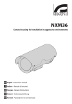
NXM36
Housing for installation in aggressive environments
EN English - Instructions manual
IT Italiano - Manuale di istruzioni
FR Français - Manuel d’instructions
DE Deutsch - Bedienungslanleitung
NXM36
Housing for installation in aggressive environments
EN English - Instructions manual
Contents
ENGLISH
1 About this manual.......................................................................................................... 3
1.1 Typographical conventions................................................................................................................................... 3
2 Notes on copyright and information on trademarks................................................... 3
3 Safety rules..................................................................................................................... 3
4 Identification................................................................................................................... 3
4.1 Product description and type designation..................................................................................................... 3
4.2 Product markings..................................................................................................................................................... 3
5 Preparing the product for use....................................................................................... 4
5.1 Unpacking and contents........................................................................................................................................ 4
5.1.1 Unpacking................................................................................................................................................................................... 4
5.1.2 Contents....................................................................................................................................................................................... 4
5.2 Safely disposing of packaging material............................................................................................................ 4
6 Assembling and installing............................................................................................. 4
6.1 Installation................................................................................................................................................................... 4
6.1.1 How to open the housing...................................................................................................................................................... 4
6.1.2 How to install the camera...................................................................................................................................................... 5
6.1.2.1 Version 12Vdc/24Vac.................................................................................................................................................................................... 5
6.1.2.2 Version 115/230Vac....................................................................................................................................................................................... 5
6.1.3 Closing the housing................................................................................................................................................................. 5
6.1.1 Installing the housing............................................................................................................................................................. 6
6.1.1.1 Fixing the sunshield (optional)................................................................................................................................................................. 6
6.1.2 Heating......................................................................................................................................................................................... 7
7 Maintaining and cleaning.............................................................................................. 7
7.1 Window and plastic cover cleaning (PC).......................................................................................................... 7
8 Disposal of waste materials........................................................................................... 7
9 Technical data................................................................................................................. 8
9.1 General......................................................................................................................................................................... 8
9.2 Mechanical.................................................................................................................................................................. 8
9.3 Electrical....................................................................................................................................................................... 8
9.4 Environment............................................................................................................................................................... 8
9.5 Certifications.............................................................................................................................................................. 8
10 Technical drawings....................................................................................................... 9
• The device must be installed only and exclusively
by qualified technical personnel.
Before installing and using this unit, please read this
manual carefully. Be sure to keep it handy for later
reference.
• Before any technical work on the appliance,
disconnect the power supply.
1.1 Typographical conventions
DANGER!
High level hazard.
Risk of electric shock. Disconnect the
power supply before proceeding with any
operation, unless indicated otherwise.
WARNING!
Medium level hazard.
This operation is very important for the
system to function properly. Please read
the procedure described very carefully and
carry it out as instructed.
INFO
Description of system specifications.
We recommend reading this part carefully
in order to understand the subsequent
stages.
2 Notes on copyright and
information on trademarks
The quoted names of products or companies are
trademarks or registered trademarks.
3 Safety rules
The manufacturer declines all responsibility
for any damage caused by an improper use
of the appliances mentioned in this manual.
Furthermore, the manufacturer reserves
the right to modify its contents without any
prior notice. The documentation contained
in this manual has been collected with great
care, the manufacturer, however, cannot
take any liability for its use. The same thing
can be said for any person or company
involved in the creation and production of
this manual.
• Do not use power supply cables that seem worn
or old.
• Never, under any circumstances, make any
changes or connections that are not shown in
this handbook. Improper use of the appliance
can cause serious hazards, risking the safety of
personnel and of the installation.
• Use only original spare parts. Non-original spare
parts could cause fire, electrical discharge or other
hazards.
• Before proceeding with installation check the
supplied material to make sure it corresponds
to the order specification by examining the
identification labels (4.2 Product markings, page 3).
4 Identification
4.1 Product description and type
designation
The NXM36 housing, entirely constructed from AISI
316L electropolished stainless steel, is designed to
operate in special environments such as marine,
industrial, chemical and where the external
conditions are highly corrosive.
The housing has a cylindrical body with a 130mm
(5.1in) diameter, closed by two 6mm thick circular
flanges. There are 2 PG13.5 cable glands for outdoor
connections on the rear flange.
A wide range of accessories for mounting the
equipment is available thereby satisfying all
installation needs.
4.2 Product markings
See the label attached to the product.
3
Instructions manual - English - EN
1 About this manual
EN - English - Instructions manual 5 Preparing the product for
use
Any change that is not expressly approved
by the manufacturer will invalidate the
guarantee.
5.1 Unpacking and contents
5.1.1 Unpacking
6 Assembling and installing
The assembly and installation must be
performed only by skilled personnel.
6.1 Installation
6.1.1 How to open the housing
To open the housing, unscrew the bolts on the rear
flange, using the allen wrench supplied.
When the product is delivered, make sure that the
package is intact and that there are no signs that it
has been dropped or scratched.
If there are obvious signs of damage, contact the
supplier immediately.
Keep the packaging in case you need to send the
product for repairs.
5.1.2 Contents
Check the contents to make sure they correspond
with the list of materials as below:
• Housing
Fig. 1
Slide out the rear cover plate of the housing, taking
care to leave the sealing washer in its seating.
• Housing equipment:
• Allen wrench
• Spacers
• Screws and washers
• Screws for camera
• Instructions manual
5.2 Safely disposing of packaging
material
The packaging material can all be recycled. The
installer technician will be responsible for separating
the material for disposal, and in any case for
compliance with the legislation in force where the
device is to be used.
When returning a faulty product we recommend
using the original packaging for shipping.
4
Fig. 2
6.1.2 How to install the camera
6.1.2.2 Version 115/230Vac
This chapter described how to install the camera into
the housing.
IN 115/230Vac
Instructions manual - English - EN
Open the housing following the instructions given
above. (6.1.1 How to open the housing, page 4).
Fit the camera on the slide, using the insulating plate
and the supplied 1/4” screw. If necessary, use the
spacers to position the camera and optics correctly.
OUT 115/230Vac
Heater OUT 115/230Vac
Fig. 5
6.1.3 Closing the housing
Fig. 3
Feed the cables through the cable grip, and make the
necessary electrical connections, ensuring that the
cable grips are holding firmly.
6.1.2.1 Version 12Vdc/24Vac
When the power supply voltage is 24Vac the circuit
will be connected by the terminals shown.
Before closing the housing reinsert the bottom
orientating the slide according to the installation
required, on the wall bracket or on the Pan & tilt
head, for the right camera fitting. (6.1.1 Installing the
housing, page 6).
Close the housing taking care not to damage the
sealing ring. Make sure that the sealing ring is
correctly fitted in its position.
Pay attention to the fixing. Tightening
torque: 4Nm max.
IN 12Vdc/24Vac
OUT 12Vdc/24Vac
Heater OUT 12Vdc/24Vac
Fig. 4
5
EN - English - Instructions manual 6.1.1 Installing the housing
6.1.1.1 Fixing the sunshield (optional)
This section describes how to install the housing on
the wall bracket or on the Pan & Tilt head.
Screw the equipped exagonal spacers on the flanges
of the housing (01). Position the sunshield on the
housing (02) and fix it on the spacers with the
equipped screws (03).
Before closing the housing, be sure to have rightly
fitted the internal slide according to the type of
installation.
02
03
01
Fig. 8
Fig. 6
Wall installation.
Fig. 7
P&T installation.
6
6.1.2 Heating
7 Maintaining and cleaning
7.1 Window and plastic cover
cleaning (PC)
Surface dirt should be rinsed away with water and
then the window cleaned with a neutral soap diluted
with water, or specific products for spectacle lens
cleaning. These should be applied with a soft cloth.
Avoid ethyl alcohol, solvents, hydrogenated
hydrocarbide, strong acid and alkali. Such
products may irreparably damage the
surface.
Fig. 9
8 Disposal of waste
materials
This symbol mark and recycle system
are applied only to EU countries and not
applied to the countries in the other area of
the world.
Fig. 10
Your product is designed and manufactured with
high quality materials and components which can be
recycled and reused.
This symbol means that electrical and electronic
equipment, at their end-of-life, should be disposed of
separately from your household waste.
Please dispose of this equipment at your local
Community waste collection or Recycling centre.
In the European Union there are separate collection
systems for used electrical and electronic products.
7
Instructions manual - English - EN
Some models of housing are equipped with heater
and double heater.
EN - English - Instructions manual 9 Technical data
9.3 Electrical
9.1 General
Heating (Ton 15°C±3°C (59°F ±5°F), Toff 22°C±3°C
(77°F±5°F))
Constructed from electropolished stainless steel
(austenitic alloy stainless steel, corrosion and heat
resistant according to the following standards):
-- AISI 316L
-- UNI 6900-71: X 2 Cr Ni Mo 17 12 2
-- Power supply/Consumption: IN 115/230Vac, 40W
max,80W max (with double heater)
Camera power supply
-- DIN 17006: X 2 Cr Ni Mo 17 13 2
-- IN 100-240Vac - OUT 12Vdc, 50/60Hz, 1A
-- N° werkstoff 1.4404
-- IN 230Vac - OUT 24Vac, 50/60Hz, 400mA
-- AFNOR: Z2 CND 17-12
-- BSI: 316S11
The screws utilised are in austenitic alloy stainless
steel, corrosion and heat resistant according to the
following standards:
-- ISO: 7380
-- AISI: 316
-- ISO quality: A4
-- Resistance class ISO: from 50 to 70
UNI: Ente Nazionale Italiano di Unificazione, AISI: American Iron
and Standard Institute, DIN: Deutsche Industrie Normen, AFNOR:
Association Française de Normalisation, BSI: British Standard
Institution, ISO: International Organization for Standardization.
9.2 Mechanical
Cable glands: 2xPG13.5 (nickel-plated brass for
external connections)
Flange thickness: 6mm (0.2in) (front/back)
External body polishing
Gaskets: High sealing O-ring
Tempered window glass
-- Dimensions (Ø): 112mm (4.4in) (external), 97mm
(3.8in) (usable diameter)
-- Thick: 4mm (0.2in)
External dimensions (ØxL): 154x358mm (6.1x14.1in)
Internal usable area (WxH): 88x86mm (3.5x3.4in)
Internal usable area (with double heater) (WxH):
55x100mm (2.2x3.9in)
Internal usable length (without accessories): 334mm
(13.1in)
Internal usable length (with heater and/or power
supply): 245mm (9.6in)
Unit weight: 5kg/11lb
8
-- Power supply/Consumption: IN 12Vdc/24Vac, 20W
max
9.4 Environment
Indoor/Outdoor
Submersible: up to -40m (-130ft) (4Bar pressure)
Operating temperature (with heater): -20°C
(-4°F)/+60°C (140°F)
Operating temperature (with double heater): -40°C
(-40°F)/+60°C (140°F)
9.5 Certifications
CE EN61000-6-3, EN60065, EN50130-4
IP66/IP68 EN60529 IP66/IPx8 (4Bar, for 48 hours)
10 Technical drawings
Instructions manual - English - EN
The dimensions of the drawings are in millimetres.
POWER SUPPLY
164
Ø 154
245
A
USABLE AREA
A-A
A
Ø 112
184
342
346
BOARD
88
460
86
B
USABLE
AREA
B
B-B
358
93
Fig. 11NXM36.
9
Headquarters Italy Videotec S.p.A.
UK Representative office
Via Friuli, 6 - I-36015 - Schio (VI) Italy
Tel. +39 0445 697411 - Fax +39 0445 697414
Email: [email protected]
Tel./Fax +44 01353 775438 (Sales)
Tel. +44 0113 815 0047 (Technical support)
Tel. +44 0113 815 0031 (Orders/Shipping dept.)
Email: [email protected]
France Videotec France S.à.r.l.
Asia Pacific Videotec (HK) Ltd
Voie du Futur, Zac des Portes - 27100 - Val-de-Reuil, France
Tel. +33 2 32094900 - Fax +33 2 32094901
Email: [email protected]
Unit C 24 Floor - Gold King Industrial Building
35-41, Tai Lin Pai Road - Kwai Chung, NT, Hong Kong
Tel. +852 2333 0601 - Fax +852 2311 0026
Email: [email protected]
Americas Videotec Security, Inc.
35 Gateway Drive, Suite 100 - Plattsburgh, NY 12901 - U.S.A.
Tel. +1 518 8250020 - Fax +1 425 648 4289
Email: [email protected] - www.videotec.us
www.videotec.com
MNVCNXM36_1323_EN
NXM36
Custodia per installazioni in ambienti aggressivi
IT Italiano - Manuale di istruzioni
Sommario
ITALIANO
1 Informazioni sul presente manuale.............................................................................. 3
1.1 Convenzioni tipografiche...................................................................................................................................... 3
2 Note sul copyright e informazioni sui marchi commerciali......................................... 3
3 Norme di sicurezza......................................................................................................... 3
4 Identificazione................................................................................................................ 3
4.1 Descrizione e designazione del prodotto........................................................................................................ 3
4.2 Marcatura del prodotto.......................................................................................................................................... 3
5 Preparazione del prodotto per l'utilizzo....................................................................... 4
5.1 Disimballaggio e contenuto................................................................................................................................. 4
5.1.1 Disimballaggio........................................................................................................................................................................... 4
5.1.2 Contenuto................................................................................................................................................................................... 4
5.2 Smaltimento in sicurezza dei materiali di imballaggio............................................................................... 4
6 Assemblaggio e installazione........................................................................................ 4
6.1 Installazione................................................................................................................................................................ 4
6.1.1 Apertura della custodia.......................................................................................................................................................... 4
6.1.2 Installazione della telecamera............................................................................................................................................. 5
6.1.2.1 Versione 12Vdc/24Vac.................................................................................................................................................................................. 5
6.1.2.2 Versione 115/230Vac.................................................................................................................................................................................... 5
6.1.3 Chiusura della custodia.......................................................................................................................................................... 5
6.1.1 Installazione della custodia................................................................................................................................................... 6
6.1.1.1 Fissaggio del tettuccio (opzionale)......................................................................................................................................................... 6
6.1.2 Riscaldamento........................................................................................................................................................................... 7
7 Manutenzione e pulizia.................................................................................................. 7
7.1 Pulizia del vetro e delle parti in plastica (PC).................................................................................................. 7
8 Smaltimento dei rifiuti................................................................................................... 7
9 Dati tecnici...................................................................................................................... 8
9.1 Generale....................................................................................................................................................................... 8
9.2 Meccanica.................................................................................................................................................................... 8
9.3 Elettrico........................................................................................................................................................................ 8
9.4 Ambiente..................................................................................................................................................................... 8
9.5 Certificazioni............................................................................................................................................................... 8
10 Disegni tecnici.............................................................................................................. 9
1 Informazioni sul presente
manuale
1.1 Convenzioni tipografiche
PERICOLO!
Pericolosità elevata.
Rischio di scosse elettriche. Prima di
eseguire qualsiasi operazione assicurarsi di
togliere tensione al prodotto, salvo diversa
indicazione.
ATTENZIONE!
Pericolosità media.
L'operazione è molto importante per il
corretto funzionamento del sistema. Si
prega di leggere attentamente la procedura
indicata e di eseguirla secondo le modalità
previste.
INFO
Descrizione delle caratteristiche del
sistema.
Si consiglia di leggere attentamente per
comprendere le fasi successive.
2 Note sul copyright e
informazioni sui marchi
commerciali
• Prima di effettuare interventi tecnici
sull'apparecchio togliere l'alimentazione elettrica.
• Non utilizzare cavi di alimentazione con segni di
usura o invecchiamento.
• Non effettuare per nessun motivo alterazioni o
collegamenti non previsti in questo manuale.
L'uso di apparecchi non idonei può portare a
gravi pericoli per la sicurezza del personale e
dell'impianto.
• Utilizzare solo parti di ricambio originali. Pezzi di
ricambio non originali potrebbero causare incendi,
scariche elettriche o altri pericoli.
• Prima di procedere con l'installazione controllare
che il materiale fornito corrisponda alle specifiche
richieste esaminando le etichette di marcatura (4.2
Marcatura del prodotto, pagina 3).
4 Identificazione
4.1 Descrizione e designazione
del prodotto
La custodia NXM36, interamente costruita in acciaio
Inox brillantato AISI 316L, è stata progettata per
applicazioni speciali come quella marina, industriale,
chimica o in ambienti dove gli agenti esterni sono
particolarmente corrosivi.
La custodia ha un corpo cilindrico di diametro
130mm chiuso da due flange circolari di 6mm di
spessore. Sulla flangia posteriore sono presenti 2
pressacavi PG13.5 per le connessioni esterne.
I nomi di prodotto o di aziende citati sono marchi
commerciali o marchi commerciali registrati
appartenenti alle rispettive società.
É disponibile un’ampia gamma di accessori di
montaggio che permette di soddisfare qualsiasi
esigenza di installazione.
3 Norme di sicurezza
4.2 Marcatura del prodotto
Il produttore declina ogni responsabilità
per eventuali danni derivanti da un
uso improprio delle apparecchiature
menzionate in questo manuale. Si
riserva inoltre il diritto di modificarne il
contenuto senza preavviso. Ogni cura è
stata posta nella raccolta e nella verifica
della documentazione contenuta in questo
manuale, tuttavia il produttore non può
assumersi alcuna responsabilità derivante
dall'utilizzo della stessa. Lo stesso dicasi
per ogni persona o società coinvolta nella
creazione e nella produzione di questo
manuale.
Vedere l’etichetta posta sul prodotto.
3
Manuale di istruzioni - Italiano - IT
Prima di installare e utilizzare questa unità, leggere
attentamente questo manuale. Conservare questo
manuale a portata di mano come riferimento futuro.
• L'installazione e la manutenzione del dispositivo
deve essere eseguita solo da personale tecnico
qualificato.
IT - Italiano - Manuale di istruzioni 5 Preparazione del
prodotto per l'utilizzo
Qualsiasi cambiamento non espressamente
approvato dal costruttore fa decadere la
garanzia.
5.1 Disimballaggio e contenuto
5.1.1 Disimballaggio
Alla consegna del prodotto verificare che l'imballo
sia integro e non abbia segni evidenti di cadute o
abrasioni.
6 Assemblaggio e
installazione
L'assemblaggio e l'installazione vanno
eseguiti solo da personale qualificato.
6.1 Installazione
6.1.1 Apertura della custodia
Per aprire la custodia svitare le viti poste sulla
flangia posteriore utilizzando la chiave esagonale in
dotazione.
In caso di evidenti segni di danno all'imballo
contattare immediatamente il fornitore.
Conservare l'imballo nel caso sia necessario inviare il
prodotto in riparazione.
5.1.2 Contenuto
Controllare che il contenuto sia corrispondente alla
lista del materiale sotto elencata:
• Custodia
• Dotazione per custodia:
• Chiave a brugola
Fig. 1
Sfilare il fondo della custodia prestando attenzione
che la guarnizione rimanga in sede.
• Distanziali
• Viti e rondelle
• Viti per telecamera
• Manuale di istruzioni
5.2 Smaltimento in sicurezza dei
materiali di imballaggio
I materiali d'imballo sono costituiti interamente da
materiale riciclabile. Sarà cura del tecnico installatore
smaltirli secondo le modalità di raccolta differenziata
o comunque secondo le norme vigenti nel Paese di
utilizzo.
In caso di restituzione del prodotto
malfunzionamente è consigliato l'utilizzo
dell'imballaggio originale per il trasporto.
4
Fig. 2
6.1.2 Installazione della telecamera
6.1.2.2 Versione 115/230Vac
Questa sezione descrive come installare la telecamera
all’interno della custodia.
IN 115/230Vac
Manuale di istruzioni - Italiano - IT
Aprire la custodia come da istruzioni descritte
precedentemente. (6.1.1 Apertura della custodia,
pagina 4).
Montare la telecamera sulla slitta utilizzando la
piastrina isolante e la vite da 1/4” in dotazione. Se
necessario utilizzare i distanziali per posizionare nel
modo corretto telecamera ed ottica.
OUT 115/230Vac
Heater OUT 115/230Vac
Fig. 5
6.1.3 Chiusura della custodia
Fig. 3
Inserire i cavi attraverso i pressacavi ed eseguire le
connessioni elettriche necessarie, assicurarsi che i
pressacavi siano fissati saldamente.
6.1.2.1 Versione 12Vdc/24Vac
Il circuito risulterà connesso tramite i morsetti
indicati nel caso di tensione di alimentazione del
riscaldamento di 24Vac.
Prima di richiudere la custodia reinserire il
fondo orientando la slitta in funzione del tipo
di installazione, su staffa a parete oppure su
brandeggio in modo che la telecamera risulti
posizionata correttamente. (6.1.1 Installazione della
custodia, pagina 6).
Chiudere la custodia prestando attenzione a non
danneggiare la guarnizione di tenuta. Assicurarsi che
la guarnizione sia correttamente inserita nella propria
sede.
Prestare attenzione durante il fissaggio.
Coppia di serraggio: 4Nm max.
IN 12Vdc/24Vac
OUT 12Vdc/24Vac
Heater OUT 12Vdc/24Vac
Fig. 4
5
IT - Italiano - Manuale di istruzioni 6.1.1 Installazione della custodia
6.1.1.1 Fissaggio del tettuccio (opzionale)
Questa sezione descrive come installare la custodia
su staffa a parete o su brandeggio.
Avvitare alle flange della custodia i distanziali
esagonali in dotazione (01). Posizionare il tettuccio
sulla custodia (02) e fissarlo con le viti in dotazione in
corrispondenza dei distanziali (03).
Prima della chiusura, assicurarsi di aver orientato
correttamente la slitta interna della custodia in
funzione del tipo di installazione.
02
03
01
Fig. 8
Fig. 6
Installazione a parete.
Fig. 7
Installazione su brandeggio.
6
6.1.2 Riscaldamento
Alcuni modelli della custodia sono dotati di
riscaldamento normale e doppio.
7 Manutenzione e pulizia
7.1 Pulizia del vetro e delle parti
in plastica (PC)
Manuale di istruzioni - Italiano - IT
Si consigliano saponi neutri diluiti con acqua o
prodotti specifici per la pulizia delle lenti degli
occhiali con l’utilizzo di un panno morbido.
Evitare alcool etilico, solventi, idrocarburi
idrogenati, acidi forti e alcali. L’utilizzo
di detti prodotti danneggia in modo
irreparabile la superficie trattata.
Fig. 9
8 Smaltimento dei rifiuti
Questo simbolo e il sistema di riciclaggio
sono validi solo nei paesi dell'EU e non
trovano applicazione in altri paesi del
mondo.
Il vostro prodotto è costruito con materiali e
componenti di alta qualità, che sono riutilizzabili o
riciclabili.
Fig. 10
Prodotti elettrici ed elettronici che portano questo
simbolo alla fine dell'uso devono essere smaltiti
separatamente dai rifiuti casalinghi.
Vi preghiamo di smaltire questo apparecchio in un
Centro di raccolta o in un'Ecostazione.
Nell'Unione Europea esistono sistemi di raccolta
differenziata per prodotti elettrici ed elettronici.
7
IT - Italiano - Manuale di istruzioni 9 Dati tecnici
9.3 Elettrico
9.1 Generale
Riscaldamento (Ton 15°C±3°C, Toff 22°C±3°C)
Costruita in acciaio inox brillantato (acciaio legato
austenitico inossidabile resistente alla corrosione e
al calore):
-- AISI 316L
-- Alimentazione/Consumo: IN 115/230Vac, 40W
max,80W max (con doppio riscaldamento)
Alimentatore per telecamera
-- UNI 6900-71: X 2 Cr Ni Mo 17 12 2
-- IN 100-240Vac - OUT 12Vdc, 50/60Hz, 1A
-- DIN 17006: X 2 Cr Ni Mo 17 13 2
-- IN 230Vac - OUT 24Vac, 50/60Hz, 400mA
-- N° werkstoff 1.4404
-- AFNOR: Z2 CND 17-12
9.4 Ambiente
-- BSI: 316S11
Interno/Esterno
La viteria impiegata è realizzata in acciaio legato
austenitico inossidabile resistente alla corrosione e
al calore:
-- ISO: 7380
-- AISI: 316
-- Qualità ISO: A4
-- Classe di resistenza ISO: da 50 a 70
UNI: Ente Nazionale Italiano di Unificazione, AISI: American Iron
and Standard Institute, DIN: Deutsche Industrie Normen, AFNOR:
Association Française de Normalisation, BSI: British Standard
Institution, ISO: International Organization for Standardization.
9.2 Meccanica
Pressacavi: 2xPG13.5 (ottone nichelato per le
connessioni esterne)
Spessore della flangia: 6mm (anteriore/posteriore)
Brillantatura esterna corpo
Guarnizioni: O-ring a tenuta elevata
Finestra in vetro temperato
-- Dimensioni (Ø): 112mm (esterno), 97mm
(diametro utile)
-- Spessore: 4mm
Dimensioni esterne (ØxL): 154x358mm
Dimensioni utili interne (WxH): 88x86mm
Dimensioni utili interne (con doppio riscaldamento)
(WxH): 55x100mm
Lunghezza utile interna (senza accessori): 334mm
Lunghezza utile interna (con riscaldamento e/o
alimentatore): 245mm
Peso unitario: 5kg
8
-- Alimentazione/Consumo: IN 12Vdc/24Vac, 20W
max
Sommersione: fino a -40m (pressione 4Bar)
Temperatura di esercizio (con riscaldamento): -20°C
/+60°C
Temperatura di esercizio (con doppio riscaldamento):
-40°C/+60°C
9.5 Certificazioni
CE EN61000-6-3, EN60065, EN50130-4
IP66/IP68 EN60529 IP66/IPx8 (4Bar, per 48 ore)
10 Disegni tecnici
Le dimensioni dei disegni sono espresse in millimetri.
Manuale di istruzioni - Italiano - IT
ALIMENTATORE
164
Ø 154
245
A
AREA UTILE
A-A
A
Ø 112
184
342
346
SCHEDA
88
460
86
B
AREA
UTILE
B
B-B
358
93
Fig. 11NXM36.
9
Headquarters Italy Videotec S.p.A.
UK Representative office
Via Friuli, 6 - I-36015 - Schio (VI) Italy
Tel. +39 0445 697411 - Fax +39 0445 697414
Email: [email protected]
Tel./Fax +44 01353 775438 (Sales)
Tel. +44 0113 815 0047 (Technical support)
Tel. +44 0113 815 0031 (Orders/Shipping dept.)
Email: [email protected]
France Videotec France S.à.r.l.
Asia Pacific Videotec (HK) Ltd
Voie du Futur, Zac des Portes - 27100 - Val-de-Reuil, France
Tel. +33 2 32094900 - Fax +33 2 32094901
Email: [email protected]
Unit C 24 Floor - Gold King Industrial Building
35-41, Tai Lin Pai Road - Kwai Chung, NT, Hong Kong
Tel. +852 2333 0601 - Fax +852 2311 0026
Email: [email protected]
Americas Videotec Security, Inc.
35 Gateway Drive, Suite 100 - Plattsburgh, NY 12901 - U.S.A.
Tel. +1 518 8250020 - Fax +1 425 648 4289
Email: [email protected] - www.videotec.us
www.videotec.com
MNVCNXM36_1323_IT
NXM36
Caisson pour environnements agressifs
FR Français - Manuel d’instructions
Sommaire
FRANÇAIS
1 À propos de ce mode d’emploi...................................................................................... 3
1.1 Conventions typographiques.............................................................................................................................. 3
2 Notes sur le copyright et informations sur les marques de commerce...................... 3
3 Normes de securité......................................................................................................... 3
4 Identification................................................................................................................... 3
4.1 Description et désignation du produit............................................................................................................. 3
4.2 Marquage du produit.............................................................................................................................................. 3
5 Préparation du produit en vue de l’utilisation............................................................. 4
5.1 Déballage et contenu.............................................................................................................................................. 4
5.1.1 Déballage.................................................................................................................................................................................... 4
5.1.2 Contenu....................................................................................................................................................................................... 4
5.2 Élimination sans danger des matériaux d’emballage.................................................................................. 4
6 Assemblage et installation............................................................................................ 4
6.1 Installation................................................................................................................................................................... 4
6.1.1 Ouverture du caisson.............................................................................................................................................................. 4
6.1.2 Installation de la camera........................................................................................................................................................ 5
6.1.2.1 Version 12Vdc/24Vac.................................................................................................................................................................................... 5
6.1.2.2 Version 115/230Vac....................................................................................................................................................................................... 5
6.1.3 Fermeture du caisson.............................................................................................................................................................. 5
6.1.1 Installation du caisson............................................................................................................................................................ 6
6.1.1.1 Fixation du double toit (en option)......................................................................................................................................................... 6
6.1.2 Chauffage.................................................................................................................................................................................... 7
7 Entretien et nettoyage................................................................................................... 7
7.1 Entretiens de la vitre et des parties en plastique (PC)................................................................................. 7
8 Élimination des déchets................................................................................................. 7
9 Données techniques....................................................................................................... 8
9.1 Généralités.................................................................................................................................................................. 8
9.2 Mécanique................................................................................................................................................................... 8
9.3 Électrique..................................................................................................................................................................... 8
9.4 Environnement.......................................................................................................................................................... 8
9.5 Certifications.............................................................................................................................................................. 8
10 Dessins techniques....................................................................................................... 9
1 À propos de ce mode
d’emploi
• L’installation et l’entretien du dispositif doivent
être exclusivement être effectués par un personnel
technique qualifié.
Avant d’installer et d’utiliser cet appareil, veuillez
lire attentivement ce mode d’emploi. Conservez-le à
portée de main pour pouvoir vous y reporter en cas
de besoin.
• Ne pas utiliser de câbles d’alimentation usés ou
endommagés.
DANGER!
Risque élevé.
Risque de choc électrique. Sauf indication
contraire, sectionner l'alimentation avant
de procéder à toute opération.
• Ne procéder sous aucun prétexte à des
modifications ou des connexions non prévues
dans ce manuel. L'utilisation d’appareils non
adéquats peut comporter des dangers graves pour
la sécurité du personnel et de l’installation.
• Utiliser uniquement des pièces de rechange
d’origine. Les pièces non d’origine peuvent être
source d’incendies, de choc électrique ou autres.
ATTENTION!
Risque moyen.
Opération extrêmement importante en vue
d’un fonctionnement correct du système;
lire avec attention les opérations indiquées
et s’y conformer rigoureusement.
• Avant de procéder à l’installation, contrôler que
le matériel fourni correspond à la commande
et examiner les étiquettes de marquage (4.2
Marquage du produit, page 3).
REMARQUE
Description des caractéristiques du
système.
Il est conseillé de procéder à une
lecture attentive pour une meilleure
compréhension des phases suivantes.
4.1 Description et désignation du
produit
2 Notes sur le copyright
et informations sur les
marques de commerce
4 Identification
Entièrement fabriqué en acier Inox électropoli AISI
316L, le caisson NXM36 est parfaitement adapté aux
ambiances agressives, telles que: environnement
marin, industrie chimique, milieu industriels polués
etc.
Le caisson a un corps cylindrique de diamètre 130mm
fermé par deux brides circulaires de 6mm d'épaisseur.
Sur la bride postérieure se trouvent 2 étoupes PG13.5
pour les connexions externes.
Les noms de produit ou de sociétés cités sont des
marques de commerce ou des marques de commerce
enregistrées.
Une vaste gamme d’accessoires de montage est
disponible, permettant de solutionner tout problème
d’installation.
3 Normes de securité
4.2 Marquage du produit
Le producteur décline toute responsabilité
pour les dommages éventuels dus à une
utilisation non appropriée des appareils
mentionnés dans ce manuel. On réserve
en outre le droit d’en modifier le contenu
sans préavis. La documentation contenue
dans ce manuel a été rassemblée et vérifiée
avec le plus grand soin, cependant, le
producteur ne peut pas s’assumer aucune
responsabilité dérivante de l’emploi de
celle là. La même chose vaut pour chaque
personne ou société impliquées dans la
création et la production de ce manuel.
Voir l'étiquette positionné sur le produit.
3
Manuel d'instructions - Français - FR
1.1 Conventions typographiques
• Sectionner l’alimentation électrique avant toute
intervention technique sur l’appareil.
5 Préparation du produit en
vue de l’utilisation
Toute modification non approuvée
expressément par le fabricant entraînera
l’annulation de la garantie.
FR - Français - Manuel d'instructions 5.1 Déballage et contenu
5.1.1 Déballage
Lors de la livraison du produit, vérifier que
l’emballage est en bon état et l’absence de tout signe
évident de chute ou d’abrasion.
6 Assemblage et
installation
L’assemblage et l’installation doivent être
effectués par un personnel qualifié.
6.1 Installation
6.1.1 Ouverture du caisson
Pour ouvrir le caisson, dévisser les vis placées sur la
bride arrière en utilisant la clef hexagonale fournie.
En cas de dommages évidents, contacter
immédiatement le fournisseur.
Conserver l’emballage en cas de nécessité
d’expédition du produit pour réparation.
5.1.2 Contenu
Contrôler que le contenu correspond à la liste
matériel indiquée ci-dessous:
• Caisson
• Dotation pour caisson:
Fig. 1
Retirer le fond postérieur du caisson en ayant soin
que le joint reste positionné dans son logement.
• Clé Allen
• Entretoises
• Vis et rondelles
• Vis pour caméra
• Manuel d'instructions
5.2 Élimination sans danger des
matériaux d’emballage
Le matériel d’emballage est entièrement composé
de matériaux recyclables. Le technicien chargé de
l’installation est tenu de l’éliminer conformément aux
dispositions en matière de collecte sélective et selon
les normes en vigueur dans le pays d’utilisation.
En cas de retour du produit défectueux, il est
conseillé d'utiliser l'emballage original pour le
transport.
4
Fig. 2
6.1.2 Installation de la camera
6.1.2.2 Version 115/230Vac
Cette section explique comment installer la caméra à
l’interieur du caisson.
IN 115/230Vac
Ouvrir le caisson comme indiqué précédemment. (
6.1.1 Ouverture du caisson, page 4).
OUT 115/230Vac
Manuel d'instructions - Français - FR
Monter la caméra sur la glissière en utilisant la
plaque isolante et la vis de 1/4” fournie en dotation.
Utiliser s’il le faut les entretoises pour positionner
correctement la caméra et l’optique.
Heater OUT 115/230Vac
Fig. 5
6.1.3 Fermeture du caisson
Fig. 3
Introduire les câbles à travers le serre-câbles et
effectuer les conexions électriques nécessaires, en
s’assurant que les serre-câbles sont solidement fixés.
6.1.2.1 Version 12Vdc/24Vac
Le circuit est connecté au moyen des bornes
indiquées dans le cas d'une tension d'alimentation de
chauffage de 24Vac.
Avant de fermer le caisson insérer le fond
en orientant la glissière en fonction du type
d’installation, sur le support mural ou sur la tourelle
de sorte que la caméra soit placée correctement. (
6.1.1 Installation du caisson, page 6).
Fermer le caisson en faisant attention à ne pas
endommager le joint étanche. S’assurer que le joint
étanchel est correctement introduit dans son siège.
Faire attention pendant la fixation. Couple
de serrage: 4Nm max.
IN 12Vdc/24Vac
OUT 12Vdc/24Vac
Heater OUT 12Vdc/24Vac
Fig. 4
5
6.1.1 Installation du caisson
6.1.1.1 Fixation du double toit (en option)
Cette partie décrit le mode d’installation du caisson
sur le support mural ou sur la tourelle.
Visser sur les brides du caisson les entretoises
hexagonales en dotation (01). Placer le double toit
sur le caisson (02) et le fixer avec les vis en dotation
sur les entretoises (03).
FR - Français - Manuel d'instructions Avant la fermeture s’assurer d’avoir correctement
orienté la glissière interne du caisson sélon
l’installation requise.
02
03
01
Fig. 8
Fig. 6
Fixation murale.
Fig. 7
Fixation sur tourelle.
6
6.1.2 Chauffage
Certains modèles du caisson sont équipée de
chauffage et double chauffage.
7 Entretien et nettoyage
7.1 Entretiens de la vitre et des
parties en plastique (PC)
Fig. 9
Manuel d'instructions - Français - FR
Nous conseillons l’emploi, avec un chiffon souple,
de savons neutres dilués avec de l’eau ou bien de
produits spécifiques pour le nettoyage des vitres de
lunettes.
On doit éviter alcool éthylique, solvants,
hydrocarbures hydro-génés, acides forts
et alcali. L’emploi de ce type de produits
abîme d’une façon irréparable la surface
traitée.
8 Élimination des déchets
Ce symbole et le système de recyclage ne
sont appliqués que dans les pays UE et non
dans les autres pays du monde.
Votre produit est conçu et fabriqué avec des matèriels
et des composants de qualité supérieure qui peuvent
être recyclés et réutilisés.
Fig. 10
Ce symbole signifie que les équipements électriques
et électroniques en fin de vie doivent être éliminés
séparément des ordures ménagères.
Nous vous prions donc de confier cet équipement à
votre Centre local de collecte ou Recyclage.
Dans l’Union Européenne, il existe des systèmes
sélectifs de collecte pour les produits électriques et
électroniques usagés.
7
9 Données techniques
9.3 Électrique
9.1 Généralités
Chauffage (Ton 15°C±3°C, Toff 22°C±3°C)
Réalisé en acier inox électropoli (alliage austénitique
inoxydable résistant à la corrosion et à la chaleur):
-- AISI 316L
FR - Français - Manuel d'instructions -- UNI 6900-71: X 2 Cr Ni Mo 17 12 2
-- Alimentation/Consommation: IN 115/230Vac, 40W
max,80W max (avec double chauffage)
Alimentation pour caméra
-- DIN 17006: X 2 Cr Ni Mo 17 13 2
-- IN 100-240Vac - OUT 12Vdc, 50/60Hz, 1A
-- N° werkstoff 1.4404
-- IN 230Vac - OUT 24Vac, 50/60Hz, 400mA
-- AFNOR: Z2 CND 17-12
-- BSI: 316S11
Visserie en alliage austénitique inoxydable résistant à
la corrosion et à la chaleur:
-- ISO: 7380
-- AISI: 316
-- Qualité ISO: A4
-- Classe de résistance ISO: de 50 à 70
UNI: Ente Nazionale Italiano di Unificazione, AISI: American Iron
and Standard Institute, DIN: Deutsche Industrie Normen, AFNOR:
Association Française de Normalisation, BSI: British Standard
Institution, ISO: International Organization for Standardization.
9.2 Mécanique
Presse-étoupes: 2xPG13.5 (laiton nickelé pour les
connexions externes)
Épaisseur de la bride: 6mm (devant/arrière)
Polissage extérieur du corps et des faces avant et
arrière
Joints: O-ring de haute étanchéité
Fenêtre en verre trempé
-- Dimensions (Ø): 112mm (externe), 97mm
(diamètre utile)
-- Épaisseur: 4mm
Dimensions extérieures (ØxL): 154x358mm
Surface intérieure utile (WxH): 88x86mm
Surface intérieure utile (avec double chauffage)
(WxH): 55x100mm
Longueur intérieure utile (sans accessories): 334mm
Longueur intérieure utile (avec chauffage et/ou
alimentation): 245mm
Poids net: 5kg
8
-- Alimentation/Consommation: IN 12Vdc/24Vac,
20W max
9.4 Environnement
Intérieur/Extérieur
Submersion: jusqu’à -40m (pression 4Bar)
Température d'exploitation (avec chauffage): -20°C/
+60°C
Température d'exploitation (avec double chauffage):
-40°C/+60°C
9.5 Certifications
CE EN61000-6-3, EN60065, EN50130-4
IP66/IP68 EN60529 IP66/IPx8 (4Bar, pour 48 heures)
10 Dessins techniques
Les dimensions des dessins sont exprimées en millimètres.
ALIMENTATION
245
Ø 154
Manuel d'instructions - Français - FR
164
A
SURFACE UTILE
A-A
A
Ø 112
184
342
346
CARTE
88
460
86
B
SURFACE
UTILE
B
B-B
358
93
Fig. 11NXM36.
9
Headquarters Italy Videotec S.p.A.
UK Representative office
Via Friuli, 6 - I-36015 - Schio (VI) Italy
Tel. +39 0445 697411 - Fax +39 0445 697414
Email: [email protected]
Tel./Fax +44 01353 775438 (Sales)
Tel. +44 0113 815 0047 (Technical support)
Tel. +44 0113 815 0031 (Orders/Shipping dept.)
Email: [email protected]
France Videotec France S.à.r.l.
Asia Pacific Videotec (HK) Ltd
Voie du Futur, Zac des Portes - 27100 - Val-de-Reuil, France
Tel. +33 2 32094900 - Fax +33 2 32094901
Email: [email protected]
Unit C 24 Floor - Gold King Industrial Building
35-41, Tai Lin Pai Road - Kwai Chung, NT, Hong Kong
Tel. +852 2333 0601 - Fax +852 2311 0026
Email: [email protected]
Americas Videotec Security, Inc.
35 Gateway Drive, Suite 100 - Plattsburgh, NY 12901 - U.S.A.
Tél. +1 518 8250020 - Fax +1 425 648 4289
Email: [email protected] - www.videotec.us
www.videotec.com
MNVCNXM36_1323_FR
NXM36
Gehäuse für korrosive Umbebungen
DE Deutsch - Bedienungslanleitung
Inhaltsverzeichnis
DEUTSCH
1 Allgemeines.................................................................................................................... 3
1.1 Schreibweisen............................................................................................................................................................ 3
2 Anmerkungen zum Copyright und Informationen zu den Handelsmarken.............. 3
3 Sicherheitsnormen......................................................................................................... 3
4 Identifizierung................................................................................................................ 3
4.1 Beschreibung und Bezeichnung des Produktes............................................................................................ 3
4.2 Kennzeichnung des Produkts.............................................................................................................................. 3
5 Vorbereitung des Produktes auf den Gebrauch........................................................... 4
5.1 Entfernen der Verpackung und Inhalt............................................................................................................... 4
5.1.1 Entfernen der Verpackung.................................................................................................................................................... 4
5.1.2 Inhalt............................................................................................................................................................................................. 4
5.2 Sichere Entsorgung der Verpackungsmaterialien........................................................................................ 4
6 Zusammenbau und Installation.................................................................................... 4
6.1 Installation................................................................................................................................................................... 4
6.1.1 Öffnung des Schutzgehause................................................................................................................................................ 4
6.1.2 Installation der Kamera.......................................................................................................................................................... 5
6.1.2.1 Version 12Vdc/24Vac.................................................................................................................................................................................... 5
6.1.2.2 Version 115/230Vac....................................................................................................................................................................................... 5
6.1.3 Schließen des Gehäuses........................................................................................................................................................ 5
6.1.1 Installation des Gehaüse........................................................................................................................................................ 6
6.1.1.1 Befestigung des Dachs (Sonderausstattung)...................................................................................................................................... 6
6.1.2 Heizung........................................................................................................................................................................................ 7
7 Wartung und Reinigung................................................................................................. 7
7.1 Reinigung des Glases und der Kunststoffteile (PC)...................................................................................... 7
8 Müllentsorgungsstellen................................................................................................. 7
9 Technische Daten............................................................................................................ 8
9.1 Allgemeines................................................................................................................................................................ 8
9.2 Mechanik..................................................................................................................................................................... 8
9.3 Elektrik.......................................................................................................................................................................... 8
9.4 Umgebung.................................................................................................................................................................. 8
9.5 Zertifizierungen......................................................................................................................................................... 8
10 Technische Zeichnungen............................................................................................. 9
1 Allgemeines
• Die Installation und Wartung der Vorrichtung ist
technischen Fachleuten vorbehalten.
Lesen Sie bitte vor dem Installieren und dem
Verwenden dieses Gerätes die Bedienungsanleitung
sorgfältig durch. Bewahren Sie sie zum späteren
Nachschlagen auf.
• Vor technischen Eingriffen am Gerät muss die
Stromversorgung unterbrochen werden.
1.1 Schreibweisen
ACHTUNG!
Mittlere Gefährdung.
Der genannte Vorgang hat große
Bedeutung für den einwandfreien Betrieb
des Systems: es wird gebeten, sich die
Verfahrensweise anzulesen und zu
befolgen.
ANMERKUNG
Beschreibung der Systemmerkmale.
Eine sorgfältige Lektüre wird empfohlen,
um das Verständnis der folgenden Phasen
zu gewährleisten.
2 Anmerkungen
zum Copyright und
Informationen zu den
Handelsmarken
Die angeführten Produkt- oder Firmennamen sind
Handelsmarken oder eingetragene Handelsmarken.
3 Sicherheitsnormen
Der Hersteller lehnt jede Haftung für
eventuelle Schäden ab, die aufgrund
unsachgemäßer Anwendung der in diesem
Handbuch erwähnten Geräte entstanden
ist. Ferner behält er sich das Recht vor, den
Inhalt ohne Vorkündigung abzuändern.
Die Dokumentation in diesem Handbuch
wurde sorgfältig ausgeführt und überprüft,
dennoch kann der Hersteller keine Haftung
für die Verwendung übernehmen. Dasselbe
gilt für jede Person oder Gesellschaft, die
bei der Schaffung oder Produktion von
diesem Handbuch miteinbezogen ist.
• Unter keinen Umständen dürfen Veränderungen
oder Anschlüsse vorgenommen werden, die
in diesem Handbuch nicht genannt sind. Der
Gebrauch ungeeigneten Geräts kann die Sicherheit
des Personals und der Anlage schwer gefährden.
• Es dürfen nur Original-Ersatzteile verwendet
werden. Nicht originale Ersatzteile können zu
Bränden, elektrischen Entladungen oder anderen
Gefahren führen.
• Vor der Installation ist anhand des
Kennzeichnungsschildes nachzuprüfen, ob das
gelieferte Material die gewünschten Eigenschaften
(4.2 Kennzeichnung des Produkts, Seite 3).
4 Identifizierung
4.1 Beschreibung und
Bezeichnung des Produktes
Das vollständig aus elektro-poliertem rostfreiem Stahl
der Baureihe AISI 316L hergestellte Gehäuse NXM36
ist für Spezialanwendungen ausgelegt wie etwa in
maritimer Umwelt, in industriellen, chemischen oder
sonstigen Umgebungen, wo die äußeren Faktoren
besonders korrosiv wirken.
Das Gehäuse hat einen zylindrischen Körper
mit einem Durchmesser von 130mm, der durch
zwei runde Flansche mit einer Stärke von 6mm
geschlossen wird. Am hinteren Flansch befinden sich
2 Kabelschellen PG13.5 für die externen Anschlüsse.
Eine große Auswahl an Montagezubehör ist lieferbar,
um allen Installationanforderungen zu entsprechen.
4.2 Kennzeichnung des Produkts
Siehe die Etikett auf dem Produkt.
3
Bedienungslanleitung - Deutsch - DE
GEFAHR!
Erhöhte Gefährdung.
Stromschlaggefahr. Falls nichts anderes
angegeben, unterbrechen Sie die
Stromversorgung, bevor die beschriebenen
Arbeiten durchgeführt werden.
• Es dürfen keine Versorgungskabel mit Verschleißoder Alterungsspuren verwendet werden.
5 Vorbereitung des
Produktes auf den
Gebrauch
DE - Deutsch - Bedienungslanleitung Jede vom Hersteller nicht ausdrücklich
genehmigte Veränderung führt zum Verfall
der Gewährleistungsrechte.
5.1 Entfernen der Verpackung
und Inhalt
5.1.1 Entfernen der Verpackung
6 Zusammenbau und
Installation
Zusammenbau und Installation sind
qualifizierten Fachleuten vorbehalten.
6.1 Installation
6.1.1 Öffnung des Schutzgehause
Um das Gehäuse zu öffnen, die Schrauben an der
hinteren Flansche ausdrehen, indem man den
mitgelieferten Sechskantschlüssel verwendet.
Bei der Lieferung des Produktes ist zu prüfen, ob die
Verpackung intakt ist oder offensichtliche Anzeichen
von Stürzen oder Abrieb aufweist.
Bei offensichtlichen Schadensspuren an der
Verpackung muss umgehend der Lieferant
verständigt werden.
Bewahren Sie die Verpackung auf für den Fall, dass
das Produkt zur Reparatur eingesendet werden muss.
5.1.2 Inhalt
Prüfen Sie, ob der Inhalt mit der nachstehenden
Materialliste übereinstimmt:
Abb. 1
Dann die hintere Abdeckplatte des Gehäuses
entnehmen, wobei die Dichtung sitzen bleibt.
• Gehäuse
• Innensechskantschlüssel:
• Innensechskantschlüssel
• Abstandsstücke
• Schrauben und Scheiben
• Schrauben für Kamera
• Bedienungslanleitung
5.2 Sichere Entsorgung der
Verpackungsmaterialien
Die Verpackungsmaterialien sind vollständig
wiederverwertbar. Es ist Sache des
Installationstechnikers, sie getrennt, auf jeden
Fall aber nach den geltenden Vorschriften des
Anwendungslandes zu entsorgen.
Im Falle der Rückgabe des nicht korrekt
funktionierenden Produktes empfiehlt sich die
Verwendung der Originalverpackung für den
Transport.
4
Abb. 2
6.1.2 Installation der Kamera
6.1.2.2 Version 115/230Vac
In diesem Abschnitt wird beschrieben, wie die
Kamera im Inneren des Schutzgehäuses installiert
wird.
IN 115/230Vac
Das Gehäuse öffnen, wie vorstehend beschrieben. (
6.1.1 Öffnung des Schutzgehause, Seite 4).
OUT 115/230Vac
Heater OUT 115/230Vac
Abb. 5
6.1.3 Schließen des Gehäuses
Bevor das Gehaüse wieder schließen, den Boden
wieder einfügen und den Schlitten, in Funktion vom
Installationstyp, auf der Wandhalterung, oder auf
dem S-N-Kopf, orientieren. (6.1.1 Installation des
Gehaüse, Seite 6).
Abb. 3
Die Kabel durch die Kabelschellen einführen und die
notwendigen elektrischen Anschlüsse durchführen;
sich vergewissern, daß die Kabelschellen gut
befestigt sind.
6.1.2.1 Version 12Vdc/24Vac
Das Gehäuse schließen und dabei darauf achten, dass
die entsprechende Dichtung nicht beschädigt wird.
Sich vergewissern, dass die Dichtung korrekt in die
eigene Sitz eingeführt ist.
Auf die Befestigung achten.
Anzugsdrehmoment: 4Nm max.
Die Schaltung wird, wenn die Heizung mit einer
Spannung von 24Vac versorgt wird, mit den
Klemmen angeschlossen, die im Schema dargestellt
sind.
IN 12Vdc/24Vac
OUT 12Vdc/24Vac
Heater OUT 12Vdc/24Vac
Abb. 4
5
Bedienungslanleitung - Deutsch - DE
Die Kamera auf den Schlitten positionieren, indem
man das Isolierplättchen und die mitgelieferte 1/4“
Schraube benutzt. Falls erforderlich Abstandstücke
benutzen, um die Fernsehkamera unddie Optik
korrekt zu positionieren.
6.1.1 Installation des Gehaüse
In diesem Abschnitt wird beschrieben, wie man
das Gehaüse auf der Wandhalterung oder auf dem
Schwenkkopf installiert.
Vor dem Verschluß, vergewissern Sie sich, dass
der innere Schlitten des Gehaüses, je nach dem
Installationstyp, richtig orientiert wird.
6.1.1.1 Befestigung des Dachs
(Sonderausstattung)
Die mitgelieferten sechseckigen
Befestigungszwischenlagen auf den Flanschen
des Gehaüses schrauben. Das Sonnenschutzdach
auf dem Gehaüse positionieren (02) und mit den
mitgelieften Schrauben auf den Zwischenlagen es
befestigen (03).
DE - Deutsch - Bedienungslanleitung 02
03
01
Abb. 6Wandmontage.
Abb. 7
6
S-N-Kopf Montage.
Abb. 8
6.1.2 Heizung
Einige Ausführungen des Gehäuses sind mit Normalund Doppelheizung ausgerüstet.
7 Wartung und Reinigung
7.1 Reinigung des Glases und der
Kunststoffteile (PC)
Es werden empfohlen verwässerte neutrale Seifen
oder spezifische Produkte zur Reinigung der
Brillenlinsen zusammen mit einem weichen Tuch.
Abb. 9
Bedienungslanleitung - Deutsch - DE
Zu vermeiden sind Äthylalkohol,
Lösungsmittel, hydrierte
Kohlenwasserstoffe, starke Säuren
und Alkali. Diese Produkte können die
behandelte Oberfläche beschädigen.
8 Müllentsorgungsstellen
Dieses Symbol und das entsprechende
Recycling-System gelten nur für EULänder
und finden in den anderen Ländern der
Welt keine Anwendung.
Ihr Produkt wurde entworfen und hergestellt
mit qualitativ hochwertigen Materialien und
Komponenten, die recycelt und wiederverwendet
werden können.
Abb. 10
Dieses Symbol bedeutet, daß elektrische und
elektronische Geräte am Ende ihrer Nutzungsdauer
von Hausmüll getrennt entsorgt werden sollen.
Bitte entsorgen Sie dieses Gerät bei Ihrer örtlichen
Sammelstelle oder im Recycling Centre.
In der Europäischen Union gibt es unterschiedliche
Sammelsysteme für Elektrik- und Elektronikgeräte.
7
9 Technische Daten
9.3 Elektrik
9.1 Allgemeines
Heizung (Ton 15°C±3°C, Toff 22°C±3°C)
Aus elektro-poliertem rostfreiem Stahl hergestelltes
Gehäuse (Legierter Austenitstahl, der rostfrei,
korrosions- und hitzebeständig ist):
-- AISI 316L
-- UNI 6900-71: X 2 Cr Ni Mo 17 12 2
DE - Deutsch - Bedienungslanleitung -- DIN 17006: X 2 Cr Ni Mo 17 13 2
-- Netzteil/Verbrauch: IN 115/230Vac, 40W max,80W
max (mit Doppelheizung)
Kameranetzteil
-- IN 100-240Vac - OUT 12Vdc, 50/60Hz, 1A
-- IN 230Vac - OUT 24Vac, 50/60Hz, 400mA
-- N° werkstoff 1.4404
9.4 Umgebung
-- AFNOR: Z2 CND 17-12
Innen/Äußere Installationen
-- BSI: 316S11
Eintauchtiefe: bis zu -40m (4Bar Druck)
Die verwendeten Schrauben bestehen aus
legiertem Austenitstahl, der rostfrei, korrosions- und
hitzebeständig ist:
-- ISO: 7380
Betriebstemperatur (mit Heizung): -20°C/+60°C
Betriebstemperatur (mit Doppelheizung): -40°C/+6
0°C
-- AISI: 316
9.5 Zertifizierungen
-- Qualität ISO: A4
CE EN61000-6-3, EN60065, EN50130-4
-- Widerstandsklasse ISO: von 50 und 70
IP66/IP68 EN60529 IP66/IPx8 (4Bar, für 48 Stunden)
UNI: Ente Nazionale Italiano di Unificazione, AISI: American Iron
and Standard Institute, DIN: Deutsche Industrie Normen, AFNOR:
Association Française de Normalisation, BSI: British Standard
Institution, ISO: International Organization for Standardization.
9.2 Mechanik
Kabelschellen: 2xPG13.5 (vernickeltem Messing für
die Außenanschlüsse)
Stärke der Flansche: 6mm (Vorderseite/Hinterseite)
Externer Blankschliff
Dichtungen: Zuverlässig schließende Dichtungs-ORinge
Fenster aus getempertem Glas
-- Abmessungen (Ø): 112mm (aussen), 97mm
(Nutzdurchmesser)
-- Stärke: 4mm
Außenabmessungen (ØxL): 154x358mm
Innere Nutzabmessungen (WxH): 88x86mm
Innere Nutzabmessungen (mit Doppelheizung)
(WxH): 55x100mm
Innere Nutzlänge (ohne Zubehör): 334mm
Innere Nutzlänge (mit Heizung und/oder Netzteil):
245mm
Einheitsgewicht: 5kg
8
-- Netzteil/Verbrauch: IN 12Vdc/24Vac, 20W max
10 Technische Zeichnungen
Die Abmessungen der Zeichnungen sind in Millimeter angegeben.
SPEISELEITUNG
164
NUTZFLÄCHE
Bedienungslanleitung - Deutsch - DE
Ø 154
245
A
A-A
A
Ø 112
184
342
346
PLATINE
88
460
86
B
NUTZFLÄCHE
B
B-B
358
93
Abb. 11NXM36.
9
Headquarters Italy Videotec S.p.A.
UK Representative office
Via Friuli, 6 - I-36015 - Schio (VI) Italy
Tel. +39 0445 697411 - Fax +39 0445 697414
Email: [email protected]
Tel./Fax +44 01353 775438 (Sales)
Tel. +44 0113 815 0047 (Technical support)
Tel. +44 0113 815 0031 (Orders/Shipping dept.)
Email: [email protected]
France Videotec France S.à.r.l.
Asia Pacific Videotec (HK) Ltd
Voie du Futur, Zac des Portes - 27100 - Val-de-Reuil, France
Tel. +33 2 32094900 - Fax +33 2 32094901
Email: [email protected]
Unit C 24 Floor - Gold King Industrial Building
35-41, Tai Lin Pai Road - Kwai Chung, NT, Hong Kong
Tel. +852 2333 0601 - Fax +852 2311 0026
Email: [email protected]
Americas Videotec Security, Inc.
35 Gateway Drive, Suite 100 - Plattsburgh, NY 12901 - U.S.A.
Tel. +1 518 8250020 - Fax +1 425 648 4289
Email: [email protected] - www.videotec.us
www.videotec.com
MNVCNXM36_1323_DE
Headquarters Italy Videotec S.p.A.
UK Representative office
Via Friuli, 6 - I-36015 - Schio (VI) Italy
Tel. +39 0445 697411 - Fax +39 0445 697414
Email: [email protected]
Tel./Fax +44 01353 775438 (Sales)
Tel. +44 0113 815 0047 (Technical support)
Tel. +44 0113 815 0031 (Orders/Shipping dept.)
Email: [email protected]
France Videotec France S.à.r.l.
Asia Pacific Videotec (HK) Ltd
Voie du Futur, Zac des Portes - 27100 - Val-de-Reuil, France
Tel. +33 2 32094900 - Fax +33 2 32094901
Email: [email protected]
Unit C 24 Floor - Gold King Industrial Building
35-41, Tai Lin Pai Road - Kwai Chung, NT, Hong Kong
Tel. +852 2333 0601 - Fax +852 2311 0026
Email: [email protected]
Americas Videotec Security, Inc.
35 Gateway Drive, Suite 100 - Plattsburgh, NY 12901 - U.S.A.
Tel. +1 518 8250020 - Fax +1 425 648 4289
Email: [email protected] - www.videotec.us
www.videotec.com
MNVCNXM36_1323