1
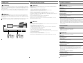
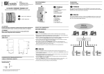
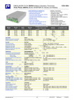
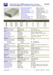
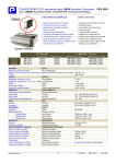
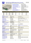
MS9- 7471 ed01
ENERDIS
16, rue Georges Besse Silic 44
92182 ANTONY Cedex - FRANCE
Tel. : (33) 01 75 60 10 30 • Fax : (33) 01 46 66 62 54
[email protected] • www.enerdis.fr
VUE D’ENSEMBLE
OVERVIEW
FONCTIONNEMENT DES LEDs
LEDS FUNCTIONALITY
n
F
ULYSCOM M-BUS
Susceptible de modification sans préavis.
Subject to change without prior notice.
Module de communication M-BUS - M-BUS communication module
o
p
F
q
r
- N OT I C E D ’ E M P LO I
GB - U S E R M A N U A L
FRANÇAIS
1. Bornes pour la connection M-Bus
2. Port optique pour la communication
3. Bouton SET DEFAULT
4. LED alimentation
5. LED communication
GB
Les deux LEDs qui sont sur la face avant du module fournissent des informations sur l’état de
l’alimentation et de la communication.
Two LEDs are available on the module front panel to provide power supply and communication
status.
F
FRANÇAIS
COULEUR LED SIGNAL
ENGLISH
1. M-Bus connection terminals
2. Optical COM port
3. SET DEFAULT key
4. Power supply LED
5. Communication LED
SIGNIFICATION
LED ALIMENTATION
-
Eteint
Module éteint
VERT
Toujours allumé
Module allumé
LED COMMUNICATION
ATTENTION!
La mise en service et l’utilisation de l’appareil doivent être faites seulement par
du personnel qualifié. Couper la tension avant toutes actions sur l’appareil.
WARNING!
Device installation and use must be carried out only by qualified staff.
Switch off the voltage before device installation.
FONCTION SET DEFAULT
SET DEFAULT FUNCTION
F
FRANÇAIS
La fonction SET DEFAULT permet de réinitialiser la configuration par défaut dans le module (par exemple
si l’adresse primaire M-Bus est oubliée).
Pour réinitialiser la configuration par défaut il faut appuyer au moins 5 s sur le bouton SET DEFAULT, la
LED de communication va clignoter vert / rouge 5 s. Après la LED de communication sera rouge sans
interruption pour indiquer qu’il faut relâcher le bouton.
BOITIER (mm)
SIZE (mm)
GB
90
45
SET DEFAULT function allows to restore on the module default settings (e.g. in case of M-Bus primary
address forgotten).
To restore default settings, keep SET DEFAULT key pressed for at least 5 s, communication LED will blink
green/red for 5 s. At the end of SET DEFAULT procedure, communication LED will be red continuously
indicating to release the key.
Adresse primaire M-Bus
M-Bus primary address
25
18
44
LONGUEUR DE DENUDAGE DES FILS
CABLE STRIPPING LENGTH
Raccordement des bornes
Terminals connection
0,5 Nm
5 mm
Utiliser un tournevis plat avec dimension 0,8x3,5 mm
Use a blade screwdriver with 0.8x3.5 mm size
65
VALEURS DEFAUT
DEFAULT VALUES
Module éteint
VERT
Clignotement lent
(temps éteint 2 s)
Communication M-Bus=OK
Communication avec compteur=OK
ROUGE
Clignotement rapide
(temps éteint 1 s)
Communication M-Bus=échec/absente
Communication avec compteur=OK
ROUGE
Toujours allumé
Communication avec compteur=échec/absente
VERT/ROUGE
Couleurs alternant par 5 s Réinitialisation en cours (SET DEFAULT)
ENGLISH
LED COLOUR
SIGNALLING
MEANING
POWER SUPPLY LED
-
Power OFF
The module is OFF
GREEN
Always ON
The module is ON
COMMUNICATION LED
000
Adresse secondaire M-Bus (Numéro ID)
M-Bus secondary address (ID number)
00000000
Vitesse de communication M-Bus
M-Bus communication speed
2400 bps
Masque des données décelés par le compteur
Mask of data detected on the counter by the module
Eteint
GB
ENGLISH
PROGRAMMATION
SETTINGS
-
-
Power OFF
The module is OFF
GREEN
Slow blink
(2 s OFF time)
M-Bus communication=OK
Counter communication=OK
RED
Fast blink
(1 s OFF time)
M-Bus communication=fault/missing
Counter communication=OK
RED
Always ON
Counter communication=fault/missing
GREEN/RED
Alternating colours for 5 s
SET DEFAULT procedure in progress
default
CONNEXION
CONNECTIONS
F
LOGICIEL M-BUS MASTER
M-BUS MASTER APPLICATION
FRANÇAIS
F
Entre le PC et le réseau M-Bus il faut installer une interface master pour adapter le port RS232/
USB au réseau. Le nombre maximum de modules connectables depend du type d’interface master
utilisée. Pour la connexion entre les appareils il est conseillé d’utiliser un cable blindé avec deux
conducteurs torsadés.
Après la connexion sur le réseau M-Bus il faut combiner chaque module M-BUS aux compteurs:
les rapprocher et les mettre l’un à côté de l’autre afin que les deux ports optiques soient en face.
GB
ENGLISH
A master interface is required between PC and the M-Bus network to adapt RS232/USB port to
network. The maximum number of modules to be connected can change according to the used
master interface. For the connection among the different modules, use a cable with a twisted pair
and a third wire.
After making M-Bus connections, combine each M-BUS module with a single counter: place them
side by side, perfectly lined up, with module optical port facing the counter optical port.
M-BUS MASTER est un logiciel applicatif qui permet de gérer la communication du module M-BUS.
Ce logiciel permet de:
• identifier et communiquer avec les modules M-BUS
• modifier la programmation des modules M-BUS branchés
• afficher les valeurs mesurées par le compteur connecté au module M-BUS
• programmer la cadence et le type de mesure à détecter
Pour utiliser le M-BUS MASTER suivre les instructions suivantes.
1. Connecter un ou plusieurs modules à la ligne M-Bus comme décrit précedemment.
2. Positionner un compteur avec chaque module afin que les ports optiques des deux soient face à
face.
3. Installer le M-BUS MASTER sur le PC.
4. Dès que l’installation est terminée, démarrer le M-BUS MASTER.
5. Faire une recherche des modules M-BUS sur le réseau.
Pour plus de details à propos de l’utilisation et l’installation du M-BUS MASTER, se référrer au
manuel d’instructions dans le CD joint.
GB
M+
M-
FRANÇAIS
ENGLISH
M-BUS MASTER is an application software which allows to manage M-BUS module communication.
With this application software it is possible to:
INTERFACE MASTER
MASTER INTERFACE
Réseau M-Bus
M-Bus network
RS232/USB
• detect and communicate with M-BUS modules
• change M-BUS module settings
• display the detected measurements of the energy counter connected to the M-BUS module
• set the measurement rate and type to be detected
To use M-BUS MASTER, follow the instructions.
1. Connect one or more modules on M-Bus network as previously described.
2. Place one counter for each M-BUS module: module optical port must face up to counter optical port.
3. Install M-BUS MASTER on PC.
4. At the end of installation, run M-BUS MASTER.
5. Carry out a search for the available M-BUS modules on the network.
For further details on M-BUS MASTER, refer to the user manual available on the enclosed CD.
CARACTERISTIQUES TECHNIQUES
TECHNICAL FEATURES
F
FRANÇAIS
Données conforme à la norme IEC 13757-1-2-3.
ALIMENTATION
Au travers du bus
COMMUNICATION M-BUS
Protocol: M-Bus
Port: 2 bornes à vis
Vitesse de communication: 300 à 38400 bps
COMMUNICATION SERIE
Type: port optique
Vitesse de communication: 38400 bps
CONFORMITE AUX NORMES
IEC 13757-1-2-3
IEC61000-6-2 Immunité environnements industriels:
IEC61000-4-2 Immunité aux décharges électrostatiques, IEC61000-4-3 Immunité aux champs
électromagnétiques rayonnés aux fréquences radioélectriques, IEC61000-4-4 Immunité aux
transitoires électriques rapides en salves, IEC61000-4-5 Immunité aux ondes de choc,
IEC61000-4-6 Immunité aux perturbations conduites, induites par les champs radioélectriques,
IEC61000-4-11 Immunité relatifs aux creux de tension, coupures brèves et variations de tension
IEC55011 classe A: perturbations radioélectriques des appareils industriels, scientifiques et médicaux
Securité: IEC60950
BORNES DE RACCORDEMENT
Bornes: 0,14 à 2,5 mm2
ENVIRONNEMENT
Température de fonctionnement: entre -15°C et +60°C
Température de stockage: entre -25°C et +75°C
Humidité relative: 80% max sans condensation
Indice de protection: IP20
GB
ENGLISH
Data in compliance with IEC 13757-1-2-3 standard.
POWER SUPPLY
Through bus connection
M-BUS COMMUNICATION
Protocol: M-Bus
Port: 2 screw terminals
Communication speed: 300...38400 bps
SERIAL COMMUNICATION
Type: optical port
Communication speed: 38400 bps
STANDARDS COMPLIANCE
IEC 13757-1-2-3
IEC 61000-6-2 Immunity for industrial environments:
IEC 61000-4-2 Electrostatic discharge, IEC 61000-4-3 RF radiated disturbance,
IEC 61000-4-4 Fast Transient (BURST), IEC 61000-4-5 Overvoltage (Surge),
IEC 61000-4-6 RF conducted disturbance, IEC 61000-4-11 Voltage dips and short interruptions,
IEC 55011 Class A: radiated emissions, conducted emissions
Safety: IEC 60950
DIAMETER WIRE FOR CONNECTION TERMINALS
Terminals: 0.14...2.5 mm2
ENVIRONMENTAL CONDITIONS
Operating temperature: between -15°C and +60°C
Storage temperature: between -25°C and +75°C
Humidity: 80% max without condensation
Protection degree: IP20