1
VOLKSWAGEN GOLF IV Serie "RHD"
1.6 i "101HP"
motore AEH / moteur AEH / AEH engine / AEH-Motor / motor AEH
motore AKL / moteur AKL / AKL engine / AKL-Motor / motor AKL
1.8i 20v "125HP"
motore AGN / moteur AGN / AGN engine / AGN-Motor motor AGN
1.8 GTI 20v "150HP"
motore AGU / moteur AGU / AGU engine / AGU-Motor / motor AGU
CODICE/CODE: 1VW19900E/1+MAN039/1
Istruzioni montaggio
condizionatore d’aria
Air conditioning installation
instructions
Instructions pour monter le
conditionneur d’air
Klimaanlage
Einbauanleitungen
Instrucciones para el montaje
del equipo aire acondicionado
40062 Molinella (Bologna) Italy - Via Nobili, 2 - Telefono (051) 69.06.111 (r.a.) - Telex 511640 - Telefax (051) 88.26.19
PRESCRIZIONI PER IL MONTAGGIO DELL' IMPIANTO A/C DIAVIA OBBLIGATORIE PER IL TECNICO INSTALLATORE, IL QUALE, NEL CASO DI LORO INOSSERVANZA, SARA' DIRETTAMENTE ED ESCLUSIVAMENTE RESPONSABILE VERSO IL CLIENTE.
1. verificare il corretto serraggio della bulloneria fornita e rimossa e comunque di tutte le parti interessate al montaggio dell' impianto A/C;
2. verificare che non vi siano perdite d' acqua, olio e aria su motore, freni, servosterzo, servofreno, ecc.;
3. verificare tutti i livelli dei liquidi. Qualora venga rimosso il radiatore acqua, ricaricare nel circuito lo stesso liquido scarico e, se è necessario un rabbocco,
aggiungere il liquido anticongelante prescritto. Assicurarsi inoltre che lo spurgo aria sia fatto come prescritto dal costruttore;
4. accertarsi della giusta tensione di tutte le cinghie, e verificare lo stato di usura di quelle non sostituite;
5. verificare che non si abbiano interferenze critiche in qualunque condizione di funzionamento. In particolare accertarsi che siano garantite distanze di sicurezza fra tutti i particolari soggetti a movimento relativo.
6. garantirsi che non si abbiano fregamenti con conseguente usura tra le parti mediante un corretto serraggio e posizionamento delle stesse;
7. assicurarsi del corretto isolamento elettrico, della corretta installazione dei fusibili e di tutte le parti dell' impianto elettrico;
8. dopo aver effettuato la carica del refrigerante effettuare una accurata ricerca di eventuali perdite di gas;
9. eseguire comunque ogni operazione secondo norme di buona tecnica;
10. se durante l' operazione di installazione dell' impianto, vengono praticati fori o tagli, è obbligatorio proteggere tali parti con prodotto antiruggine fornito
con l' impianto.
PRESCRIPTIONS POUR LE MONTAGE DE L’EQUIPEMENT A/C DIAVIA A RESPECTER PAR LE TECHNICIEN INSTALLATEUR, CAR S’IL NE LES OBSERVAIT
PAS, IL SERAIT DIRECTEMENT ET EXCLUSIVEMENT RESPONSABLE EVERS LE CLIENT.
1. vérifier que la visserie fournie ou manipulée ainsi que toutes les parties concernées par le montage de l’équipement A/C sont serrées et fixées correctement;
2. vérifier qu’il n’y a pas des fuites d’eau, d’huile ou d’air sur le moteur, les freins, la servodirection, le servofrein, etc..;
3. vérifier tous les niveaux. Si un complément de liquide de refroidissement est à effectuer, utiliser le même liquide que celui qui est dans le circuit. Si le
circuit a été vidangé, faire le plein avec le liquide préconisé par le constructeur.
4. s’assurer que la tension des courroies est correcte et vérifier l’état d’usure de celles qui n’on pas été remplacées;
5. vérifier qu’il n’ y a pas d’interférence critique dans toutes les conditions de fonctionnement. S’assurer en particulier que les distances de sécurité entre
toutes les pièces sujettes à un mouvement relatif sont respectées;
6. s’assurer qu’il n’y a pas de frottement provoquant l’usure entre les parties à cause d’un défaut de serrage ou de positionnement de celles-ci;
7. s’assurer que l’isolation électrique, l’ installation des fusibles et de toutes les parties du faisceau électrique sont correctes;
8. après avoir realisé la charge du réfrigérant, effectuer une recherche minutieuse de fuite éventuelle de gaz;
9. de toute façon, effectuer toutes les opérations dans les régles de l’art;
10. si durant l’opération de mise en place de l’équipement des trous ou des coupes sont pratiquées, il est impératif de les protéger avec le produit antirouille
fourni avec l’équipement.
INSTRUCTIONS FOR THE A/C SYSTEM FITTING TO BE FOLLOWED BY THE OPERATOR INSTALLING THE SYSTEM. IN CASE OF FAILURE TO COMPLY
WITH THEM, THE OPERATOR WILL BE DIRECTLY AND EXCLUSIVELY RESPONSIBLE TO THE CUSTOMER.
1. check the proper tightening of the supplied nuts and bolts and removal, and otherwise, of all parts involved in the assembly of the A/C system;
2. check that there are no water, oil or air leaks on the engine, brakes, power steering, power brakes, etc.;
3. check the level of all liquids. Should the water radiator be removed, refill the circuit with the same discharged liquid and, if it is necessary to top up ,
add the prescribed antifreeze liquid. Furthermore, make sure that the bleeding is carried out as prescribed by the manufacturer;
4. check the proper tension of all the belts and check the state of wear on those which have not been replaced;
5. check that there is no critical interference under any function condition. In particular check that the safety distances between all parts subject to relative
movement are guaranteed;
6. ensure that there is no rubbing between parts with consequent wear by means of proper tightening and positioning of the parts themselves;
7. check that electric insulation, fuse installation and all parts of the electric system are correct;
8. after the refrigerant charge, make a careful search for any gas leaks;
9. carry out all operations according to the rules of good technology;
10. should any holes or cuts be made during installation of the system, it is absolutely necessary to protect such parts with the rustpreventer supplied with
the system.
VERBINDLICHE VORSCHRIFTTEN FÜR DEN EINBAUTECHNIKER BEI NICHTBEACHTUNG ERLISCHT JEDER ANSPRUCH AUF GARANTIE UND ERSATZTEILLIEFERUNG.
1. Jede DIAVIA-Klimaanlage ist gemäß der beigefügten Einbaueinleitung einzubauen;
2. Bei allen Einbauteilen der Klimaanlage ist auf die vorgeschriebene Anbringung an den vorgesehenen Punkten zu achten, ebenso auf die erforderliche Bewegungsfreiheit der einzelnen Aggregatteile.
3. Bei korrekter Positionierung und Befestigung der Teile sind Abnutzungen durch Reibung ausgeschlossen. Eventuell auftretende Störungen sind unverzüglich zu überprüfen;
4 . Alle Einbauteile, sowie die verwendeten Schrauben und Muttern sind auf ihre korrekte Spannung und festen Sitz hin zu überprüfen.
5. Alle Teile der elektrischen Anlage sowie die Sicherung sind auf Isolation und korrekte Installation hin zu überprüfen;
6. Nach Auffüllung der Klimaanlage mit dem Kältemittel muß die gesamte Anlage auf eventuelle Verluste von Gas überprüft werden;
7. Bei Inbetriebnahme der Klimaanlage ist die korrekte Spannung aller Keilriemen zu überprüfen. Nicht ersetzte Keilriemen sind auf ihre Abnutzung hin zu
untersuchen.
8. Nach Einbau der Klimaanlage ist zu überprüfen, daß Motor,Bremsen, Servolenkung und Servobremse keine Wasser-, Oel-,oder Luftverluste aufweisen;
9. Vor Übergabe des Wagens muß das Niveau aller Flüssigkeitsanzeigen überprüft werden. Falls beim Klimaanlageneinbau der Wasserkühler ausgebaut wurde, ist die entnommene Flüssigkeit im Umlauf wieder aufzufüllen und das erforderliche Frostschutzmittel nachzufüllen.
10. Im Falle, daß während der Installationsarbeiten der Anlage, Bohrungen oder Schnitte durchgeführt werden, ist es unbedingt notwendig, diese Teile mit
dem bei der Anlage mitgelieferten Rostschutzmittel zu schützen.
PRESCRIPCIONES PARA EL MONTAJE DE LA INSTALACIóN A/C OBLIGATORIAS PARA EL TECNICO INSTALADOR; EN CASO DE SUS INOBSERVANCIA,
ÉL SERÁ DIRECTAMENTE Y EXCLUSIVAMENTE RESPONSABLE HACIA EL CLIENTE.
1. verificad que los tornillos en dotación, los removidos y de todos modos todas las partes que se emplean para el montaje de la instalación A/C sean bien
apretadas;
2. verificad que no se producan pérdidas de agua, de aceite y de aire sobre el motor, los frenos, el servofreno, la servo dirección, etc;
3. verificad todos los niveles de los líquidos. En caso se remueva el radiador de agua, recargad en el circuito el mismo líquido descargado, y se es necesario
un relleno añadid el líquido anticongelamiento prescrito. Además, averiguad que el expurgo de aire sea hecho como está prescrito por el constructor;
4. averiguad que todas las correas sean bien tendidas y verificad el estado de desgaste de las que no han sido reemplazadas;
5. verificad que no se producan graves interferencias en cualquier condición de funcionamiento. En particular verificad de que sean garantizadas las distancias
de seguridad entre todos los elementos expuestos a movimiento relativo;
6. averiguad que no se producan fricaciones con consiguiente desgaste de las partes , apretándolas correctamente y poniendo esas mismas en posición
correcta;
7. verificad el correcto aislamiento eléctrico, el correcto montaje de los fusibles y de todas las partes de la instalación eléctrica;
8. después de haber introducido el refrigerante, efectuad una busca diligente acerca de posibles pérdidas de gas;
9. de todos modos, efectuad cada operación según las normas de la mejor tecnología;
10. si durante la operación de puesta de la instalación se hacen agujeros o cortes les aconsejamos protejan estos puntos con un producto antioxido abastecido
con la instalación.
INDICE / INDEX / INDEX / INHALTSVERZEICHNIS / INDICE
Pag. / Page / Seite
NOTE DI MONTAGGIO
NOTES DE MONTAGE
FITTING NOTES
EINBAUANLEITUNGEN
NOTAS DE MONTAJE
4
TABELLA COPPIE DI SERRAGGIO
TABLEAU DES COUPLES DE SERRAGE
DRIVING TORQUES TABLE
TABELLE DER VERSCHRAUBUNSPAARE
TABLAS PARES DE TORSION
5
MONTAGGIO COMPRESSORE
POSE DU COMPRESSEUR
COMPRESSOR FITTING
KOMPRESSOREINBAU
MONTAJE COMPRESOR
7
MONTAGGIO CONDENSATORE
POSE DU CONDENSEUR
CONDENSER FITTING
KONDENSATOREINBAU
MONTAJE CONDENSADOR
15
MONTAGGIO FILTRO ESSICCATORE
POSE DU FILTRE DESHYDRATEUR
RECEIVER DRIER ASSEMBLY
TROCKNERFILTER EINBAU
MONTAJE DEL FILTRO SECADOR
20
MONTAGGIO COMPONENTI A.C. NELL’ABITACOLO
POSE DES COMPOSANTS A.C. DANS L’HABITACLE
A.C. COMPONENTS ASSEMBLY IN THE PASSENGER COMPARTMENT
EINBAU DER KLIMAANLAGEN-BESTANDTEILE IM WAGENINNEREN
MONTAJE COMPONENTES A.C. EN EL HABITACULO
23
COLLEGAMENTO TUBI GAS
INSTALLAZIONE COMPONENTI ELETTRICI NEL VANO MOTORE
RACCORDEMENT DES TUYAUX GAZ
INSTALLATION COMPOSANTS ELECTRIQUES DANS LE COMPARTIMENT MOTEUR
GAS PIPE CONNECTION
INSTALLATION OF ELECTRICAL COMPONENTS IN THE ENGINE COMPARTMENT
KAELTEMITTELSCHLAUCHVERBINDUNG
INSTALLATION DER ELEKTRISCHEN TEILE IM MOTORRAUM
CONEXION TUBOS GAS
INSTALACION COMPONENTES ELECTRICOS EN EL COMPARTIMENTO MOTOR
45
SCHEMA IMPIANTO ELETTRICO
SCHEMA DE L’INSTALLATION ELECTRIQUE
WIRING DIAGRAM
SCHEMA DER ELEKTRISCHEN ANLAGE
ESQUEMA INSTALLACION ELECTRICA
70-71
3
(I)
NOTE:
Lo schema di montaggio illustra l'impianto AC e comprende a volte dei componenti accessori (es. minimo veloce, radiatore, ecc.) che debbono però
essere ordinati separatamente, in aggiunta all'impianto base, consultando il ns. listino.
Tutte le indicazioni relative alla DESTRA ed alla SINISTRA sono riferite al senso di marcia: SINISTRA = lato guida, DESTRA = lato passeggero.
Tutti i numeri presenti nel testo e nelle figure, indicano componenti forniti del condizionatore e vanno pertanto riferiti ai kit di
figg.1A,1B,1C,1D,1.1D,1E,1.1E.
Tutte le viti e i raccordi tubi gas vanno bloccati senza superare i valori massimi delle coppie di serraggio indicati nella tabella seguente, se non
diversamente specificato nel testo.
Per il corretto funzionamento ed affidabilità delle cinghie installate, eseguire le seguenti operazioni:
a) Avviare il motore con impianto AC inserito e dopo 15 minuti circa di funzionamento, ritensionare le cinghie.
b) La stessa operazione di tensionamento va ripetuta dopo 1500 Km dalla installazione dell'impianto AC.
Nella vettura provvista di dispositivi di sicurezza tipo AIR BAG o PROCON-TEN® lo smontaggio di tali componenti deve essere effettuato attenendosi
alle disposizioni delle rispettive case automobilistiche.
La quantità di gas R134a necessaria per la carica dell'impianto è di Kg. 0.750 (±0,025).
(F)
REMARQUE :
Le manuel d’instructions illustre l’équipement A/C et il comprend quelque fois des composants accessoires (par ex.: ralenti-accéléré, radiateur, etc.)
qui doivent cependant être commandés séparément, en plus de l’équipement de base, en consultant notre catalogue.
Toutes les indications de DROITE et de GAUCHE se réfèrent à la direction de marche: GAUCHE = côté conducteur, DROITE = côté passager.
Tous les numéros du texte et des figures indiquent les composants du conditionneur fourni. ls doivent par conséquent être comparés aux kits des
fig.1A,1B,1C,1D,1.1D,1E,1.1E.
Toutes les vis et les raccords des tuyaux gaz doivent être bloqués sans dépasser les valeurs maximales des couples de serrage indiqués dans le
tableau suivant, s’il n’y a pas de précision contraire.
Pour obtenir le bon fonctionnement et la fiabilité des courroies installées, effectuer les opérations suivantes:
a) Faire démarrer le moteur avec l’équipement d’air conditionné enclenché et après 15 minutes environ, tendre à nouveau les courroies.
b) Il faut répéter l’opération de tension de courroie 1500 Km après le montage de l’air conditionné.
Sur les voitures munies des systèmes de sécurité type AIR BAG ou PRECON-TEN®, le démontage de ces composants doit être effectué en suivant
scrupuleusement les dispositions de chaque Constructeur.
La quantité de gaz R134a nécessaire pour charger l’équipement est de Kg. 0.750 (±0,025).
(GB)
NOTE :
This instruction manual illustrates the A/C system and at times, includes accessories (ex.: idle-speed control, radiator, etc.). These parts, however,
must be ordered separately in addition to the basic kit according to our price list.
All references to RIGHT and LEFT hand are related to the driving direction: LEFT = driver’s side, RIGHT = passenger’s side.
All numbers quoted in the text and under the photos refer to the supplied componets of the air conditioning unit. One must therefore refer to the
kits shown in the figg.1A,1B,1C,1D,1.1D,1E,1.1E.
All screws and gas pipes fittings must be locked without exceeding the maximum value of the driving torques indicated in the following table, if
not otherwise specified in the text.
Once fitting has been completed, spray an anticorrosive trasparent product on the installed metal parts.
To ensure functioning and reliability of installed belts, carry out the following procedures :
a) Start motor with A/C system switched on and after about 15 minutes adjust belt tension.
b) The same adjustment procedure should be repeated after 1500 Km from the installation of the A/C system.
In those vehicles with AIR-BAG or PRECON-TEN® safety devices, these components must be removed carefully following the instructions given by
the car manufacturers.
The quantity of R134a gas necessary for the system charge is Kg. 0.750 (±0,025).
(D)
ANMERKUNG:
Die Einbauanleitung beschreibt die Klimaanlage, in einigen Fällen gehören jedoch Bauteile hinzu (z.B. Leerlaufvorrichtung, Kühler, Lüfter usw.) die
separat zur Grundausstattung der Anlage zu bestellen sind, da es sich um Zusatzteile handelt, siehe unsere Preisliste. Alle Hinweise auf RECHTS
und LINKS beziehen sich auf die Fahrtrichtung: LINKS= Fahrerseite, RECHTS = Beifahrerseite.
Alle Ziffern im Text und der Abbildung1A,1B,1C,1D,1.1D,1E,1.1E beziehen sich auf vorhandene Bestandteile des Bausatzes.
Alle Schraub- und Schlauchverbindungen sind,falls nicht anders angegeben, gemäß unten stehender Tabelle anzuziehen. Nach beendetem Einbau
ist es ratsam auf die eingebauten Metallteile Schutzwachs aufzusprühen, um Rostbildungen zu verhindern. Für Funktions-und Lebensdauer der Keilriemen ist folgendes zu beachten:
a) den Motor mit eingeschalteter Klimaanlage anlassen und nach ca. 15 Minuten der Funktion, die Riemen spannen.
b) Nach 1500 Km Riemen nachspannen.
Bei Fahrzeugen mit Sicherheitsvorrichtung wie AIR BAG oder PROCON-TEN® muß der Ausbau derselben, nur nach den Anleitungen der Automobilhäuser durchgeführt werden.
Die notwendige Menge des Gas R134a für die Auffüllung der Klimaanlage ist (±0,025) 0.750 Kg.
(E)
NOTAS:
El manual de instrucciones ilustra la instalación A.C. y a veces comprende componentes accesorios (por ejemplo: minimo acelerado, radiador, etc.)
que se deben ordenar separadamente, como agregado a la instalación base consultando nuesto listin.
Todas las indicaciones relativas a la DERECHA y a la IZQUIERDA se refieren al sentido de marcha: IZQUIERDA= lado conductor: DERECHA= lado
pasajero.
Todos los números presentes en el texto y en las figuras indican componentes abastecidos del equipo de aire acondicionado y se refieren a los kits
de las figuras 1A,1B,1C,1D,1.1D,1E,1.1E.
Todos los tornillos y los racordes tubos gas tienen que ser bloqueados sin superar los valores máximos de las parejas de cerraje indicados por el
cuadro que sigue, si no diversamente especificado.
Una vez efectuado el montaje se aconseja aplicar en las paredes metálicas instaladas un producto spray transparente, de protección antioxidante.
Para la correcta puesta en marcha y fiabilidad de las correas montadas llevar a cabo las operaciones siguientes:
a) Arrancar el motor con el equipo de aire acondicionado conectado y después de 15 minudos de funcionamiento, volver a tensar las correas.
b) Hay que volver a repetir la misma operación de tensar la correa después de 1500 Kms. a partir del montaje del equipo.
En los coches provistos de dispositivos de seguridad modelo AIR BAG o PROCON-TEN® el desmontaje de estos componentes se debe efectuar
siguiendo las disposiciones de las respectivas casas automobilisticas.
La cantidad de gas R134a necesaria para cargar el equipo es de Kg. 0.750 (±0,025).
4
VALORI MASSIMI COPPIE DI SERRAGGIO PER VITI (in N.m)
VALEURS MAXIMUM DES COUPLES DE SERRAGE POUR LES VIS (en N.m)
MAXIMUM VALUES OF THE DRIVING TOURQUES FOR SCREWS (in N.m.)
MAXIMUMWERT DER VERSCHRAUBUNGEN FÜR DIE SCHRAUBEN (in N.m)
VALORES MAXIIMOS PAREJAS DE CERRAJE PARA TORNILLOS (en N.m)
Apertura in chiave (mm)
Ouverture en clef (mm)
Wrench opening (mm)
Schlüsselöffnung (mm)
Abertura en llave (mm)
Classe dell’acciaio della vite
Classe de l’acier de la vis
Screw steel class
Stahlklassifizierung der Schrauben
Clase del acero del tornillo
Filettatura
Filetage
Thread
Gewinde
Filetadura
5.8
8.8
10.9
M 4(x0.7)
1.8
2.9
4.2
M 5(x0.8)
3.4
5.5
7.5
8
M 6(x1)
6
10
13
10
M 7(x1)
11
16
21
11
M 8 (x1.25)
14
22
30
13
M 8x1
15
23
32
13
M10(x1.5)
27
45
61
17
M10 x1.25
31
50
67
17
M10 x1
33
53
71
17
M12 x1.5
51
78
105
19
M12 x1.25
60
94
125
19
M12 x1.75
84.8
119
143
19
M14 x1.5
80
120
165
22
M16 x1.5
120
185
255
24
M18 x1.5
165
265
350
27
M20 x1.5
225
360
490
30
M22 x1.5
295
480
640
32
M24 x2
390
610
805
36
RACCORDO
RACCORD
FITTINGS
VERBINDUNG
RACORDE
7
VALORI MASSIMI COPPIE DI SERRAGGIO
PER RACCORDI TUBI GAS (in N.m.)
VALEURS MAXIMUM DES COUPLES DE SERRAGE
POUR RACCORDS TUYAUX DU FREON (en N.m.)
MAXIMUM VALUES OF THE DRIVING TORQUES
FOR GAS PIPES FITTINGS (in N.m.)
MAXIMUMWERT DER VERSCHRAUBUNGSPAARE FÜR DIE
VERBINDUNGEN DER KÄLTEMITTELSCHLÄUCHE (in N.m.)
VALORES MAXMOS PAREJAS DE CERRAJE
PARA RACORDES TUBOS GAS (en N.m.)
5/8”
15.4÷17
3/4”
15.4÷17
7/8”
24.4÷27
1”
24.4÷27
- Lubrificare tutti i raccordi e gli O.R. con il nuovo
olio refrigerante prima di collegarli
- Graisser tous les raccords et les O.R. avec le nuveau huile réfrigérant avant de les raccorder
- Per avvitare a fondo o allentare i raccordi tubi gas usare due
chiavi per bilanciare coppia di torsione
- Pour visser à fond ou desserrer les raccords des tuyaux gaz,
utiliser le deux clés pour équilibrer le couple de torsion
-Lubricate all fittings and O-rings with new refrigerant oil before
connecting them
- Alle Verbindungsstücke und OR-Ringe vor deren Verbindung
mit dem neuen Kühlmittellöl ölen
- Lubrificar todos los empalmes y los O.R. con el nuevo aceite
refrigerante antes de conectarlos
- When tightening or loosening the fittings of the gas pipes, use two wrenches to equilize the torsion couple
- Um die Verbindungsstücke der Kältemittelschläuche gleichmäßig festzuschrauben oder zu lockern, zwei Schlüssel für das Verschraubungspaar verwenden
- Para enroscar a fondo o aflojar los empalmes tubos gas se deben usar dos
llaves para balancear el par de torsión
- Tagliare con utensile appropriato al materiale
- Couper à l’aide d’outil approprié
- Cut with a device suitable for the material
- Mit dem Material entsprechendem Werkzeug
schneiden
- Cortar con herramienta apropiada al material
-
5
Stagnare
Étamer
Tin
Verzinnen
Estañar
(I)
ATTENZIONE:
Nelle vetture dotate di marmitta catalitica è necessario controllare IN OGNI CASO la posizione di uscita dall'abitacolo del tubo scarico
condensa dell' evaporatore.
- Se il tubo dovesse risultare in prossimità della marmitta, in modo da essere investivo dalla fascia di calore emanata dalla marmitta
stessa, occorre tagliare il tubo subito dopo la sua uscita dall'abitacolo (riquadro "A").
- Se il tubo è provvisto di rompi-goccia (riquadro "B") bisogna bloccare il tubo ad elementi della vettura in posizione più distanziata
possibile dalla marmitta.
(F)
ATTENTION:
Sur les voitures munies de pot d’échappement à catalyse, il est nécessaire de TOUJOURS contrôler la position du dégorgement pour
condensat de l’évaporateur en sortie de l’habitacle.
- Dans le cas où le tuyau serait en proximité du pot d’échappement, ou dans la zone de trop forte chaleur, il faudrait couper le tuyau
immédiatement après le point de sortie de l’habitacle (illustration "A").
- Si le tuyau est muni de brise-gouttes (illustration "B"), il est nécessaire de le bloquer aux éléments de la voiture dans une position
qui est la plus lointaine possible du pot d’échappement.
(GB)
CAUTION:
The position where the evaporator condensate drainage hose comes out of the passenger compartment MUST BE ALWAIS CHECKED
whenever the vehicle has a catalytic converter.
- If the pipe is close enough to the converter to be heated by the heat generated by the converter itself, cut it down to just below
the point where it comes out of the passenger compartment (detail "A").
- If the pipe is provided with an anti-dripping device (detail "B"), the pipe must be secured to the vehicle at a point as far away from
the catalytic converter as possible.
(D)
ACHTUNG:
Bei Fahrzeugen mit Katalysator-Auspuff ist es notwendig, IN JEDEM FALL die Position des Kondenswasserabflußaustritts des Verdampfers am Austritt aus dem Fahrzeuginnenraum zu kontrollieren.
- Sollte der Schlauch in der Nähe des Auspuffs liegen, sodaß dieser im Hitzebereich des Auspuffs liegt, den Schlauch sofort am
Austritt aus dem Fahrzeuginnenraum abschneiden (Ausschnitt "A").
- Falls der Schlauch mit einer Tropfabdeckung ausgestattet ist (Ausschnitt "B"), den Schlauch so weit als möglich vom Auspuff verlegen und an Elemente des Fahrzeugs befestigen.
(E)
ATENCIÓN:
En los coches dotados de silenciador de escape catalítico es necesario controlar SIEMPRE la posición de salida del habitáculo del
tubo de drenaje condensación del evaporado.
- Si el tubo debiera resultar próximo al silenciador de escape y fuera embestido por la faja de calor que emana el silenciador mismo,
es necesario cortar el tubo después que sale del habitáculo (recuadro "A").
- Si el tubo está provisto de protección contra las gotas (recuadro "B") es necesario bloquear el tubo a elementos del coche en una
posición lo más lejos posible del silenciador del escape.
6
MONTAGGIO COMPRESSORE / POSE DU COMPRESSEUR / COMPRESSOR FITTING
KOMPRESSOREINBAU / MONTAJE COMPRESOR
MATERIALE FORNITO / MATERIEL FOURNI / SUPPLIED MATERIAL / GELIEFERTES MATERIAL / MATERIAL ABASTECIDO
FIG.1A
3
4
2
6
1
5
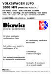
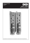
(I)
Vista componenti montaggio compressore.
(F)
Vue des composants nécessaires au montage du compresseur.
(GB)
View of the components for the compressor assembly.
(D)
Ansicht der Einbauteile des Kompressors.
(E)
Vista de los componentes para el montaje
del compresor.
7
1.1
ELENCO MATERIALE FORNITO / LISTE DU MATERIEL FOURNI / LIST OF SUPPLIED MATERIALS
VERZEICHNIS DES GELIEFERTEN MATERIALS / LISTA MATERIAL ABASTECIDO
Pos.
1
1.1
Descrizione / Description / Description / Beschreibung / Descripción
Compressore / Compresseur / Compressor / Kompressor / Compresor
Codice / Code
Kode / Codigo
084014314
Cablaggio Packard per compressore / Câblage Packard pour compresseur / Packard wiring for compressor/
Packard Kabelstrang für Kompressor / Cableado Packard para compresor
028839
2
Staffa / Etrier / Bracket / Bügel / Abrazadera
0021332
3
Puleggia galoppino / Poulie de renvoi / Idle pulley / Leitrollenriemenscheibe / Polea directriz
004052DV
4
Distanziale / Entretoise / Shim / Absandsstück / Distanziador φ11xφ20x22
009439ZN
5
Cinghia / Courroie / Belt / Riemen / Correa 6Kx1440
013541
6
Distanziale / Entretoise / Shim / Absandsstück / Distanziador φ10,5xφ22x32
009849
7
Bulloneria / Boulonnerie / Nuts and bolts / Schraubensatz / Tornillería
7
037AU51
OPERAZIONI PRELIMINARI / OPERATIONS PRELIMINAIRES / PRELIMINARY OPERATIONS
VORBEREITUNGSARBEITEN / OPERACIONES PRELIMINARES
(I)
– Smontare
– Smontare
– Smontare
– Smontare
– Smontare
– Smontare
– Smontare
la batteria e relativo supporto.
le grembialine inferiori di protezione motore e cinghia di trasmissione.
il paraurti anteriore.
la calandra frontale sede radiatore.
il gruppo radiatore/elettroventola dalla calandra.
la calotta superiore di protezione motore.
ed eliminare la cinghia di trasmissione.
(F)
– Démonter
– Démonter
– Démonter
– Démonter
– Démonter
– Démonter
– Démonter
la batterie et son support.
les écrans inférieurs de protection du moteur et de la courroie de transmission.
le pare-chocs antérieur.
le tablier avant frontal emplacement radiateur.
le groupe radiateur/électroventilateur du tablier avant.
la calotte supérieure de protection du moteur.
et éliminer la courroie de transmission.
(GB)
– Remove
– Remove
– Remove
– Remove
– Remove
– Remove
– Remove
the battery and its support.
the lower engine protection screen and transmission belt.
the front bumper.
the front radiator grill.
the radiator/electric fan unit from the grill.
the upper engine protection hood.
and discard the transmission belt.
(D)
– Batterie und entsprechende Halterung ausbauen.
– Untere Motor- und Antriebsriemenabdeckungen ausbauen.
– Vordere Stoßstange abbauen.
– Kühlergrill Sitz des Kühlers ausbauen.
– Kühler-/Elektrogebläseeinheit von der Kühlerverkleidung ausbauen.
– Obere Motorabdeckung ausbauen.
– Antriebsriemen ausbauen und ausscheiden.
(E)
– Desmontar
– Desmontar
– Desmontar
– Desmontar
– Desmontar
– Desmontar
– Desmontar
la batería y relativo soporte.
la pantalla inferior de protección motor y correa de trasmisión.
paragolpes anterior.
la calandria frontal (sede radiador).
el grupo radiador/Eléctroventilador de la calandria.
el casquete superior de protección motor.
y eliminar la correa de trasmisión.
8
a
b
a
b
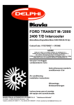
FIG.2A
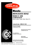
(I)
Vista dei fori passanti "a" e "b" predisposti sul supporto alternatore-pompa idroguida, da utilizzare per il fissaggio del compressore.
(F)
Vue des trous passants "a" et "b" prévus sur le support de l’alternateur/pompe direction assistée, à utiliser pour le fixage du compresseur.
(GB)
View of the holes "a" and "b" arranged on the alternator/hydraulic power steering pump support. They are used to secure the compressor.
(D)
Ansicht der an der Drehstromgenerator-Servolenkungshalterung vorhandenen durchgehenden Bohrungen "a" und "b". Diese sind zur
Befestigung des Kompressors zu verwenden.
(E)
Vista de los orificios pasantes "a" y "b" predispuestos en el soporte Alternador/Bomba servodirección, a utilizar para el ajuste del
compresor.
9
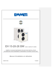
FIG.3A
(I)
Rappresentazione
schematico-riassuntiva dello staffaggio
compressore con indicazione della relativa
bulloneria di fissaggio.
La sequenza di montaggio dei singoli componenti è descritta
nella documentazione
fotografica seguente.
(F)
Réprésentation schèmatique-récapitulative
des
étriers
compresseur avec indications de la boulonnerie
de
fixage
correspondante.
La
sequence de montage
des composants est
décrite dans les photos qui suivent.
(GB)
Recapitulatory diagram of the compressor bracketing and indications of the fixing nuts and bolts. The assembly sequence of compponents is described in the following photos.
(D)
Schematische Gesamtdarstellung der Verbügelung des Kompressors, mit Hinweisen der entsprechenden Befestigungsschrauben und
-muttern. Die Reihenfolge des Einbaus der einzelnen Bestandteile ist in der folgenden fotografischen Dokumentation beschrieben.
(E)
Representación esquematica recopilativa del anclaje compresor, con indicaciones de la relativa tornilleria de ajuste. La sequencia de
los componentes está descrita por la documentación fotográfica que sigue.
BULLONERIA DA UTILIZZARE / BOULONNERIE A UTILISER / NUTS AND BOLTS TO BE USED
ZU BENUTZENDER SCHRAUBENSATZ / TORNILLERIA A UTILIZAR
Pos.
Descrizione / Description / Description / Beschreibung / Descripción
8
Vite TE / Vis à tête à six pans / Hexagonal head screw / Sechskantschraube / Tornillo cabeza hexagonal M10x140
9
Vite TE / Vis à tête à six pans / Hexagonal head screw / Sechskantschraube / Tornillo cabeza hexagonal M10x130
10
Vite TE / Vis à tête à six pans / Hexagonal head screw / Sechskantschraube / Tornillo cabeza hexagonal M10x40
11
Rondella piana / Rondelle plate / Plain washer / Flache U-Scheibe / Arandela llana φ10
12
Dado autobloccante / Ecrou autobloquant / Self-locking nut / Selbstsperrende Mutter / Tuerca autobloqueante M10
13
Vite TE / Vis à tête à six pans / Hexagonal head screw / Sechskantschraube / Tornillo cabeza hexagonal M10x70
14
Rondella conica / Rondelle conique / Conical washer / Kegelscheibe / Arandela cónica φ10
10
10
12
1
9 12
11
8
(I)
Fissare il compressore "1" al supporto originale dell’alternatore e della pompa idroguida, unitamente alla staffa "2" di support
loppino, utilizzando bulloneria M10 e distanziale "6" forniti.
(F)
lopin,
à l’aide de la boullonerie M10 et de entretoise "6" fournies.
Secure the compressor "1" to the original alternator and hydraulic power steering pump suport together with guide support bracket
(D)
Den Kompressor "1" an Original-Halterung des Drehstromgenerators und der Servolenkungspumpe zusammen an Halter "2" der Lei-
(E)
Fijar el compresor "1" al soporte original del alternador y de la boma servodirección, junto a la abrazadera "2" de soporte dire
utilizando tornilleria M10 y distanciador "6" abastecidos.
BULLONERIA DA UTILIZZARE / BOULONNERIE A UTILISER / NUTS AND BOLTS TO BE USED
Pos.
Descrizione / Description / Description / Beschreibung / Descripción
Vite TE / Vis à tête à six pans / Hexagonal head screw / Sechskantschraube / Tornillo cabeza hexagonal M10x140
9
10
Vite TE / Vis à tête à six pans / Hexagonal head screw / Sechskantschraube / Tornillo cabeza hexagonal M10x40
Rondella piana / Rondelle plate / Plain washer / Flache U-Scheibe / Arandela llana φ
12
Dado autobloccante / Ecrou autobloquant / Self-locking nut / Selbstsperrende Mutter / Tuerca autobloqueante M10
11
4
13
2
14
FIG.5A
(I)
Fissare la puleggia galoppino "3" alla staffa "2" mediante vite e rondella fornite, con interposizione del distanziale "4" fra puleggia
e staffa.
(F)
Fixer la poulie de renvoie "3" à la bride "2" à l’aide de la vis et de la rondelle fournies, en effectuant aussi l’interposition de l’entretoise
"4" entre la poulie et la bride.
(GB)
Secure the idle pulley "3" to bracket "2" using supplied screw and washer and interposing spacer "4" between pulley and bracket.
(D)
Leitrollenriemenscheibe "3" an Bügel "2" mit gelieferter Schraube und U-Scheibe und Zwischenlegung des Abstandstücks "4"
zwischen Riemenscheibe und Bügel, befestigen.
(E)
Fijar la polea directriz "3" a la abrazadera "2" mediante tornillo y arandela abastecidos, con interposición del distanciador "4" entre
polea y abrazadera.
BULLONERIA DA UTILIZZARE / BOULONNERIE A UTILISER / NUTS AND BOLTS TO BE USED
ZU BENUTZENDER SCHRAUBENSATZ / TORNILLERIA A UTILIZAR
Pos.
Descrizione / Description / Description / Beschreibung / Descripción
13
Vite TE / Vis à tête à six pans / Hexagonal head screw / Sechskantschraube / Tornillo cabeza hexagonal M10x70
14
Rondella conica / Rondelle conique / Conical washer / Kegelscheibe / Arandela cónica φ10
12
VISTA FRONTALE / VUE FRONTALE
FRONT VIEW / FRONTALANSICHT
VISTA FRONTAL
M
G
3
1
A
5
5
I
VISTA DAL BASSO / VUE D’EN BAS
VIEW FROM BELOW / ANSICHT VON UNTEN
VISTA DESDE EL BAJO
1
FIG.6A
(I)
Montare la cinghia di trasmissione fornita "5" in sostituzione della cinghia originale eliminata, collegando puleggia motore "M", puleggia pompa idroguida "I", puleggia galoppino "3", puleggia compressore "1", puleggia alternatore "A", puleggia tendicinghia originale "G".
Per un corretto allineamento della cinghia, posizionarla sulla 2ª gola della elettropuleggia del compressore, come indicato in riquadro.
(F)
Monter la courroie de transmission fournie "5" en remplacement de la courroie d’origine éliminée, en connectant la poulie moteur
"M", poulie pompe direction assistée "I", poulie de renvoi "3", poulie compresseur "1", poulie alternateur "A", poulie tension de
courroie d’origine "G".
Pour obtenir un alignement correct de la courroie, il est nécessaire de la positionner sur la deuxième gorge de l’électropoulie du compresseur, comme indiqué par l’encadré.
13
FIG. 6A
(GB)
Install the supplied transmission belt "5" to replace the original one which was discarded. Connect the following parts: driving pulley
"M", hydraulic power steering pump pulley "I", idle pulley "3", compressor pulley "1", alternator pulley "A", original belt tightening
pulley "G".
To properly align the belt, position it on the 2nd groove on the compressor pulley as indicated in the inset.
(D)
Gelieferten Antriebsriemen "5" anstelle des ausgeschiedenen Original-Riemens einbauen und Motorriemenscheibe "M", Riemenscheibe der Servolenkungspumpe "I", Leitrollenriemenscheibe "3", Kompressor-Riemenscheibe "1", Drehstromgenerator-Riemenscheibe
"A", Original-Spann-Riemenscheibe "G" montieren.
Für eine korrekte Ausrichtung des Riemens ist dieser auf die 2. Rille der Elektroriemenscheibe des Kompressors, wie im Ausschnitt
gezeigt, zu positionieren.
(E)
Montar la correa de trasmisión abastecida "5" en sustitución de la correa original eliminada, conectando polea motor "M", polea
Bomba Servodirección "I", polea directriz "3", polea compresor "1", polea alternador "A", polea tensor de correa original "G".
Para una correcta alineación de la correa, colocarla en el 2° canal de la Eléctropolea del compresor, como se indica en el recuadro.
14
MONTAGGIO CONDENSATORE / POSE DU CONDENSEUR / CONDENSER FITTING
KONDENSATOREINBAU / MONTAJE CONDENSADOR
MATERIALE FORNITO / MATERIEL FOURNI / SUPPLIED MATERIAL / GELIEFERTES MATERIAL / MATERIAL ABASTECIDO
FIG.1B
(I)
Vista componenti montaggio condensatore.
31
(F)
Vue des composants nécessaires au montage
du condenseur.
33
32
(GB)
View of the components for the condenser assembly.
(D)
Ansicht der Einbauteile des Kondensators.
35
(E)
Vista de los componentes para el montaje del
condensador.
36
34
37
ELENCO MATERIALE FORNITO / LISTE DU MATERIEL FOURNI / LIST OF SUPPLIED MATERIALS
VERZEICHNIS DES GELIEFERTEN MATERIALS / LISTA MATERIAL ABASTECIDO
Pos.
Descrizione / Description / Description / Beschreibung / Descripción
Codice / Code
Kode / Codigo
31
Condensatore / Condenseur / Condenser / Kondensator / Condensador
022301OR
32
Staffa sinistra di supporto condensatore / Etrier support condenseur gauche / Left condenser support
bracket / Kondensator-Haltebügel, links / Abrazadera izquierda de soporte condensador
0811913/1
33
Staffa destra di supporto condensatore / Etrier support condenseur droit / Right condenser support bracket / Kondensator-Haltebügel, rechts / Abrazadera derecha de soporte condensador
0812140
34
Elettroventola / Electroventilateur / Electric fan / Elektrogebläse / Electroventilador
080048.1
35
Staffa inferiore di supporto elettroventola / Etrier support électroventilateur inférieur / Lower electric fan
support bracket / Elektrogebläse-Haltebügel, Unterer / Abrazadera inferior de soporte electroventilador
0812142
36
Staffa superiore di supporto elettroventola / Etrier support électroventilateur supérieur / Upper electric fan
support bracket / Elektrogebläse-Haltebügel, oben / Abrazadera superior de soporte electroventilador
0812141
37
Sacchetto accessori / Sachet accesoires / Bag of accessories / Säckchen mit Zubehörteilen / Bolsita accesorios
0231332/2
15
43.1
36
41.3
41.2
32
31
41.2
42
43
34
41.2
33
35
41.3
41
43.1
41.1
41.3
43
41.2
42
FIG.2B
(I)
Rappresentazione schematica del montaggio condensatore-elettroventola e relative staffe di supporto.
(F)
Synthèse schématique du montage condenseur-ventilateur et supports.
(GB)
Recapitulatory diagram of the condenser-fan and supports assembly.
(D)
Schematische Einbaudarstellung des Kondensator-Elektrolüfters und der entsprechenden Halterbügel.
(E)
Representación esquematica del montaje condensador-electroventilador y relativos estribos de soporte.
16
FIG.2B
ELEMENTI DI FISSAGGIO / PIECES DE FIXATION / FIXING PARTS
BEFESTIGUNGSELEMENTE / ELEMENTOS DE FIJACION
Pos.
Descrizione / Description / Description / Beschreibung / Descripción
Codice / Code
Kode / Codigo
41
Piastrino fissaggio elettroventola / Petite plaque de fixation ventilateur / Electric fan fixing plaque / Befestigungsplättchen für Elektrolüfter / Placa ajuste eléctroventilator
036124.1
41.1
Vite TQ / Vis à tete carrée / Square head screw / Quadratschraube / Tornillo cabeza caudra M6x16
-
41.2
Rondella piana / Rondelle plate / Plain washer / Flache U-Scheibe / Arandela llana φ 6
-
41.3
Dado autobloccante / Ecrou autobloquant / Self-locking nut / Selbstsperrende Mutter / Tuerca autobloqueante M6
-
42
Vite autofilettante TEI / Vis autotaradeuse à six pans fendue / Self-tapping hexagonal slotted screw / Sechskant-Blechschraube mit Schlitz / Tornillo autoenroscante cabeza hexagonal encajonada 6,3x16
-
43
Vite autofilettante TEI / Vis autotaradeuse à six pans fendue / Self-tapping hexagonal slotted screw / Sechskant-Blechschraube mit Schlitz / Tornillo autoenroscante cabeza hexagonal encajonada 4,2x13
-
43.1
Vite autofilettante TCC / Vis autotaradeuse à tête cylindrique avec calotte en forme de croix / Self-tapping
raised cheese head screw / Selbstchneidende Linsen-Blechschraube mit Kreuzschnitz / Tornillo autoenroscante cabeza clindrica a forma de cruz 4,2x9,5
-
17
41.2
R
ORIGINALE
ORIGINAL
42
b
43
43
b
42
41.2
33
31
32
34
13/32”
CC
FIG.3B
(I)
Fissare le staffe "32-33" e l’elettroventola "34" al condensatore "31" come indicato in fig.2B, quindi bloccare l’assieme condensatore-elettroventola, al radiatore "R", in corrispondeza dei fori presenti ai punti "b". Collegare il tubo gas 13/32"CC al condensatore.
(F)
Fixer les étriers "32-33" et le ventilateur "34" au condenseur "31" comme indiqué sur la fig. 2B et ensuite fixer l’ensemble condenseur-ventilateur au radiateur "R" au trous en "b". Raccorder le tuyau gaz 13/32"CC au condenseur.
(GB)
Secure the brackets "32-33" and the fan "34" to the condenser "31" as indicated in fig. 2B and then secure the condenser-fan assy
to the radiator "R" to the holes "b". Connect the 13/32"CC gas hose to the condenser.
(D)
Die Bügel "32-33" und den Elektrolüfter "34", wie in der Abb. 2 B ersichtlich, am Kondensator "31" befestigen, dann den Kondensator-Elektrolüfter-Block in Übereinstimmung mit den an den Punkten "b" vorhandenen Bohrungen am Kühler "R" blockieren. Den
Kältemittelschlauch 13/32"CC am Kondensator anschlieben.
(E)
Fijar los estribos "32-33" y el electroventilador "34" al condensador "31" como indicado en la figura 2B, luego bloquear el grupo
condensador-electroventilador al radiador "R" en correspondencia de los orificios presentes en los puntos "b". Conectar el tubo gas
13/32"CC al condensador.
ELEMENTI DI FISSAGGIO / PIECES DE FIXATION / FIXING PARTS
BEFESTIGUNGSELEMENTE / ELEMENTOS DE FIJACION
Pos.
41.2
Descrizione / Description / Description / Beschreibung / Descripción
Rondella piana / Rondelle plate / Plain washer / Flache U-Scheibe / Arandela llana φ 6
42
Vite autofilettante TEI / Vis autotaradeuse à six pans fendue / Self-tapping hexagonal slotted screw / Sechskant-Blechschraube mit Schlitz / Tornillo autoenroscante cabeza hexagonal encajonada 6,3x16
43
Vite autofilettante TEI / Vis autotaradeuse à six pans fendue / Self-tapping hexagonal slotted screw / Sechskant-Blechschraube mit Schlitz / Tornillo autoenroscante cabeza hexagonal encajonada 4,2x13
18
34
31
FIG.4B
(I)
Rimontare il radiatore "R", assemblato al condensatore "31", in posizione originale.
(F)
Reposer le radiateur "R" assemblé au condenseur "31" dans sa position.
(GB)
Reassemble the radiator "R" with condenser "31" in the original position.
(D)
Den Kühler "R" mit dem Kondensator "31" zusammengebaut, wieder in die Originalposition einbauen.
(E)
Volver a montar el radiador "R", asemblado al condensador "31" en su posición de origen.
19
R
MONTAGGIO FILTRO ESSICCATORE/ POSE DU FILTRE DESHYDRATEUR / RECEIVER DRIER ASSEMBLY
TROCKNERFILTER EINBAU / MONTAJE DEL FILTRO SECADOR
MATERIALE FORNITO / MATERIEL FOURNI / SUPPLIED MATERIAL / GELIEFERTES MATERIAL / MATERIAL ABASTECIDO
53
52
51
FIG.1C
(I)
Vista componenti montaggio filtro essiccatore.
(F)
Vue des composants nécessaires au montage du filtre déshydrateur.
(GB)
View of the components for the receiver drier assembly.
(D)
Ansicht der Einbauteile des Trocknerfilters.
(E)
Vista de los componentes para el montaje del filtro secador.
ELENCO MATERIALE FORNITO / LISTE DU MATERIEL FOURNI / LIST OF SUPPLIED MATERIALS
VERZEICHNIS DES GELIEFERTEN MATERIALS / LISTA MATERIAL ABASTECIDO
Pos.
Descrizione / Description / Description / Beschreibung / Descripción
51
Staffa filtro / Etrier filtre / Receiver drier bracket / Filterbügel / Abrazadera filtro
52
Filtro essiccatore / Filtre déshydrateur / Receiver drier / Trocknerfilter / Filtro secador
53
Pressostato / Pressostat / Pressure switch / Druckwächter / Presostato
20
Codice / Code
Kode / Codigo
0361346
017046
043118/1
FIG.2C
(I)
Fissare la staffa supporto filtro "51" nei punti "a" (fori predisposti) mediante bulloneria M6 fornita.
(F)
Fixer la bride de support du filtre "51" aux points "a" (trous
prévus) à l’aide de la boulonnerie M6 fournie.
(GB)
Secure the receiver drier support bracket "51" at points "a"
(arranged holes). Use the M6 nuts and bolts provided.
(D)
Filter-Haltebügel "51" an den Punkten "a" (vorhandene
Bohrungen) mit geliefertem Schraubensatz M6.
51
a
(E)
Fijar la abrazadera soporte filtro "51" en los puntos "a" (orificios predispuestos mediante tornillería M6 abastecida.
54
55
56
ELEMENTI DI FISSAGGIO / PIECES DE FIXATION / FIXING PARTS
BEFESTIGUNGSELEMENTE / ELEMENTOS DE FIJACION
Pos.
Descrizione / Description / Description / Beschreibung / Descripción
54
Vite TE / Vis à tête à six pans / Hexagonal head screw / Sechskantschraube / Tornillo cabeza hexagonal M6x16
55
Rondella piana / Rondelle plate / Plain washer / Flache U-Scheibe / Arandela llana φ 6
56
Dado autobloccante / Ecrou autobloquant / Self-locking nut / Selbstsperrende Mutter / Tuerca autobloqueante M6
21
FIG.3C
(I)
Inserire nella staffa "51" il filtro essiccatore "52" e bloccarlo
nella posizione di figura. Raccordare al filtro il pressostato
"53".
53
(F)
Insérer le filtre séchoir "52" dans la bride "51" et le bloquer
dans la position indiquée par la figure. Raccorder le préssostat
"53" au filtre.
(GB)
Install the receiver drier "52" on to bracket "51" and lock it in
the position indicated in the figure. Connect the pressure
switch "53" to the receiver drier.
51
(D)
In den Bügel "51" Trocknerfilter "52" einsetzen und in Position
der Abbildung blockieren. An Filter den Druckwächter "53"
anschließen.
(E)
Inserir en la abrazadera "51" el filtro secador "52" y bloquearlo
en la posición de la figura. Empalmar al filtro el presostato
"53".
52
22
MONTAGGIO COMPONENTI A.C. NELL’ABITACOLO (parte evaporante-comandi)
POSE DES COMPOSANTS A.C. DANS L’HABITACLE (évaporateur-commandes)
A.C. COMPONENTS ASSEMBLY IN THE PASSENGER COMPARTMENT (evaporator-controls)
EINBAU DER KLIMAANLAGEN-BESTANDTEILE IM WAGENINNEREN (Seite der Verdampfersteuerung)
MONTAJE COMPONENTES A.C. EN EL HABITACULO (parte evaporador-mandos)
MATERIALE FORNITO / MATERIEL FOURNI / SUPPLIED MATERIAL / GELIEFERTES MATERIAL / MATERIAL ABASTECIDO
H
77
71H
61
0281713
66H
67.1
76
78
H
62
64
75
67
65
63
72
73
FIG.1D
(I)
Vista componenti montaggio evaporatore.
(F)
Vue des composant nécessaire au montage de l’évaporateur.
(GB)
View of the evaporator assembly components.
(D)
Ansicht der Einbauteile des Verdampfers.
(E)
Vista de los componentes para el montaje del evaporador.
23
MATERIALE FORNITO / MATERIEL FOURNI / SUPPLIED MATERIAL / GELIEFERTES MATERIAL / MATERIAL ABASTECIDO
0281866/1
102
103
98
104
97
91
99
96
100
101
MAN039/1
FIG.1.1D
(I)
Vista componenti Impianto Elettrico Comandi.
(F)
Vue des composants du faisceau électrique des commandes.
(GB)
View of the controls electric system components.
(D)
Ansicht der Einbauteile der elektrischen Bedienungsanlage.
(E)
Vista de los componentes de la instalación eléctrica comandos.
ELENCO MATERIALE FORNITO / LISTE DU MATERIEL FOURNI / LIST OF SUPPLIED MATERIALS
VERZEICHNIS DES GELIEFERTEN MATERIALS / LISTA MATERIAL ABASTECIDO
Pos.
Descrizione / Dèscription / Description / Beschreibung / Descripción
Codice / Code
Kode / Codigo
61
Gruppo evaporatore / Groupe évaporateur / Evaporating unit / Verdampfereinheit / Grupo evaporador
030737
62
Staffa supporto evaporatore / Etrier support évaporateur / Evaporator support bracket / VerdampferHaltebügel / Abrazadera soporte evaporador
0601144
63
Staffa supporto evaporatore / Etrier support évaporateur / Evaporator support bracket / VerdampferHaltebügel / Abrazadera soporte evaporador
0601234
64
Gommino φ16 / Pièce en caoutchouc φ16 / Rubber lead φ16 / Gummizwischenlage φ16 / Goma φ16
069013
65
Tubo scarico condensa / Tuyau d’écoulement des condensations / Condensate drain pipe / Kondenserwasserablußschlauch / Tubo descarga condensación
069007
H
24
ELENCO MATERIALE FORNITO / LISTE DU MATERIEL FOURNI / LIST OF SUPPLIED MATERIALS
VERZEICHNIS DES GELIEFERTEN MATERIALS / LISTA MATERIAL ABASTECIDO
Pos.
Descrizione / Dèscription / Description / Beschreibung / Descripción
Codice / Code
Kode / Codigo
66
Staffa supporto gruppo ventilante / Etrier de support groupe ventilateur / Air blower assy support bracket
/ Lüftergruppe-Haltebügel / Soporte grupo ventilador
0601145
67
Mastice anticondensa / Mastic anti-condensation / Condensation-proofing material / Kondenserwasserdichtemasse / Masilla anticondensación
039055
67.1
Confezione antiruggine / Produit antiroullie / Rust-preventer / Rostchutzverpackung / Confección anti-orin
041098
Dima / Gabarit / Template / Schablonen / Dima
079150
72
Fermatubo adesivo / Fixe-tuyau adhésif / Adhesive pipe clamp / Selbstklebender Schlauchbinder /
Detiene tubo adhésivo
069298
73
Flangia / Bride / Flange / Flansch / Brida
75
Sacchetto accessori / Sachet accessoires / Bag of accessories / Säckchen mit Zuberhörteilen /
Bolsita accesorios
029532
76
Tampone / Tampon / Buffer / Zwischenlage / Tampón
070660
77
Prolunga cavi / Rallonge pour fils / Cables extension / Kabel-Verlängerung / Cave prolungador
0281713
78
Raccordo scarico condensa / Raccord écoulement condensat / Condensate drain union / Kondenswasserabflußanschlauch / Empalme descarga condensación
007586
91
Impianto Elettrico Comandi / Faisceau Électrique Commandes / Electrical system for controls / Elektrische
Anlage der Bedienungseinheit / Instalación Eléctrica Comandos
0281866/1
96
Connettore a 1 via / Connecteur à 1 voie / 1-way connector / 1-Weg-Steckverbinder / Conectador 1 vía
-
97
Connettore a 1 via / Connecteur à 1 voie / 1-way connector / 1-Weg-Steckverbinder / Conectador 1 vía
-
98
Relé doppio interruttore + doppio diodo / Relais double interrupteur+double diode / Double switch relay+double diode / Relais-Doppelschalter+Doppeldiode / Relé doble interruptor+doble diodo
0682334
99
Gommino passacavo / Pièce en caoutchouc passe-fil / Rubber grommet for cables / Gummitülle /
Goma pasacable
069013
100
Cavallotto / Cavalier / Shunt / Bügelbolzen / Perno de orquilla
101
Interruttore di comando A.C. / Interrupteur de commande A.C. / A.C. control switch / Klimaanlagenschalter / Interruptor de comando A.C.
0682022
102
Staffa di supporto relé / Support relais / Relay support / Relais-Halterbügel / Estribo de soporte relé
0681510
103
Connettore PACKARD 1 via / Connecteur PACKARD à 1 voie / 1-way PACKARD connector /
1-Weg-PACKARD-Steckverbinder / Conector PACKARD 1vía
-
104
Connettore PACKARD 3 vie / Connecteur PACKARD à 3 voies / 3-way PACKARD connector /
3-Weg-PACKARD-Steckverbinder / Conector PACKARD 3 vías
-
H
71
H
0321429/1
H
H
-
Materiale da non usare nella presente installazione / Matèriel à ne pas utiliser dans cette installation /
Materials not to be used in this installation / Material das für die vorliegende Installation nicht zu benützen ist /
Material a no utilizar en este installación
25
OPERAZIONI PRELIMINARI / OPERATIONS PRELIMINAIRES / PRELIMINARY OPERATIONS
VORBEREITUNGSARBEITEN / OPERACIONES PRELIMINARES
E
F
G
H
L
I
C
A
B
D
E
FIG.2D
(I)
NELL’ABITACOLO
TOGLIERE LE VITI DI FISSAGGIO DEL:
(A) Tunnel della leva freno di stazionamento.
(B) Tunnel della leva cambio.
SPOSTARE LEGGERMENTE VERSO LA ZONA POSTERIORE
DELL’ABITACOLO I TUNNEL (A-B) SBLOCCANDO LA CUFFIA DELLA LEVA CAMBIO (C).
(F)
DANS L’HABITACLE
ENLEVER LES VIS DE FIXATION DU:
(A) Tunnel du levier du frein de stationnement.
(B) Tunnel du levier de changement de vitesse.
DÉPLACER LÉGÈREMENT VERS LA ZONE ARRIÈRE DE L’HABITACLE LES TUNNELS (A-B) DÉGAGER LE SOUFFLET DU
LEVIER DE CHANGEMENT DE VITESSE (C).
DÉPOSER:
SMONTARE:
(D) Groupe cendrier-allume-cigarettes.
(D) Gruppo posacenere-accendisigari.
(E) Parties latérales du tableau de bord.
(E) Fianchetti laterali del cruscotto.
(F) Volet de protection sous le tableau de bord côté passager.
(F) Grembialina sotto-plancia lato passeggero.
(G) Boîte à gants avec la partie latérale droite du tunnel.
(G) Cassetto porta-oggetti completo di fianchetto laterale destro (H) Cadre du groupe commandes, chauffage-répartition de
del tunnel.
l’air et ventilation.
(H) Cornice del gruppo comandi, riscaldamento-distribuzione aria e (I) Logement boîte à gants.
ventilazione.
(L) Logement prévu pour l’autoradio, ou bien l’autoradio.
(I) Vano porta-oggetti .
DANS LE LOGEMENT MOTEUR
(L) Vano di predisposizione sede autoradio, oppure autoradio se DÉPOSER:
presente.
- Essuie-glaces
NEL VANO MOTORE
- Volet de protection reservoir services
SMONTARE:
- Micro filtre.
- I tergicristalli.
- Grembialina di copertura vasca servizi.
- Micro-filtro.
26
OPERAZIONI PRELIMINARI / OPERATIONS PRELIMINAIRES / PRELIMINARY OPERATIONS
VORBEREITUNGSARBEITEN / OPERACIONES PRELIMINARES
(GB)
IN THE PASSENGER COMPARTMENT:
REMOVE THE FIXING SCREWS OF THE:
(A) Hand brake lever tunnel.
(B) Gear lever tunnel.
SLIGHTLY MOVE THE TUNNELS (A-B) TO THE PASSENGER’S COMPARTMENT REAR AREA BY DISENGAGING THE
GEAR LEVER HOOD (C).
REMOVE:
(D) The astray-lighter assembly.
(E) The dashboard side pieces.
(F) The screen beneath the dashboard in the passenger’s side.
(G) The glove compartment together with the tunnel right side
piece.
(H) The heating/air-distribution/fan control panel frame.
(I) The glove compartment.
(L) The arranged radio compartment or the radio, if present.
IN THE ENGINE COMPARTMENT:
REMOVE:
- The windshields.
- The screen covering the service tank.
- The micro-filter.
(D)
IM FAHRZEUGINNENRAUM
FOLGENDE BEFESTIGUNGSSCHRAUBEN AUSBAUEN:
(A) Standbremskonsole.
(B) Getriebehebelkonsole.
DIE KONSOLE (A-B) LEICHT ZUM HINTEREN BEREICH DES
FAHRZEUGINNENRAUMS VERSCHIEBEN, GLEICHZEITIG GETRIEBEKASTEN LOCKERN (C).
AUSBAUEN:
(D) Aschenbecher-Zigarettenanzünder.
(E) Armaturenbrett-kleine Seitenwände.
(F) Abdeckung unter der Instrumententafel Beifahrerseite.
(G) Handschuhkasten mit rechter kleiner Konsolen-Seitenwand.
(H) Rahmen der Heizungs-Luftverteilungs und Belüftungs-Steuerungseinheit,
(I) Handschuhablage.
(L) Gehäuse für Autoradio oder Autoradio falls vorhanden.
IM MOTORRAUM
AUSBAUEN:
- Scheibenwischer.
- Betriebswannenabdeckung.
- Mikro-Filter.
(E)
EN EL HABITACULO
QUITAR LOS TORNILLOS DE FIJACION DEL:
(A) Túnel de la palanca freno manual.
(B) Túnel de la palanca cambio.
DESPLAZAR UN POCO HACIA LA ZONA TRASERA DEL HABITACULO LOS TUNELES (G-H) DESBLOQUEANDO LA ENVOLTURA
DE LA PALANCA CAMBIO (C).
DESMONTAR:
(D) Grupo cenicero-encendedor.
(E) Elementos laterales del tablero
(F) Pantalla bajo-plancha lado pasajero
(G) Guantera incluyendo elemento lateral derecho del túnel.
(H) Marco del grupo mandos, calefacción-distribución aire y ventilación.
(I) Espacio guantera.
(L) Espacio predisposición sede autoradio, o bien el autoradio si existiera.
EN EL ESPACIO MOTOR
DESMONTAR
- Limpiaparabrisas.
- Pantalla de cobertura tina servicios.
- Microfiltro.
27
FIG.3D
B
(I)
Asportare dal condotto "X" di collegamento gruppo
riscaldamento-gruppo ventilante (V) la parte "Y" (visibile in riquadro) circoscritta da tratteggio in figura,
tagliando sui lati "A-B-C-D-E-F" all’interno dei bordini
in rilievo presenti sul condotto.
Attenzione: Prima di procedere al taglio, si consiglia
di scollegare l’impianto elettrico originale dal motorino ventilante e dal resistore.
Y
A
C
(F)
Enlever la partie "Y" (visible dans l’encadré, délimitée
par des hachures sur la figure) de la canalisation "X"
de connexion du groupe chauffage - groupe ventilateur (V), en coupant sur les côtés "A-B-C-D-E-F" à
l’intérieur des bords en relief présents sur la canalisation.
Attention: Avant de procéder à la coupe, on conseille
de débrancher l’installation électrique d’origine du
moteur ventilateur et du résisteur.
D
X
V
V
E
W
F
X
(GB)
Remove part "Y" (shown in the inset) from duct "X"
connecting the heating unit and the fan unit (V). The
area to be removed is indicated by the broken line in
the figure. This is done by cutting sides "A-B-C-D-EF" from inside the edge protruding from the duct.
Caution: before cutting, disconnect the fan motor
and resistor from the original electrical system.
Y B
A
C
(D)
Vom Verbindungsschacht "X" Heizgerät-Lüftereinheit (V) Teil "Y" ausscheiden (im Ausschnitt der
Abbildung) markierte Linie entlang der Seiten "A-B-CD-E-F" zum Inneren des auf dem Luftschacht vorhandenen erhöhten Randes schneiden.
Achtung: Vor dem Schnitt ist es ratsam die elektrische Original-Anlage vom Lüftermotor und dem
Widerstand abzuklemmen.
D
F
E
B
(E)
Quitar del conducto "X" de conexión grupo calefacción-grupo ventilante (V) la parte "Y" (visible en el recuadro) rodeada por rasgueo en la figura, cortando en
los lados "A-B-C-D-E-F" al interno de los bordes en relieve presentes en el conducto.
Atención: Antes de proceder al corte, se aconseja desconectar la Instalación Eléctrica original del motor
ventilante y del resistor.
Y
A
C
F
D
E
28
FIG.4D
(I)
Vista del condotto "X" dopo la modifica descritta in figura
precedente. Tagliare anche in corrispondenza dei lati "G-H"
(linee tratteggiate in figura) all’interno dei bordini esistenti.
Smontare quindi il gruppo ventilante "V".
H
(F)
Vue de la canalisation "X" après la modification décrite sur la
figure précédente. Couper aussi au niveau des côtés "G-H"
(lignes hachurées sur la figure) à l’intérieur des rebords existants. Démonter ersuite le groupe ventilateur "V".
G
(GB)
View of duct "X" after the modification described in the previous figure has been completed. Also cut on sides "G-H"
(along the broken line in the figure) inside the existing edges.
Then remove the fan unit "V".
X
V
(D)
Ansicht des Luftschachts "X" nach der in der vorausgegangenen Abbildung beschriebenen Abänderung. Auch an den Seiten "G-H"
entlang der vorhandenen Innenränder schneiden (markierte Linie der Abbildung). Dann Lüftereinheit "V" ausbauen.
(E)
Vista del conducto "X" después de la modificación descrita en la figura precedente. Cortar también en correspondencia con los lados
"G-H" (línea rasgueada en la figura) al interno de los bordes existentes. Desmontar luego el grupo ventilante "V".
X
J
J
X
V
V
FIG.5D
(I)
Asportare dalla parte restante del condotto "X" la parte "J" (visibile in riquadro) tagliando in
corrispondenza di linee tratteggiate in figura, lungo i bordini in rilievo presenti sul condotto.
J
(F)
Enlever la partie "J" (visible dans l’encadré) de la partie restante de la canalisation "X", en
coupant au niveau des lignes hachurées sur la figure, le long des rebords en relief présents
sur la canalisation.
(GB)
Remove part "J" (shown in the inset) from what remains of duct "X" by cutting along the
broken lines indicated in the figure and following the edge protruding from the duct itself.
(D)
Vom restlichen Teil des Luftschachtes "X" Teil "J" (im Ausschnitt sichtbar) entlang des markierten erhöhten Randes in der Abbildung schneiden.
(E)
Quitar de la parte restante del conducto "X" la parte "J" (visible en el recuadro) cortando en correspondencia con las líneas rasgueadas en la figura, a lo largo de los bordes en relieve presentes en el conducto.
29
V
5 mm
ELIMINARE
ELIMINER
DISCARD
ENTFERMEN
ELIMINAR
X
L
FIG.6D
(I)
Rifilare accuratamente i bordi del taglio eseguito sul condotto "X" eliminando eventuali bordini residui.
Rimuovere momentaneamente la vite "L" di fissaggio del gruppo ventilante "V" ed asportare un tratto di 5 mm dalla relativa sede.
(F)
Recoller soigneusement les bords de la coupe effectuée sur la canalisation "X" en éliminant d’éventuels rebords restants.
Enlever momentanément la vis "L" de fixage du groupe ventilateur "V" et enlever un trait de 5 mm. de l’emplacement relatif.
(GB)
Carefully file down the edges cut on duct "X" to eliminate any burrs.
Temporarily remove screw "L" securing the fan unit "V" and remove a 5 mm portion from the housing.
(D)
Die Ränder des am Luftschacht "X" ausgeführten Schnitts säuberlich nachschneiden, um eventuelle Randreste zu entfernen.
Für kurze Zeit die Befestigungsschraube "L" der Lüftereinheit "V" aushebeln und 5 mm aus dem Schraubensitz entfernen.
(E)
Recortar atentamente los bordes del corte efectuado en el conducto "X" eliminando eventuales residuos.
Quitar momentaneamente el tornillo "L" de sujeción del grupo ventilante "V" y quitar un trozo de 5 mm de la relativa sede.
30
a
45mm
35mm
p
ELIMINARE
ELIMINER
DISCARD
ENTFERNEN
ELIMINAR
75mm
b
b
N
c
p
φ2
φ35mm
ELIMINARE
ELIMINER
DISCARD
ENTFERNEN
ELIMINAR
40mm
M
0m
m
20mm
b a
FIG.7D
(I)
Asportare le parti "M" ed "N" (pre-tranciate) di rivestimento interno. Eseguire sul parafiamma l’asola "a" ed il foro "b" seguendo le
indicazioni riportate nel riquadro di figura (le misure sono riferite al centro del foro asolato presente nel punto "p"). Forare Ø20 mm
nel punto "c" al centro della zona pre-tranciata "N". Applicare uno strato di anti-ruggine fornito lungo i bordi di tutti i fori eseguiti.Rifilare accuratamente i bordi del taglio eseguito sul condotto aria asportando eventuali bordini residui.
(F)
Enlever les parties "M" et "N" (pré-découpées) de revêtement interne. Sur le pare-flamme, effectuer la boutonnière "a" et le trou "b"
en suivant les indications reportées dans l’encadré de la figure (les mesures se réfèrent au centre du trou en boutonnière présent au
point "p"). Percer un trou de Ø20 mm. au point "c" au centre de la zone pré-découpée "N". Appliquer une couche de produit antirouille fourni, le long des bords de tous les trous effectués. Recoller soigneusement les bords de la coupe effectuée sur la canalisation
d’air en enlevant les rebords éventuels restants.
(GB)
Remove parts "M" and "N" (prepunched) of the internal carpeting. Prepare the slotted hole "a" and hole "b" in the firewall following
the measurements indicated in the figure (the measurements take the center of the slotted hole shown at point "p" as point of reference). Drill Ø20 mm at point "c" in the center of the pre-punched area "N". Apply a coat of the supplied rust-proofing material
along the edges of all the holes prepared. Carefully file down the edges cut on the air duct removing any residual burrs.
(D)
Am Flammschott Schlitz "a" und Bohrung "b" unter Befolgung der Anleitungen im Ausschnitt der Abbildung ausführen (die Maße
beziehen sich auf die Mitte des Schlitzes am Punkt "p"). Am Punkt "c" in der Mitte des markierten Bereichs "N" Ø20 mm bohren.
Geliefertes Rostschutzmittel entlang der Ränder aller ausgeführten Bohrungen auftragen. Säuberlich die Ränder der am Luftschacht
ausgeführten Ränder von eventuellen zurückgebliebenen Überständen abschneiden .
(E)
Quitar las partes "M" y "N" (pre-cortadas) de revestimiento interno. Efectuar en la placa cortafuegos el ojal "a" y el orificio "b" siguiendo las indicaciones del recuadro de la figura (las medidas se refieren al centro del orificio ojal presente en el punto "p"). Perforar
Ø20 mm en el punto "c" al centro de la zona pre-cortada "N". Aplicar una capa de antioxidante abastecido, a lo largo de los bordes
de todos los orificios efectuados. Recortar atentamente los bordes del corte efectuado en el conducto aire quitando eventuales residuos.
31
67
76
61
FIG.8D
(I)
Installare il tampone "76" in corrispondenza dei raccordi tubi gas del gruppo evaporante "61", come visibile in figura. Applicare il
mastice anti-condensa fornito "67" sui raccordi.
(F)
Installer le tampon "76" au niveau des raccords des tuyaux de gaz du groupe évaporateur "61", comme visible sur la figure. Appliquer
le mastic anticondensat fourni "67" sur les raccords.
(GB)
Install buffer "76" on the gas pipe connections for the evaporating unit "61" as indicated in the figure. Coat the connections with
the supplied condensation-proof material "67".
(D)
Zwischenlage "76" bei den Anschlüssen der Kältemittelschläuche der Verdampfereinheit "61", wie in der Abbildung sichtbar einbauen. Antikondenswasserdichtemasse "67" an den Verbindungsstücken auftragen.
(E)
Instalar el tampón "76" en correspondencia con los empalmes tubos gas del grupo evaporante "61", como se ve en la figura. Aplicar
la masilla anticondensación abastecida "67" en los empalmes.
32
Vista esterno vano motore
Vue de l’extérieur du logement / View from outside the engine compartement
Außenansicht vom Motorraum aus / Vista desde el exterior de la sede del motor
99
61
91
P
ELIMINARE
ELIMINER
DISCARD
ENTFERMEN
ELIMINAR
Vista dall’interno dell’abitacolo
Vue de l’intérieur de l’habitacle / View from inside the passenger’s compartement
Innenansicht des Fahrzeuginnenraums / Vista desde el interior de habitaculo
V
61
FIG.9-10D
(I)
Asportare la parte "P" di rivestimento esterno del
parafiamma. Montare il gruppo evaporante "61"
collegandolo al riscaldamento, inserendo i raccordi
tubi gas nell’asola eseguita sul parafiamma (pos.
"a" di fig.7D). Rimontare il gruppo ventilante "V"
collegandolo all’evaporatore e bloccandolo come
in origine. Introdurre nel vano motore i cavi dell’impianto elettrico comandi "91" attraverso il foro (b)
eseguito sul parafiamma (vedi fig. 7D). Sigillare il
foro con gommino "99" predisposto sull’impianto
elettrico stesso.
(F)
Enlever la partie pré-découpée "P" de revêtement
externe du pare-flamme. Monter le groupe évaporateur "61" en le connectant au chauffage, en insérant les raccords des tuyaux de gaz dans la
boutonnière effectuée sur le pare-flamme (pos.
"a" de la fig. 7D). Remonter le groupe ventilateur
"V" comme à l’origine en le connectant à l’évaporateur et en le bloquant comme à l’origine. Introduire dans le compartiment moteur les câbles de
l’installation électrique commandes "91" à travers
le trou (b) effectué sur le pare-flamme (voir fig.
7D). Sceller le trou avec la pièce en caoutchouc
"99" prévu sur cette même installation électrique.
(GB)
Remove prepunched part "P" from the outer
firewall lining. Install the evaporating unit "61"
and connect it to the heater. This is done by inserting the gas pipe connections into the slot prepared in the firewall (pos. "a" in Fig. 7D). Reinstall
the fan unit "V" and connect it to the evaporator.
Lock it in its original position. Pass the wires of the
electrical system "91" for the controls through
hole (b) prepared in the firewall (see Fig. 7D) and
into engine compartment. Seal the hole with the
rubber lead "99" arranged on the electrical system
itself.
(D)
Teil "P" der Außenverkleidung des vormarkierten
Flammschotts gemäß der angegebene. Verdampfereinheit "61" einbauen und an Heizgerät durch
einsetzen der Kältemittelschlauch-Verbindungsstücke an den am Flammschott ausgeführten
Schlitz verbinden (Pos. "a" der Abb. 7D). Lüftereinheit "V" wieder einbauen und an Verdampfer
verbinden und wie im Original befestigen. In den Motorraum die Kabel der elektrischen Bedienungsanlage "91" durch Bohrung (b)
einführen (siehe Abb. 7D). Bohrung mit am an der elektrischen Anlage selbst vorhandenen Gummistopfen "99" schließen.
(E)
Quitar la parte "P" de revestimiento externo del parafuegos. Montar el grupo evaporante "61" conectándolo a la calefacción, insiriendo los empalmes tubo gas en el ojal efectuado en el parafuegos (pos. "a" de fig. 7D). Volver a montar el grupo ventilante "V"
conectándolo al evaporador y bloqueándolo como en origen. Introducir en espacio motor los cables de la Instalación eléctrica Comandos "91" a través del orificio (b) efectuado en el parafuego (véase fig. 7D). Sigilar el orificio con goma "99" predispuesto en la
misma Instalación eléctrica.
33
FIG.11D
63
h
ORIGINALE
ORIGINAL
68
69
(I)
Montare la staffa "63" di supporto
gruppo evaporante, fissandola alla vite
presente sottoplancia nel punto "h".
Fissare la staffa "63" alla staffa predisposta sul gruppo evaporante mediante bulloneria M6 fornita. Inserire il
gommino "64" nel foro "c" eseguito
sul parafiamma (vedi fig. 7D). Collegare il tubo scarico condensa "65" al raccordo
predisposto
sul
gruppo
evaporante e dirigerlo all’esterno vano
motore, introducendolo nel gommino
"64" (vedi figura 13D). Ripristinare
collegamenti elettrici pre-esistenti al
gruppo ventilante ed al resistore originale.
(F)
Monter la bride "63" de support du
groupe évaporateur, en la fixant à la
vis présente dans la partie inférieure
au point "h". Fixer la bride "63" à la
bride prévue sur le groupe évaporateur
à l’aide de la boulonnerie M6 fournie.
Insérer la pièce en caoutchouc "64"
dans le trou "c" effectué sur le pare-flamme (voir fig. 7D). Connecter le tuyau d’écoulement condensat "65" au raccord prévu sur le
groupe évaporateur et le diriger à l’extérieur du compartiment moteur, en l’introduisant dans la pièce en caoutchouc "64" (voir figure
13D). Rétablir les branchements électriques pré-existants au groupe ventilateur et au résisteur d’origine.
70
64 C
65
61
(GB)
Install the evaporating unit support bracket "63" and secure it to the screw found at point "h" under the dashboard. Secure bracket
"63" to the bracket arranged on the evaporating unit. Use the M6 nuts and bolts provided. Insert the rubber lead "64" into the hole
"c" prepared in the firewall (see Fig. 7D). Connect the condensate drain pipe "65" to the connection arranged on the evaporating
unit and pass it through the rubber lead "64" (see the 13D figure) and out of the engine compartment. Restore electrical connections
to the fan unit and original resistor.
(D)
Bügel "63" der Verdampfereinheithalterung einbauen und an die unter der Instrumententafel vorhanden Punkt "h" mit vorhanden
Schraube festschrauben. Bügel "63" an am Verdampfereinhiet vorhandenen Bügel mit Schraubensatz M6 befestigen. Gummitülle
"64" an am Flammschott (siehe Abb. 7D) ausgeführten Bohrungen "c" einsetzen. Den Kondenswasserabflußschlauch "65" an das
an der Verdampfereinheit vorhandende Verbindungsstück verbinden und vom Motorraum durch Gummitülle "64" (siehe 13D Abbildung) nach außen leiten. Vorhandene elektrische Anschlüsse an Lüftereinheit und an Original-Widerstand wieder herstellen.
(E)
Montar la abrazadera "63" de soporte grupo evaporante, fijándola al tornillo presente bajo plancha en el punto "h". Fijar la abrazadera
"63" a la abrazadera predispuesta en el Grupo Evaporante mediante tornillería M6 abastecida. Inserir la goma "64" en el orificio "c"
efectuado en el parafuego (véase fig. 7D). Conectar el tubo descarga condensación "65" al empalme predispuesto en el grupo evaporante y dirigirlo al externo espacio motor, introduciéndolo en la goma "64" (véase fig. 13D). Restablecer conexiones eléctricas preexistentes al grupo ventilante y al resistor original.
ELEMENTI DI FISSAGGIO / PIECES DE FIXATION / FIXING PARTS
BEFESTIGUNGSELEMENTE / ELEMENTOS DE FIJACION
Pos.
Descrizione / Description / Description / Beschreibung / Descripción
68
Vite TE/Vis à tête à six pans/Hexagonal head screw/Sechskantschraube/Tornillo cabeza hexagonal M6x16
69
Rondella piana / Rondelle plate / Plain washer / Flache U-Scheibe / Arandela llana φ 6xφ18x2
70
Dado / Ecrou / Nut / Mutter / Tuerca M6
34
61
73
FIG.11.1D
(I)
Inserire il gommino "73" sui raccordi del gruppo evaporatore "61" fino a sigillare il foro di uscita sul parafiamma.
(F)
Insérer la pièce en caoutchouc "73" sur les raccords du groupe évaporateur "61" jusqu'à obturer le trou de sortie sur le pare-feu.
(GB)
Insert the rubber lead "73" on the evaporating unit connections "61" until the firewall outlet is completely sealed.
(D)
Gummistopfen "73" in Verbindungsstück "73" der Verdampfereinheit "61" einführen bis die Austrittsöffnung am Flammschott abgedichtet resultiert.
(E)
Inserir la goma "73" en los racordes del grupo evaporante "61" hasta sellar el orificio de salida de la placa cortafuego.
35
FIG.12D
72
(I)
Bloccare i cavi originali all’evaporatore nella posizione di figura utilizzando ferma cavo adesivo fornito "72".
(F)
Fixer les fils d’origine à l’evaporateur comme sur la
figure, à l’aide de la fixation-fil adhésive fournie
"72".
(GB)
lock the original wires of the evaporator in the position indicated in the figure. use the supplied
adhesive wire clamp "72".
61
(D)
Die Original-Kabel an Verdampfer in Positon der
Abbildung mit selbstklebendem Schlauchbinder
"72" blockieren.
(E)
Bloquear los cables originales al evaporador en la
posicion de la figura utilizando detiene cable adhesivo abastecido "72".
FIG.13D
(I)
Inserire il raccordo "78" nel tubo scarico condensa (65) in uscita
dall’abitacolo. Eseguire sulla protezione anti-calore esterna il
foro necessario a permettere l’introduzione del raccordo "63".
(F)
Insérer le raccord "78" dans le tuyau dégorgement pour condensat (65) en sortie de l’habitacle. Effectuer sur la protection antichâleur externe, le trou nécessaire pour permettre l’introduction
du raccord "63".
(GB)
Insert the connection "78" into the condensate drain pipe (65)
coming out of the passenger compartment. Drill a hole to insert
the connection "63" on the external heat shield.
78
(D)
Den Anschluß "78" an Kondenswasserabflußschlauch (65) am
Fahrzeugraumaustritt einführen. Auf das äußere Hitzeschild
Bohrung ausführen, diese erlaubt die Einführung des Anschlußes
"63".
(E)
Inserir el empalme "78" en el tubo descarga condensación (65), a la salida del habitáculo. Efectuar en la protección anti-calor externa,
el orificio necesario para permitir la introducción del empalme "63".
36
P
ELIMINARE
ELIMINER
DISCARD
ENTFERMEN
ELIMINAR
T
FIG.14D
(I)
ATTENZIONE:
Ruotare il pomello di comando distribuzione aria nella posizione indicata in figura da freccia e mantenerlo nella medesima condizione,
per permettere la sostituzione dell’interruttore di comando ventilazione, evitando rotture del gruppo comandi e dell’interruttore fornito
(vedi operazioni di Fig.16D e 18D).
Smontare i pomelli "P". Smontare ed eliminare il tasto "T".
(F)
ATTENTION:
Tourner le bouton de la commande distribution de l’air comme indiqué sur la figure par une flèche et le laisser dans la même position,
pour permettre la substitution de l’interrupteur de commande de la ventilation, en évitant ainsi toute rupture du groupe des commandes et de l’interrupteur fourni (voir les opérations des fig. 16D et 18D).
Démonter les pommeaux "P". Démonter et éliminer la touche "T".
(GB)
CAUTTION:
Rotate the knob of the air distribution in the position indicated by the arrow in figure. Keep it in the same position to replace the fan
system control switch. Take care not to break the control panel and the supplied (see fig.16D and 18D).
Remove knobs "P". Remove and discard button "T".
(D)
ACHTUNG:
Den Steuerungsdrehknopf der Lufverteilung in die in der Abbildung mit Pfeil gezeigten Position drehen und in dieser Stellung halten,
um den Austausch des Steuerungsschalters der Belueftung zu erlaube, ohne das die Steuerungseinheit und der gelieferte Schalter
beschaedigt werden (siehe Arbeitsschritte Abb. 16D und 18D).
Drehknöpfe "P" ausbauen. Taste "T" ausbauen und entfernen.
(E)
ATENCION:
Girar el pomo de mando distribución aire en la posición indicada en la figura por flechas y mantenerlo en la misma condición del
interruptor de mando ventilación, evitando la rotura del grupo mandos y del interruptor abastecido (véase operaciones de la fig,16D
y 18D).
Desmontar los pomos "P". Desmontar y eliminar la tecla "T".
37
x
x
M
x
FIG.15D
(I)
Smontare la mascherina serigrafica "M" completa di guida-luce in plexi-glass, agendo sui punti di incastro "x".
(F)
Démonter la plaque porte-commandes sérigraphique "M" complète de fibre optique en plexi-glas, en agissant sur les points par encastrement "x".
(GB)
Remove the printed plaque "M" and plexiglass light guide by working on the points "x" where it is snapped into place.
(D)
Blende "M", mit Plexiglas-Lichtführung ausbauen, indem man diese an den Einklemmpunkt "x" aushebelt.
(E)
Desmontar la mascarilla serigráfica "M" incluyendo guía luz de plexi-glass, actuando en los puntos de encastre "x".
38
FIG.16D
(I)
Smontare ed eliminare l’interruttore di comando ventilazione "L"
agendo sui punti d’incastro "m", dopo aver scollegato i relativi
connettori ("Z1" e "Z2") da posizionare come descritto in fig.
17D.
(F)
Démonter et éliminer l’interrupteur de commande de ventilation
"L" en agissant sur les points d’encastrement "m", après avoir
déconnecté les connecteurs relatifs ("Z1" et "Z2") à positionner
comme décrit sur la figure 17D.
m
(GB)
Remove and discard the fan control switch "L" manipulating the
point "m" where it is snapped into place. This is done after the
connectors ("Z1" and "Z2") have been disconnected. The switch
will be positioned as indicated in Fig. 17D.
(D)
Steckverbinder "Z1" und "Z2" des Lüfterschalters abklemmen.
Lüfterschalter "L" durch aushebeln aus dessen Einklemmpunkten
"m" ausbauen und entfernen. Wie in Abb. 17D beschrieben positionieren.
(E)
Desmontar y eliminar el interruptor de Comando Ventilación "L"
actuando en los puntos de encastre "m", después de haber desconectado los relativos conectores ("Z1" y "Z2") a posicionar
como se describe en fig. 17D.
L
m
L
ELIMINARE
ELIMINER
DISCARD
ENTFERNEN
ELIMINAR
39
105 95 93
l
98
102
A
ORIGINALI
ORIGINALS
96
91
97
91
97
96
Z2
97
ORIGINALE
ORIGINAL
Z2
Z1
ORIGINALE
ORIGINAL
FIG.17D
Z1
Impianto elettrico originale
Faisceau électrique d’origine
Original electrical system
Elektrische Original-Anlage
Instalación eléctrica original
Impianto elettrico fornito "91"
(I)
Faisceau électrique fourni "91"
Inserire i cavi "VERDE", "GRIGIO-ROSSO" e "BLU-NERO" dell’imSupplied electrical system "91"
pianto elettrico comandi "91" in corrispondenza delle sedi libere N.
Gelieferte elektrische Anlage "91"
1 e N. 2 del connettore originale a otto vie "Z1" (vedi pos. 2 dello
Instalación eléctrica abastecida "91"
schema elettrico allegato).
NOTA: per effettuare le operazioni di seguito elencate si consiglia l’utilizzo dell’attrezzo specifico "A", visibile nel riquadro.
Sfilare dal connettore originale a otto vie "Z1" i cavi presenti in corrispondenza delle sedi N. 4 e N. 5 ed inserire in loro sostituzione
i cavi "MARRONE" e "BLU-NERO" dell’impianto elettrico comandi "91". Collegare i cavi originali sfilati dal conettore originale "Z1",
ai cavi "MARRONE" e "BLU-NERO" dell’impianto elettrico comandi "91", utilizzando connettori forniti "96" (vedi pos. 2-5-6 dello
schema elettrico allegato). Sfilare dal connettore originale a sei vie "Z2" i cavi presenti in corrispondenza delle sedi N. 2 e N. 5 ed
inserire in loro sostituzione i cavi "NERO", "GRIGIO" ed "AZZURRO" dell’impianto elettrico comandi "91". Collegare i cavi originali
sfilati dal conettore originale "Z1", ai cavi "NERO" ed "AZZURRO" dell’impianto elettrico comandi "91", utilizzando connettori forniti "97" (vedi pos. 1-3-4 dello schema elettrico allegato). Fissare la staffa "102" di supporto relai "98", dell’impianto elettrico
comandi "91" in corrispondenza del foro originale "l", utilizzando bulloneria M5 fornita. Inserire ad incastro il relai "98" sulla staffa.
ELEMENTI DI FISSAGGIO / PIECES DE FIXATION / FIXING PARTS
BEFESTIGUNGSELEMENTE / ELEMENTOS DE FIJACION
Pos.
Descrizione / Description / Description / Beschreibung / Descripción
93
Vite TE / Vis à tête à six pans / Hexagonal head screw / Sechskantschraube / Tornillo cabeza hexagonal M5x12
95
Rondella piana / Rondelle plate / Plain washer / Flache U-Scheibe / Arandela llana φ 5
105
Dado autobloccante / Ecrou autobloquant / Self-locking nut / Selbstsperrende Mutter / Tuerca autobloqueante M5
40
FIG.17D
(F)
Insérer les fils "VERT", "GRIS-ROUGE" et "BLEU-NOIR" du faisceau électrique des commandes "91" dans les logements libres N.1
et N.2 du connecteur d'origine à huit voies "Z1" (voir pos.2 du schéma électrique joint).
REMARQUE: pour effectuer les opérations indiquées ci-après il est conseillé d'utiliser l'outil approprié "A", indiqué sur l'encadré.
Désenfiler du connecteur d'origine à huit voies "Z1" les fils situés dans les logements N.4 et N.5 et insérer à leur place les fils
"MARRON" et "BLEU-NOIR" du faisceau électrique des commandes "91". Connecter les fils d'origine qui ont été désenfilés du connecteur d'origine "Z1", aux fils "MARRON" et "BLEU-NOIR" du faisceau électrique des commandes "91", à l'aide des connecteurs
fournis "96" (voir pos.2-5-6 du schéma électrique joint). Désenfiler du connecteur d'origine à six voies "Z2" les fils des logements
N.2 et N.5 et insérer à leur place les fils "NOIR", "GRIS" et "BLEU-CIEL" du faisceau électrique des commandes "91". Connecter les
fils d'origine qui ont été désenfilés du comnnecteur d'origine "Z1", aux fils "NOIR" et "BLEU-CIEL" du faisceau électrique des commandes "91", et utiliser les connecteurs fournis "97" (voir pos. 1-3-4 du schéma électrique joint). Fixer l'étrier "102" support relais
"98", du faisceau électrique des commandes "91" au trou d'origine "I", à l'aide de la boulonnerie M5 fournie. Emboîter le relais "98"
sur l'étrier.
(GB)
Insert the "GREEN", "GREY-RED" and "BLUE-BLACK" wires of the control electrical system "91" into free pins no. 1-2 in original 8pin connector "Z1" (see pos. 2 in the enclosed wiring diagram).
Note: Use the specific device "A", shown in the inset, to perform the operations described below.
Withdraw the wires found in pins no. 4 and 5 from the original 8-pin connector "Z1" and replace them with "BROWN" and
"BLUE-BLACK" wires of the control electrical system "91". Hook up the original wires withdrawn from the original connector "Z1"
to the "BROWN" and "BLUE-BLACK" wires of the control electrical system "91". Use the supplied connectors "96" (see pos. 2-56 in the enclosed wiring diagram). Withdraw the wires found in pins no. 2 and 5 from the original 6-pin connector "Z2" and replace
them with the "BLACK", "GREY" and "LIGHT BLUE" wires of the control electrical system "91". Hook up the original wires
withdrawn from the original connector "Z1" to the "BLACK" and "LIGHT BLUE" wires of the control electrical system "91". Use the
supplied connectors "97" (see pos. 1-3-4 in the enclosed wiring diagram). Secure the support bracket "102" of the relay "98" of
the control electrical system "91" at the original hole "I". Use the supplied nuts and bolts M5. Snap the relay "98" on the bracket.
(D)
Die Kabel "GRÜN","GRAU-ROT" und "BLAU-SCHWARZ" der elektrischen Steuerung "91" an den freien Sitzen Nr. 1 und Nr. 2 des
Original-8-weg Steckverbinders "Z1" einsetzen (siehe Pos. 2 des Schaltschemas im Anhang).
ANMERKUNG: um die in der Folge beschriebenen Arbeitsschritte auszuführen ist es ratsam das dafür bestimmte Werkzeug "A"-siehe
Ausschnitt-zu verwenden.
Vom Original-8-weg Steckverbinder "Z1" die an den Sitzen Nr. 4 und Nr. 5 vorhandenen Kabel herausziehen und stattdessen die
Kabel "BRAUN" und "BLAU-SCHWARZ" der Steuerung "91" ersetzen. Die vom Original-Steckverbinder "Z1" herausgezogenen Original-Kabel an Kabel "BRAUN" und "BLAU-SCHWARZ" der Steuerung "91" mit gelieferten Steckverbinder "96" (siehe Pos. 2-5-6
des Schaltschemas im Anhang) anschließen. Vom Original 6-weg Steckverbinder "Z2" die an den Sitzen Nr 2 und Nr 5 vorhandenen
Kabel herausziehen und stattdessen die Kabel "SCHWARZ", "GRAU" und "HELLBLAU" der Steuerung "91" einsetzen. Die aus den
Original-Steckverbindern "Z1" herausgezogenen Original-Kabel an Kabel "SCHWARZ" und "HELLBLAU" der Steuerung "91" mit gelieferten Steckverbindern "97" (siehe Pos. 1-3-4 des Schaltschemas im Anhang) anschließen. Bügel "102" der Relais-Halterung
"98"der Steuerung "91" an Original-Bohrung "I" mit geliefertem Schraubensatz befestigen. Relais "98" auf Bügel festklemmen.
(E)
Introducir los cables "VERDE", "GRIS-ROJO" y "TURQUI-NEGRO" de la instalación eléctrica mandos "91" en correspondencia con
las sedes libres 1 y 2 del conector original a ocho vías "Z1" (véase pos. 2 del esquema eléctrico adjunto).
NOTA: para efectuar las operaciones elencadas a continuación se aconseja el uso de la herramienta específica "A", visible en el
recuadro.
Extraer del conector original a ocho vías "Z1" los cables presentes en correspondencia con las sedes 4 y 5 e introducir en sustitución
los cables "MARRON" y "TURQUI-NEGRO" de la instalación eléctrica mandos "91". Conectar los cables originales desprendidos del
conector original "Z1", a los cables "MARRON" y "TURQI-NEGRO" de la instalación eléctrica mandos "91", utilizando conectores
abastecidos "96" (véase pos. 2-5-6 del esquema eléctrico adjunto). Extraer del conector original a seis vías "Z2" los cables presentes
en correspondencia con las sedes 2 y 5 e introducir en sustitución los cables "NEGRO", "GRIS" y "AZUL" de la instalación eléctrica
mandos "91". Conectar los cables originales desprendidos del conector original "Z1", a los cables "NEGRO" y "AZUL" de la instalación eléctrica mandos "91", utilizando conectores abastecidos "97" (véase pos. 1-3-4 del esquema eléctrico adjunto). Fijar la abrazadera "102" de soporte relé "98", de la instalación eléctrica mandos "91" en correspondencia con el orificio original "l", utilizando
tornillería M5 abastecida. Inserir a encastre el relé "98" en la abrazadera.
41
Z2
Z1
101
FIG.18D
(I)
Montare l’interruttore fornito "101" sul gruppo comandi e collegarvi i connettori originali "Z1" e "Z2" (vedi schema elettrico alle
pos.1 e 2).
(F)
Poser l’nterrupteur fourni "101" sur le groupe commandes et y connecter les connecteurs d’origine "Z1" et "Z2" (voir schéma électrique pos. 1 et 2).
(GB)
Install the supplied switch "101" on the control panel and hook it up to the original connectors "Z1" and "Z2" (see pos.1 and 2 in
the enclosed wiring diagram).
(D)
Gelieferten Schalter "101" an Steuerungseinheit einbauen und die Original-Steckverbinder "Z1" und "Z2" anschließen (siehe Schaltschema an Pos. 1 und 2)
(E)
Montarr el interruptor abastecido "101" en el grupo monados y conectarle los conectores originales "Z1" y "Z2" (véase esquema
eléctrico adjunto pos.1 y 2).
42
FIG.19D
(I)
Asportare le fusioni in rilievo "F" presenti sulla mascherina serigrafica originale "M".
M
(F)
Eliminer les pièces moulées plastique
"F" sur la plaque d’origine "M".
(GB)
Remove the parts "F" situated on the
original plate "M".
(D)
Die vorspringenden Teile "F" der Originalblende "M" entfernen.
F
(E)
Eliminar las fusiones de plástico "F"
en la placa de origen "M".
ASPORTARE
DETACHER
REMOVE
ENTFERNEN
QUITAR
FIG.20D
(I)
Rimontare la mascherina serigrafica "M" ed i pomelli "P".
(F)
Remonter la plaque porte-commandes sérigraphique "M"
et les pommeaux "P".
P
(GB)
Reinstall the printed plaque "M" and knobs "P".
(D)
Blende "M" und Drehknöpfe "P" wieder einbauen.
(E)
Volver a montar la mascarilla serigráfica "M" y los pomos
"P".
101
M
43
101
D
FIG.21D
(I)
Rimontare la cornice "D" in posizione originale.
Rimontare tutti i componenti originali smontati nell’abitacolo.
(F)
Remonter le cadre "D" dans sa position d’origine.
Remonter tous les composants d’origine démontés dans l’habitacle.
(GB)
Reinstall frame "D" in its original position.
Reinstall all the original parts which were removed from the passenger compartment.
(D)
Rahmen "D" in Original-Position wieder einbauen.
Alle aus dem Fahrzeuginnenraum ausgebauten Original-Einbauteile wieder einbauen.
(E)
Volver a montar el marco "D" en posición original.
Volver a montar todos los componentes originales desmontados en el habitáculo.
44
COLLEGAMENTO TUBI GAS-INSTALLAZIONE COMPONENTI ELETTRICI NEL VANO MOTORE
RACCORDEMENT DES TUYAUX GAZ-INSTALLATION COMPOSANTS ELECTRIQUES DANS LE COMPARTIMENT MOTEUR
GAS PIPE CONNECTION-INSTALLATION OF ELECTRICAL COMPONENTS IN THE ENGINE COMPARTMENT
KAELTEMITTELSCHLAUCHVERBINDUNG-INSTALLATION DER ELEKTRISCHEN TEILE IM MOTORRAUM
CONEXION TUBOS GAS-INSTALACION COMPONENTES ELECTRICOS EN EL COMPARTIMENTO MOTOR
MATERIALE FORNITO / MATERIEL FOURNI / SUPPLIED MATERIAL / GELIEFERTES MATERIAL / MATERIAL ABASTECIDO
40 40.1 39
FIG.1E
39.1
(I)
Vista componenti fissaggio tubi gas.
47
47.1
44
(F)
Vue des composants pour la fixation des
tuyaux gaz.
45
37
49H
(GB)
View of the gas pipes fixing components.
(D)
Ansicht der Kältemittelschlauch-Befestigungselemente.
(E)
Vista de los componentes sujeción tubos
gas.
46
46.1
46.2
50
38
48.1
48
FIG.1.1E
(I)
Vista componenti Impianto Elettrico Elettroventole.
109
107
113
(F)
Vue des composants du faisceau électrique des ventilateur.
(GB)
View of the fans electric system components.
(D)
Ansicht der Einbauteile der elektrischen
Anlage der Electrogebläse.
106
108
0281906/4
108
45
(E)
Vista de los componentes de la instalación
eléctrica eléctrovetiladores.
ELENCO MATERIALE FORNITO / LISTE DU MATERIEL FOURNI / LIST OF SUPPLIED MATERIALS
VERZEICHNIS DES GELIEFERTEN MATERIALS / LISTA MATERIAL ABASTECIDO
Pos.
Descrizione / Dèscription / Description / Beschreibung / Descripción
Codice / Code
Kode / Codigo
37
Sacchetto accessori / Sachet accessoires / Bag of accessories / Säckchen mit Zubehörteilen /
Bolsita accesorios
0231332/2
38
Staffa di supporto relé / Support relais / Relay support / Relais-Halterbügel / Estribo de soporte relé
0361432/1
39
Manicotto acqua / Manchon de l’eau / Water sleeve / Wasserschlauch / Manguito agua
007481/2
39.1
Fascetta / Collier / Clamp / Schelle / Banda
064471
Bulbo termostatico / Bulbe thermostatique / Thermoswitch / Thermostatschalter / Bulbo termostático
0681568
Guarnizione O.R. / Garniture O.R. / O.R. Seal / O.R.-Dichtung / Junta O.R.
0691096
44
Protezione a spirale / Protection en spirale / Spiral protection / Spiralförmige Ummantelung /
Protección a espiral
070494
45
Tubo isolante / Tuyau isolant / Insulating hose / Isolierschlauch / Tubo aislante
070158
46
Fermatubo / Fixation tuyau / Pipe clamp / Schlauchbinder / Detiene tubo φ18
069635
46.1
Fermatubo / Fixation tuyau / Pipe clamp / Schlauchbinder / Detiene tubo φ22
069636
46.2
Fermatubo / Fixation tuyau / Pipe clamp / Schlauchbinder / Detiene tubo φ24
069637
Valvola rilevamento pressione / Soupape de relèvement pression / Pressure sensor / Druckmessungsventil / Válvula anotación presión
043168
Rondella / Rondelle / Washer / Scheibe / Arandela φ10xφ14x2
007679
48
Fascetta / Collier / Clamp / Schelle / Banda
069032
48.1
Fascetta / Collier / Clamp / Schelle / Banda
069033
49H
Distanziale filettato / Entretoise filétée / Threaded spacer / Gewindeabstandsstück / Distanciador fileteado
009764
50
Staffa tubo gas / Etrier tuyau gaz / Gas pipe bracket / Kältemittelschlauch-Bügel / Abrazadera tubo gas
008251
106
Impianto elettrico Elettroventole / Installation électrique electroventilateurs / Fans electric system /
Elektrische Anlage Elektrolüfter / Instalación eléctrica eléctroventiladores
107
Fusibile lamellare / Fusible lamellaire / Lamellar fuse / Lamellenförmige Sicherung / Fusible laminado110A
0682113
108
Giunzione RAYCHEM ROSSO / Raccord RAYCHEM ROUGE / RED RAYCHEM connector / RAYCHEM Verbindung ROT / Junta RAYCHEM ROJO
064274
109
Molletta fermacavo / Pièce de fixation fil / Cable fixing part / Kabelbinderklammer / Muelle sujeta cable
069734
113
Distanziale / Entretoise / Shim / Absandsstück / Distanziador
009828
40
40.1
47
47.1
H
0281906/4
Materiale da non usare nella presente installazione / Matèriel à ne pas utiliser dans cette installation /
Materials not to be used in this installation / Material das für die vorliegende Installation nicht zu benützen ist /
Material a no utilizar en este installación
MATERIALE FORNITO NON ILLUSTRATO / MATERIEL FOURNI NON ILLUSTRE / SUPPLIED MATERIAL NOT SHOWN
GELIEFERTES, NICHT ILLUSTRIERTES MATERIAL / MATERIAL SUMMINISTRADO NO ILUSTRADO
Tubo gas 5/16"CF (condensatore-filtro)/ Tuyau gaz 5/16"CF (condenseur-filtre)/ 5/16"CF gas hose (condenser-filter)/
5/16"CF kaeltemittelschlauch (Kondensator-Filter)/ Tubo gas 5/16"CF (condensador-filtro)
806GGC290
Tubo gas 5/16"FE (filtro-evaporatore) / Tuyau gaz 5/16"FE (filtre-évaporateur) / 5/16"FE gas hose (filter-evaporator)/
5/16"FE kaeltemittelschlauch (Kondensator-Filter)/ Tubo gas 5/16"FE (condensador-filtro)
806GGC461
Tubo gas 13/32"CC (compressore-condensatore)/ Tuyau gaz 13/32"CC (compresseur-condenseur)/ 13/32"CC gas
hose (compressor-condenser)/ 13/32"CC kaeltemittelschlauch (Kompressor-Kondensator)/Tubo gas 13/32"CC (compresor-condensador)
808GGC288
Tubo gas 1/2"EC (evaporatore-compressore)/ Tuyau gaz 1/2"EC (évaporateur-compresseur)/ 1/2"EC gas hose (evaporator-compressor)/ 1/2"EC kaeltemittelschlauch (Verdampfer-.Kompressor)/ Tubo gas 1/2"EC (evaporador-compresor)
810GGC399
46
FIG.2E
(I)
Valido per VW GOLF 1.6i
Rappresentazione schematica riassuntiva del posizionamento cavi impianto elettrico fornito nel vano motore, con indicazione dei relativi collegamenti da effettuare (confrontare con figure seguenti e con schema elettrico allegato):
A) Gruppo Relé-fusibili-diodi; B) Collegamento polo positivo batteria (terminale ad occhiello); C) Collegamento a massa (terminale ad
occhiello); D) Collegamento con il pressostato (connettore 4 vie); E) Collegamento al bulbotermostatico originale (terminali a 1 via);
F) Collegamento all’elettroventola originale (terminali 1 via); G) Collegamento all’elettroventola fornita (Connettore PACKARD 2 vie);
H) Collegamento con bulbo termostatico fornito (terminali 1 via); I) Collegamento al compressore (connettore PACKARD 1 via);
L) Collegamento alla centralina (terminali RAYCHEM); M) Collegamento all’impianto elettrico comandi (connettori PACKARD a 1 e 3
vie).
(F)
Valable pour VW GOLF 1.6i
Represésentation schématique rècapitulative du positionnement des cables de l’installation èlectrique fournie dans le compartiment
moteur, avec indications des relatifs raccordements à effectuer (comparer avec les figures suivantes et avec le schéma électrique
ci-joint):
A) Ensemble relais-fusibles-diodes; B) Raccordement pôle positif batterie (borne en anneau); C) Raccordement à la masse (borne en
anneau); D) Raccordement au pressostat (connecteur à 4 voies); E) Raccordement au bulbe thermostatique d’origine (bornes à 1
voie); F) Raccordement au ventilateur d’origine (bornes à 1 voie); G) Raccordement au ventilateur fourni (connecteur PACKARD à 2
voies); H) Raccordement au bulbe thermostatique fourni (bornes à 1 voie); I) Raccordement au compresseur (connecteur PACKARD
à 1 voie); L) Raccordement au dispositif de contrôle (raccords RAYCHEM); M) Raccordement au faisceau électrique des commandes
(connecteurs PACKARD à 1 et 3 voies).
47
FIG.2E
(GB)
Valid for VW GOLF 1.6i
Diagram summarizing the positioning of the supplied electrical system wires in the engine compartment. Indication is given of the
connections to be made (compare this figure with the enclosed wiring diagram):
A) Relay-fuses-diodes assy; B) Connection of the battery positive pole (ring terminal; C) Connection to earth (ring terminal);
D) Connection to the pressure switch (4-way connector); E) Connection to the original thermoswitch (1-way terminals);
F) Connection to the original fan (1-way terminals); G) Connection to the supplied fan (2-way PACKARD connector); H) Connection
to the supplied thermoswitch (1-way terminals); I) Connection to the compressor (1-way PACKARD connector); L) Connection to
the control box (RAYCHEM splices); M) Connection to the controls electric system (1-way and 3-way PACKARD connectors).
(D)
Gültig für VW GOLF 1.6i
Zusammenfassende Darstellung der Positionierung der Kabel der elektrischen Anlage, mit Anleitungen der entsprechenden
auzuführenden Anschlüsse (mit den folgenden Abbildungen und dem Schltschema im Anhang vergleichen):
A) Relais-Sicherungs-Dioden-Gruppe; B) Verbindung mit dem Positivpol der Batterie (Ösenendstück); C) Masseanschlub (Ösenendstück); D) Verbindung mit dem Druckwächter (4-Weg-Steckverbinder); E) Verbindung mit dem Originalthermostatschalter (1-WegEndstücke); F) Verbindung mit dem Originalelektrolüfter (1-Weg-Endstücke); G) Verbindung mit den gelieferten Elektrolüfter (2-WegPACKARD-Steckverbinder); H) Verbindung mit dem gelieferten Thermostatschalter (1-Weg-Endstücke); I) Kompressoranschlub (1Weg-PACKARD-Steckverbinder); L) Verbindung mit dem Steuergerät (RAYCHEM-Endstücke); M) Verbindung an die elektrische
Steuerungsanlage (1-und 3-Weg-PACKARD-Steckverbinder.
(E)
Válido para VW GOLF 1.6i
Representaciòn esquemàtica resumida del posicionamiento cables instalaciòn elèctrica abastecida en el espacio motor, con indicationes de las relativas conexiones a efectuar (comparar con figuras siguientes y con esquema eléctrico adjunto):
A) Grupo relé-fusibles-diodos; B) Conexión polo positivo batería (terminal a ojal); C) Conexión a masa (terminal a ojal); D) Conexión
con el presostato (conector 4 vías); E) Conexión al bulbo termostático original (terminales 1 vía); F) Conexión al electroventilador
original (terminales 1 vía); G) Conexión al electroventilador suministrado (conector PACKARD 2 vías); H) Conexión con bulbo termostático suministrado (terminales 1 vía); I) Conexión al compresor (conector PACKARD 1 vía); L) Conexión a la centralita (terminales
RAYCHEM); M) Conexión a la instalación eléctrica mandos (conectores PACKARD 1 y 3 vías).
48
FIG.2.1E
Valido per VW GOLF 1.8i - 1.8 GTI 20v.
Rappresentazione schematica riassuntiva del posizionamento cavi impianto elettrico fornito nel vano motore, con indicazione dei relativi collegamenti da effettuare (confrontare con figure seguenti e con schema elettrico allegato):
A) Gruppo Relé-fusibili-diodi; B) Collegamento polo positivo batteria (terminale ad occhiello); C) Collegamento a massa (terminale ad
occhiello); D) Collegamento con il pressostato (connettore 4 vie); E) Collegamento al bulbotermostatico originale (terminali a 1 via);
F) Collegamento all’elettroventola originale (terminali 1 via); G) Collegamento all’elettroventola fornita (Connettore PACKARD 2 vie);
H) Collegamento con bulbo termostatico fornito (terminali 1 via); I) Collegamento al compressore (connettore PACKARD 1 via);
L) Collegamento alla centralina (terminali RAYCHEM); M) Collegamento all’impianto elettrico comandi (connettori PACKARD a 1 e 3
vie)
(F)
Valable pourVW GOLF 1.8i - 1.8 GTI 20v.
Represésentation schématique rècapitulative du positionnement des cables de l’installation èlectrique fournie dans le compartiment
moteur, avec indications des relatifs raccordements à effectuer (comparer avec les figures suivantes et avec le schéma électrique
ci-joint):
A) Ensemble relais-fusibles-diodes; B) Raccordement pôle positif batterie (borne en anneau); C) Raccordement à la masse (borne en
anneau); D) Raccordement au pressostat (connecteur à 4 voies); E) Raccordement au bulbe thermostatique d’origine (bornes à 1
voie); F) Raccordement au ventilateur d’origine (bornes à 1 voie); G) Raccordement au ventilateur fourni (connecteur PACKARD à 2
voies); H) Raccordement au bulbe thermostatique fourni (bornes à 1 voie); I) Raccordement au compresseur (connecteur PACKARD
à 1 voie); L) Raccordement au dispositif de contrôle (raccords RAYCHEM); M) Raccordement au faisceau électrique des commandes
(connecteurs PACKARD à 1 et 3 voies).
49
FIG.2.1E
(GB)
Valid for VW GOLF 1.8i - 1.8 GTI 20v.
Diagram summarizing the positioning of the supplied electrical system wires in the engine compartment. Indication is given of the
connections to be made (compare this figure with the enclosed wiring diagram):
A) Relay-fuses-diodes assy; B) Connection of the battery positive pole (ring terminal; C) Connection to earth (ring terminal);
D) Connection to the pressure switch (4-way connector); E) Connection to the original thermoswitch (1-way terminals);
F) Connection to the original fan (1-way terminals); G) Connection to the supplied fan (2-way PACKARD connector); H) Connection
to the supplied thermoswitch (1-way terminals); I) Connection to the compressor (1-way PACKARD connector); L) Connection to
the control box (RAYCHEM splices); M) Connection to the controls electric system (1-way and 3-way PACKARD connectors).
(D)
Gültig für VW GOLF 1.8i - 1.8 GTI 20v.
Zusammenfassende Darstellung der Positionierung der Kabel der elektrischen Anlage, mit Anleitungen der entsprechenden
auzuführenden Anschlüsse (mit den folgenden Abbildungen und dem Schltschema im Anhang vergleichen):
A) Relais-Sicherungs-Dioden-Gruppe; B) Verbindung mit dem Positivpol der Batterie (Ösenendstück); C) Masseanschlub (Ösenendstück); D) Verbindung mit dem Druckwächter (4-Weg-Steckverbinder); E) Verbindung mit dem Originalthermostatschalter (1-WegEndstücke); F) Verbindung mit dem Originalelektrolüfter (1-Weg-Endstücke); G) Verbindung mit den gelieferten Elektrolüfter (2-WegPACKARD-Steckverbinder); H) Verbindung mit dem gelieferten Thermostatschalter (1-Weg-Endstücke); I) Kompressoranschlub (1Weg-PACKARD-Steckverbinder); L) Verbindung mit dem Steuergerät (RAYCHEM-Endstücke); M) Verbindung an die elektrische
Steuerungsanlage (1-und 3-Weg-PACKARD-Steckverbinder.
(E)
Válido para VW GOLF 1.8i - 1.8 GTI 20v.
Representaciòn esquemàtica resumida del posicionamiento cables instalaciòn elèctrica abastecida en el espacio motor, con indicationes de las relativas conexiones a efectuar (comparar con figuras siguientes y con esquema eléctrico adjunto):
A) Grupo relé-fusibles-diodos; B) Conexión polo positivo batería (terminal a ojal); C) Conexión a masa (terminal a ojal); D) Conexión
con el presostato (conector 4 vías); E) Conexión al bulbo termostático original (terminales 1 vía); F) Conexión al electroventilador
original (terminales 1 vía); G) Conexión al electroventilador suministrado (conector PACKARD 2 vías); H) Conexión con bulbo termostático suministrado (terminales 1 vía); I) Conexión al compresor (conector PACKARD 1 vía); L) Conexión a la centralita (terminales
RAYCHEM); M) Conexión a la instalación eléctrica mandos (conectores PACKARD 1 y 3 vías).
50
FIG.3E
(I)
Inserire le graffette a molla filettate M6 "38.1" in corrispondenza dei fori
asolati presenti sulla staffa "38". Fissare la staffa "38" di supporto gruppo rele-fusibili-diodi dell’impianto elettrico elettroventole "106", in corrispondenza dei fori "a" , predisposti supporto della batteria.
(F)
Introduire les agrafes à ressort filététées M6 "38.1" sur les boutonnières
de l’étrier "38". Fixer l’étrier "38" de l’ensemble relais-fusibles-diodes du
faisceau électrique ventilateurs "106" aux trous "a" prévus sur le support batterie.
(GB)
Insert the threaded M6 "38.1" spring clips in the slotted holes situated
on bracket "38". Secure the relay-fuses-diodes assy support "38" of the
fans electric system "106" in the holes "a" prepared on the battery support.
a
38.2 38.3
38
38.1
38.3 38.2
38.1
a
(D)
Die Gewindefederklammern M6 "38.1" in die am Bügel "38" vorhandenen schlitzförmigen Öffnungen einführen. Den Bügel "38" des Relais-Sicherung-Dioden-Gruppe-Halters der elektrischen Elektrolüfteranlage
"106" in Übereinstimmung mit den am Batterie-Halter vorhandenen
Bohrungen "a", befestigen.
(E)
Insertar las grapas a muelle fileteadas "38.1" M6 en correspondencia de
los orificios con ojal presentes en el estribo "38". Fijar el estribo "38" de
soporte grupo relé-fusibles-diodos de la instalación eléctrica electroventiladores "106", en correspondencia de los orificios "a", predispuestos
en el soporte de la batería.
38
ELEMENTI DI FISSAGGIO / PIECES DE FIXATION / FIXING PARTS
BEFESTIGUNGSELEMENTE / ELEMENTOS DE FIJACION
Pos.
Descrizione / Description / Description / Beschreibung / Descripción
Codice / Code
Kode / Codigo
38.1
Graffetta a molla / Agrafe à ressort / Spring clip / Federklammer / Grapa a resorte
38.2
Vite TCEB / Vis à tête cylindrique hexagonal surbaissée / Cheese head hexagonal screw with reduced head
/ Zylinderschraube mit Innensechskant niedrige Form / Tornillo cabeza cílindrica hexagonal baja M6x16
-
38.3
Rondella piana / Rondelle plate / Plain washer / Flache U-Scheibe / Arandela llana φ 6
-
51
062068
FIG.4E
106
C
106
(I)
Posizionare l’impianto elettrico
elettroventole "106" come indicato in figura e dirigerne parte
all’interno la vasca servizi, inserendoli attraverso la canalina
"C".
N.B.:
Inserire ad incastro il contenitore
dei componenti elettrici dell’impianto elettrico elettroventole
"106" i corrispondenza della
staffa "38" solo dopo avere collegato i tubi gas (vedi fig.25E).
(F)
Positionner le faisceau électrique
ventilateurs "106" comme indiqué sur la figure et diriger une
partie de celui-ci dans le pare-feu
à travers la canalisation "C".
N.B.:
Encliqueter la boîte des composants électriques du faisceau
électrique des ventilateurs "106"
au niveau de l’étrier "38" seulement après avoir raccordé les tuyaux gaz (voir la fig. 25E).
(GB)
Position the fans electric system "106" as indicated in the picture and direct part of it into the firewall through the duct "C".
N.B.:
Insert the fans electric system "106" components box in the bracket "38" only after having connected the gas hoses (see fig. 25E).
(D)
Die elektrische Elektrolüfteranlage "106", wie in der Abb. ersichtlich, einsetzen und einen Teil durch den Luftkanal "C" ins Innere
der Betriebswanne einführen.
ANMERKUNG:
Nur nach Anschlub der Kältemittelschläuche (siehe Abb 25 E), den Elektrobestandteilbehälter der elektrischen Elektrolüfteranlage bis
zum Einrasten - in Übereinstimmung mit dem Bügel "38" einsetzen.
(E)
Poner en posición la instalación eléctrica electroventiladores "106" como indicado en la figura y dirigir una parte en el interior de la
tina servicios, insertandolos a través de la canaleta "C".
N.B.:
Insertar a encastro el contenedor de los componentes eléctricos de la instalación eléctrica electroventiladores "106" en correspondencia del estribo "38" solamente después de haber conectado los tubos gas (véase la figura 25E).
52
106
38
114
115
FIG.4.1E
(I)
Inserire ad incastro il gruppo relè-fusibili-diodi dell’impianto elettrico "106" sulla staffa di supporto "38" e bloccarlo in corrispondenza
del prigioniero predisposto.
(F)
Insérer le groupe relé-fusible-diode de l'installation eélectrique "106" sur l'étrier de support "38" et le bloquer au prisonnier predisposé.
(GB)
Snap the diode-fuse-relay assembly of the electrical system "106" on the support bracket"38" and lock it at the prepared stud.
(D)
Die Relais-Schmelzsicherungen-Diodeneinheit der elektrischen Anlage "106" in Haltebügel "38" einklemmen und am werkseitig
vorhandenen Gewindestift blockieren.
(E)
Inserir a encastre el grupo relé-fusibles-diodos de la instalación eléctrica "106" en la abrazadera de soporte "38" y bloquearlo en
correspondencia con el prisionero predispuesto.
ELEMENTI DI FISSAGGIO / PIECES DE FIXATION / FIXING PARTS / BEFESTIGUNGSELEMENTE / ELEMENTOS DE FIJACION
Pos.
Descrizione / Description / Description / Beschreibung / Descripción
114
Rondella piana / Rondelle plate / Plain washer / Flache U-Scheibe / Arandela llana φ6x φ24x2
115
Dado autobloccante / Ecrou autobloquant / Self-locking nut / Selbstsperrende Mutter / Tuerca autobloqueante M6
53
FIG.5E
(I)
Scollegare momentaneamente i connettori a tre vie "Y" e "W"
rispettivamente dal bulbo termostatico del radiatore e dal cablaggio della elettroventola radiatore. Scollegare dai connettori
i cavi "ROSSO-NERO" e "ROSSO-BIANCO" utilizzando l'attrezzo specifico "A" visibile in riquadro, ed eliminarli, sfilandoli dalla
guaina "G". Inserire nei connettori, in sostituzione dei cavi eliminati, i cavi "ROSSO-NERO", "BIANCO" e "BLU" dell'impianto
elettrico fornito "106" seguendo le indicazioni dello schema
elettrico allegato, alle pos. 25-32-33. Ripristinare il collegamento originale dei connettori "Y-W".
A
Y
ELIMINARE
ELIMINER
DISCARD
ENTFERMEN
ELIMINAR
W
(F)
Déconnecter momentanément les connecteurs à troìs voies "Y"
et "W" respectivement, du buibe thermostatique du radiateur
et du cablage de l'éiectroventilateur du radíateur. Déconnecter
les fils "ROUGE-NOIR" et "ROUGE-BLANC" des connecteurs,
utiliser l’équipement spécifíque "A" comme le montre l'encadré
de la figure, et les éliminer en les désenfilant de la gaine "G".
lnsérer dans les connecteurs à la place des fils éliminés, les fils
"ROUGE-NOIR", "BLANC" et "BLEU" du faisceau electrique
fourni "106", selon les indications du schéma électrique cijoint, pos. 25-32-33. Rétablir la connection d'origine des connecteurs "Y-W".
G
(GB)
Temporarily disconnect the 3-way connectors "Y" and "W", respectively, from the radiator thermoswitch and the radiator fan wiring.
Disconnect the "RED-BLACK" and "RED-WHITE" wires from the connectors using the special tool "A" shown in the inset. Withdraw
the wires from sheath "G" and discard them. In the place of the discarded wires, insert into the connectors the "RED-BLACK",
"WHITE" and "BLUE" wires of the supplied electrical system "106". Follow the indications given in the enclosed wiring diagram
(pos. 25-32-33). Hook up connectors "Y-W" once more in their original positions.
(D)
Für kurze Zeit die 3-weg Steckverbinder "Y" und "W" entsprechend vom Thermostatschalter des Kühiers und vom Kabelstrang des
Kühiergebiäses abklemmen. Von den Steckverbindern die Kabel "ROT-SCHWARZ" und "ROT-WEISS" mìt Speziaiwerkzeug "A" siehe Ausschnitt abkiemmen und diese aus der Ummantelung "G" herausziehen,und entfernen. In die Steckverbinder anstelle der
entfernten Kabel, die Kabel "ROT-SCHWARZ", "WEISS" und "BLAUE" der gelieferten elektrischen Anlage "106" unter Befolgung
der Anleitungen des Schaltschemas im Anhang bei Pos. 25-32-33 einführen. Die Original-Anschiüsse der Steckverbinder "Y-W" wieder herstellen.
(E)
Desconectar momentaneamente los conectores a tres vias "Y" y "W" respectivamente del bulbo termostatico del radiador y del cableado del electroventilador radiador. Desconectar de los conectores los cables "ROJO-NEGRO" y "ROJO-BLANCO" utilizando la herramienta específica "A" visible en el recuadro, y eliminarlos extrayéndolos de la vaina "G". Inserir en los conectores, en cambio de
los cabies eliminados, los cabies "ROJO-NEGRO", "BLANCO" y "TURQUI" de la I.E. abastecida "106" siguiendo las indìcaciones del
Esquema Eléctrico adjunto, en las pos. 25-32-33. Restablecer la conexión originai de los conectores "Y-W".
54
C
108
Z
106
106
FIG.6E
(I)
Scollegare momentaneamente il connettore "Z" dalla centralina elettronica "C". Collegare i cavi "VERDE-BIANCO" e "GIALLO"
dell'impianto elettrico fornito "106" rispettivamente ai cavi originali "VERDE" e "ROSS0-BLU" dei PIN n°8 e n°10, mediante giunzioni RAYCHEM "108" (vedi schema elettrico alle pos. 28-29). Bloccare i cavi dell'impianto elettrico fornito ai fermacavi originali
presenti nella vasca servizi.
(F)
Déconnecter momentanément le connecteur "Z" du dispositif de contrôle électronique "C". Connecter les cables "VERT-BLANC" et
"JAUNE" de l'installation électrique fournie "106" respectivement aux cables d'origine "VERT" et "ROUGE-BLEU" des PIN n°8 et
n°10, a l'aide des raccords RAYCHEM "108" (voir schema électrique aux pos. 28-29). Bloquer les cables de l'installation électrique
fournie aux fixe cables d'origine présents dans le pare-feu.
(GB)
Temporarily disconnect connector "Z" from the electronic control unit "C". Connect the "GREEN-WHITE" and "YELLOW" wires of
the supplied electrical system "106", respectively, to the original "GREEN" and "RED-BLUE" wires on pins n° 8 and n°10. Use the
RAYCHEM connectors "108", (see the enclosed wiring diagram, pos. 28-29). Lock the wires of the supplied electrical system to the
original wire clamp found in the firewall.
(D)
Für kurze Zeit den Steckverbinder "Z" der Efektronik-Box "C" abkiemmen. Die Kabel "GRÜN-WEISS" und "GELB" der efektrischen
Aniage "106" entsprechend an Originai-Kabel "GRÜN" und "ROT-BLAU" des PIN Nr.8 und Nr10 mit RAYCHEM Verbíndungen "108"
(siehe Schaltschema Pos. 28-29) anschließen. Die Kabel der gelieferten elektrischen Anlage an in der Betriebswanne vorhandenen
Original-Kabeibinder befestigen.
(E)
Desconectar momentaneamente el conector "Z" de la Central Electrónica "C". Conectar los cables "VERDE-BLANCO" y "AMARILLO"
de la Instalación Eléctrica abastecida "106" respectivamente a los cables originales "VERDE" y "ROJO-TURQUI" de fos PIN 8 y 10,
mediante junta RAYCHEM "108" (véase Esquema Eléctrico a las pos. 28-29). Bloquear los cables de la lnstalación Eléctrica abastecida a los detiene-cables originales presentes en la tina servicios.
55
FIG.7E
106
91
(I)
Inserire i cavi dell’impianto elettrico elettroventole "106"
attraverso uno dei gommini presenti sulla protezione parafiamma, riportandoli nel vano motore, per il collegamento con l’impianto elettrico comandi "91" mediante
PACKARD predisposti (vedi pos. 13-14 dello schema
elettrico allegato).
(F)
Introduire les fils du faisceau électrique des ventilateurs
"106" sur un des caoutchoucs situés sur la protection
pare-feu et les diriger vers le compartiment moteur pour
le raccordement au faisceau électrique des commandes
"91" à l’aide des PACKARD prévus (voir pos. 13-14 du
schéma électrique joint).
106
(GB)
Insert the fans electric system "106" wiring in one of the rubber grommets situated on the firewall screen and direct them to the
engine compartment for connection to the controls electric system "91" by means of the prepared PACKARD (see pos.13-14 of the
enclosed wiring diagram).
(D)
Die Kabel der elektrischen Elektrolüfteranlage "106" durch eine der Gummitüllen an der Flammschottabdeckung in den Motorraum
einführen und mittels vorhandenen PACKARD an die elektrische Steuerungsanlage "91" anschlieben (siehe Pos. 13-14 des beiliegenden Elektroschemas).
(E)
Insertar los cables de la instalación eléctrica electroventiladores "106" a través de una de las gomas presentes sobre la protección
parafuego, llevandolos de nuevo en la sede motor, para la conexión con la instalación eléctrica mandos "91" por medio de PACKARD
predispuestos (véase las posiciones 13-14 del esquema eléctrico anexo).
56
FIG.8-9-10E
(I)
Smontare il gruppo morsettiere "Mo" e scomporlo. Inserire le viti
"110", il distanziale "113" ed il fusibile lamellare fornito "107"
nelle sedi libere predisposte. Eseguire, se non presente, la feritoia
semi-circolare "F" per passaggio cavi. NOTA: il fusibile "107" va
inserito in modo che resti visibile l'indicazione della portata. Eliminare altro fusibile, eventualmente presente, che non abbia la portata corrispondente al fusibile fornito "107". Collegare i cavi
"ROSSO" dell’impianto elettrico fornito in corrispondenza del fusibile "107". Bloccare cavi e fusibile con dadi "111".
110
Mo
F
Mo
(F)
Déposer le groupe boites a bornes "Mo" et le désassembier. Introduire les vis "110", entretoise "113" et le fusible lamellaire fourni
"107" sur les logements libres disponibles. Effectuer la fente
semi-circulaire "F" pour le passage des fils. NOTE: le fusible
"107" doít étre introduit de facom que l'indication de sa portée
soit visible. Eliminer un autre fusible qui n'a pas la même portée
du fusible fourni "107". Connecter les fils "ROUGE" du faisceau
électrique fourni au fusible "107". Fixer les fils et le fusible à l’aide
des écrous "111".
113
(GB)
Remove the terminal block assy "Mo" and disassemble it. lnsert
the screws "110" the spacer "113" and the supplied lamellar fuse
"107" in the prepared free housings. Effect the semicircular slit
"F" for cables passage. NOTE: insert the fuse "107" so that the
indication of its carrying capacity ìs visible. Discard an other fuse
which has not the same carrying capacity as the supplied fuse
"107". Connect the "RED" cables of the supplied electric system
to the fuse "107". Secure the cables and the fuse by means of
nuts "111".
107
106
111
106
111
109
113
110
ELEMENTI DI FISSAGGIO / PIECES DE FIXATION / FIXING PARTS / BEFESTIGUNGSELEMENTE / ELEMENTOS DE FIJACION
Pos.
Descrizione / Description / Description / Beschreibung / Descripción
Codice / Code
Kode / Codigo
110
Vite TE / Vis à tête à six pans / Hexagonal head screw / Sechskantschraube / Tornillo cabeza hexagonal
M6x16
-
111
Dado M6 con rondella mobile / Ecrou M6 avec rondelle mobile / M6 nut with mobile washer / Mutter M6
mit beweglicher U-Scheibe / Tuerca M6 con arandela mòvil
-
113
Distanziale / Entretoise / Shim / Absandsstück / Distanziador
57
009828
FIG.8-9-10E
(D)
Die Schrauben "110" und, Abstandsstuck "113", die gelieferte Lamellenfürmige Schmelzsicherung "107" in die bestehenden freien
Sitze einführen. Wenn nicht vorhanden, einen haibrunden Einschnitt "F" für den Kabelverlauf ausführen. ANMERKUNG: die schmeizsicherung "107" wird in einer Weise eingeführt, das die Hinweise des Halters ersichtiich bieiben. Soliten andere Schmeizsichérungen
vorhandenßsein, mu en diese entfernt werden, damit diese nicht einen übereinstimmenden Halter an der gelieferten Schmeizsicherung "107" haben. Die "ROTEN" Kabeln der gelieferten, elektrischen Anlage in Ubereinstimmung der Schmelzsicherung "107" verbinden. kabelnund Schmelzsicherung mit muttern "111" blockieren.
(E)
Desmontar el grupo tabiero de bornes "Mo" y descomponerio. lnsertar los tornilios "110" el distanciador "113" y el fusibie laminar
suministrado "107" en las sedes libres predispuestas.Hacer, sì no está, la abertura semi-circular "F" el pasaje de los cables. NOTA:
el fusibie "107" tiene que ser insertado de manera que se pueda ver la indicación del calibre. Eliminar el otro, fusibie, si está presente,
que no tiene el calibre correspondiente al fusibie suministrado "107". Conectar los cables "ROJO" de la instalaciòn eléctrica suministrada en correspondencia del fusible "107". Bloquear los cables y el fusible por medio de tuercas "111".
40
40.1
FIG.11-12E
(I)
Montare il bulbo termostatico "40" sul raccordo "39", utilizzando guarnizione O.R. "40.1".
Tagliare il manicotto "M" del liquido refrigerante motore, nella posizione di figura. Inserire
lungo il manicotto il raccordo "39", completo di bulbo termostatico "40" e bloccarlo mediante fascette "39.1". Effettuare i collegamenti elettrici dell’impianto elettrico elettroventole
"106" al bulbo termostatico "40" (vedi pos. 31 dello schema elettrico allegato).
(F)
Poser le bulbe thermostatique "40" sur le raccord "39", à l'aide de la garniture O.R. "40.1".
Couper le manchon "M" du liquide réfrigérant du moteur, comme sur la figure. Insérer le long
du manchon le raccord "39" avec son bulbe thermostatique "40" et le fixer à l’aide des colliers "39.1". Effectuer les raccordements électriques du faisceau électrique ventilateurs
"106" au bulbe thermostatique "40" (voir pos. 31 du schéma électrique joint).
39
40
106
39.1
39.1
39
M
(GB)
Install the thermoswitch "40" on the connection
"39" by using the O.R. seal "40.1". Cut the engine
refrigerant pipe "M" in the position shown in figure.
Insert the connection "39" along the water pipe
along with thermoswitch "40". Lock in place with
clamps "39.1". effect the connections of the fans
electric system "106" to the thermoswitch "40"
(see pos. 31 of the enclosed wiring diagram).
(D)
Thermostatschalter "40" an Verbindungsstück
"39" mit O.R.-Dichtung "40.1" einbauen. Den
Wasserschlauch "M" der Kühlmittelflüssigkeit in
der gezeigten Position schneiden. Anschluß "39"
mit Thermostatschalter "40" in Wasserschlauch
einsetzen und mit Schelle "39.1" festziehen. Die
elektrischen Anschlüsse der elektrischen Elektrolüfteranlage "106" an den Thermostatschalter
"40" ausführen (siehe Pos. 31 des beiliegenden
Elektroschemas).
(E)
Montar el bulbo termostático "40" en el racor "39" utilizando junta O.R. "40.1". Cortar el manguito "M" del líquido motor en la
posición de la figura. Inserir a lo largo del manguito el empalme "39", incluyendo bulbo termostático "40" y bloquearlo mediante
banda "39.1". Hacer las conexiones eléctricas de la instalación eléctrica electroventiladores "106" al bulbo termostático "40"
(véase la posición 31 del esquema eléctrico anexo).
58
FIG.13E
(I)
Vista complessiva passaggio tubi gas nel vano motore V.W. GOLF 1.6i
Alle posizioni "c-e" sono evidenziati i punti di fissaggio tubi alla vettura, descritti in particolare nelle figure che seguono. Alle posizioni
"K" sono evidenziate le valvole di carica dell’impianto aria condizionata predisposte sui raccordi tubi gas 1/2"EC e 5/16"FE.
(F)
Vue d’ensemble du passage des tuyaux gaz dans le compartiment moteur V.W. GOLF 1.6i
Les points de fixation des tuyaux à la voiture, décrits en détail sur les figures qui suivent, sont mis en évidence aux positions "c-e".
Aux pos. "K" on a indiqué les soupapes de charge équipement A/C prévues sur les raccords des tuyaux gaz 1/2"EC et 5/16"FE.
(GB)
Overall view of passage of the gas pipes through the engine compartement V.W. GOLF 1.6i
Positions "c-e" indicate the points for securing pipes to the vehicle, described in detail in the following figures. At the position "K",
the A/C system charge valves prepared on the 1/2"EC and 5/16"FE gas hoses couplings are shown.
(D)
Gesamtansicht des Durchgangs der Kältemittelschläuche im Motorraum V.W. GOLF 1.6i
Bei den Positionen "c-e" sind die Befestigungspunkte der Schläuche am Fahrzeug hervorgehoben. An den Positionen "K" sind die
Füllventile der Klimaanlage an den Anschlüssen der 1/2"EC und 5/16"FE-Kältemittelschläuchen hervorgehoben.
(E)
Vista total del passaje tubos gas en al aspacio motor V.W. GOLF 1.6i
En las posición "c-e" se evidencian los puntos de sujeción de los tubos al coche, descriptos detalladamente en las figuras que siguen.
En las posiciones "K" están evidenciadas las válvulas de carga de la instalación aire acondicionado preparados en los racord tubos
gas 1/2"EC y 5/16"FE.
59
FIG.13.1E
(I)
Vista complessiva passaggio tubi gas nel vano motore V.W. GOLF 1.8 i - 1.8 GTI 20v.
Alle posizioni "c-e" sono evidenziati i punti di fissaggio tubi alla vettura, descritti in particolare nelle figure che seguono. Alle posizioni
"K" sono evidenziate le valvole di carica dell’impianto aria condizionata predisposte sui raccordi tubi gas 1/2"EC e 5/16"FE.
(F)
Vue d’ensemble du passage des tuyaux gaz dans le compartiment moteur V.W. GOLF 1.8 i - 1.8 GTI 20v.
Les points de fixation des tuyaux à la voiture, décrits en détail sur les figures qui suivent, sont mis en évidence aux positions "c-e".
Aux pos. "K" on a indiqué les soupapes de charge équipement A/C prévues sur les raccords des tuyaux gaz 1/2"EC et 5/16"FE.
(GB)
Overall view of passage of the gas pipes through the engine compartement V.W. GOLF 1.8 i - 1.8 GTI 20v.
Positions "c-e" indicate the points for securing pipes to the vehicle, described in detail in the following figures. At the position "K",
the A/C system charge valves prepared on the 1/2"EC and 5/16"FE gas hoses couplings are shown.
(D)
Gesamtansicht des Durchgangs der Kältemittelschläuche im Motorraum V.W. GOLF 1.8 i - 1.8 GTI 20v.
Bei den Positionen "c-e" sind die Befestigungspunkte der Schläuche am Fahrzeug hervorgehoben. An den Positionen "K" sind die
Füllventile der Klimaanlage an den Anschlüssen der 1/2"EC und 5/16"FE-Kältemittelschläuchen hervorgehoben.
(E)
Vista total del passaje tubos gas en al aspacio motor V.W. GOLF 1.8 i - 1.8 GTI 20v.
En las posición "c-e" se evidencian los puntos de sujeción de los tubos al coche, descriptos detalladamente en las figuras que siguen.
En las posiciones "K" están evidenciadas las válvulas de carga de la instalación aire acondicionado preparados en los racord tubos
gas 1/2"EC y 5/16"FE.
60
FIG.14E
(I)
Collegare il tubo gas 5/16"CF al condensatore "31".
(F)
Raccorder le tuyau gaz 5/16"CF au condenseur "31".
(GB)
Connect the 5/16"CF gas hose to the condenser "31".
(D)
Den Kältemittelschlauch 5/16"CF an den Kondensator "31" anschlieben.
(E)
Conectar el tubo gas 5/16"CF al condensador "31".
31
5/16"
CF
FIG.15E
5/16"
CF
44
13/32"
CC
46
(I)
Bloccare il tubo gas 5/16"CF al tubo gas
13/32"CC mediante fermatubi "46-46.1". Applicare sul tubo gas 5/16”CF una parte di protezione
a spirale "44" per il tratto indicato in figura.
(F)
Fixer le tuyau gaz 5/16"CF au tuyau gaz 13/3"CC
à l’aide des colliers "46-46.1". Appliquer sur le tuyau gaz 5/16"CF une partie de protection spiralée
"44" sur la zone indiquée sur la figure.
(GB)
Secure the 5/16"CF gas hose to the 13/32"CC
gas hose by means of the clamps "46-46.1". Apply part of the spiral protection "44" on the
5/16"CF gas hose in the area indicated in the picture.
46.1
VISTA DAL BASSO / VUE D’EN BAS
VIEW FROM BELOW / ANSICHT VON UNTEN
VISTA DESDE EL BAJO
(D)
Den Kältemittelschlauch 5/16"CF mittels Schlauchbindern "46-46.1" am Kältemittelschlauch
13/32"CC blockieren. Einen Teil der spiralenförmigen Abdeckung "44"-gekennzeichneter Abschnitt der Abbildung, am Kältemittelschlauch
5/15"CF anlegen.
(E)
Bloquear el tubo gas 5/16"CF al tubo gas 13/32"CC por medio de sujeta tubos "46-46.1". Aplicar sobre el tubo gas 5/16"CF una
parte de protección a espiral "44" para el tracto indicado en la figura.
61
45
5/16"
CF
47 47.1
5/16"
FE
52
FIG.16E
(I)
Installare la valvola "47" e relativa rondella di tenuta "47.1" sul raccordo predisposto sul tubo gas 5/16"CF. Rivestire il tubo gas
5/16"CF con tubo isolante "45" nella zona visibile in figura e collegarlo al filtro essiccatore "52". Collegare il tubo gas 5/16"FE al
filtro e dirigerlo verso la valvola d’espansione.
(F)
Installer la soupape "47" et sa rondelle "47.1" sur le raccord prévu sur le tuyau gaz 5/16"CF. Revêtir le tuyau gaz 5/16"CF avec le
tuyau isolant "45" dans la zone de la figure et le raccorder au filtre déshydrateur "52". Raccorder le tuyau gaz 5/16"FE au filtre et
le diriger vers la soupape d’expansion.
(GB)
Install valve "47" and associated washer "47.1" on the coupling prepared on the 5/16"CF gas hose. Apply the insulating hose "45"
on the 5/16"CF gas hose in the area shown in the picture and connect it to the dehydrator receiver "52". Connect the 5/16"FE gas
hose to the dehydrator receiver and direct it to the expansion valve.
(D)
Das Ventil "47" und die entsprechende Dichtungsscheibe "47.1" am vorhandenen Verbindungsstück am Kältemittelschlauch
5/16"CF einbauen. Den Kältemittelschlauch 5/16"CF mit dem Isolierschlauch "45" in der der Abb. ersichtlichen Zone ummanteln
und an den Trockenfilter "52" anschlieben. Den Kältemittelschlauch 5/16"FE am Filter anschllieben und in Richtung Expansionsventil
führen.
(E)
Instalar la válvula "47" y la relativa arandela hermética "47.1" sobre el racorde predispuesto sobre el tubo gas 5/16"CF. Revestir el
tubo gas 5/16"CF por medio del tubo aislante "45" en la zona visible en la figura y conectarlo al filtro secador "52". Conectar el
tubo gas 5/16"FE al filtro y dirigirlo hacia la válvula de expansión.
62
48
c
5/16"
FE
48
5/16"
FE
c
49.149.2 49.3
49.1
VW GOLF 1.6 i
49.2
49.3
VW GOLF 1.8i - 1.8 GTI 20v
FIG.17E
(I)
Vista del passaggio tubo gas 5/16"FE nel vano motore (vedi anche figura seguente). Bloccare il tubo in esame in corrispondenza del
punto "c" mediante fascetta "48".
(F)
Vue du passage du tuyau gaz 5/16"FE dans le compartiment moteur (voir aussi la figure suivante). Fixer le tuyau en "c" à l’aide du
collier "48".
(GB)
View of the 5/16"FE gas hose passage in the engine compartment (see also the following picture). Secure the hose to the point "c"
by means of clamp "48".
(D)
Ansicht des 5/16"FE Kältemittelschlauch-Durchgangs im Motorraum (siehe auch folgende Abb.). Den betreffenden Schlauch mittels
Schelle "48" in Übereinstimmung mit dem Punkt "c", blockieren.
(E)
Vista del pasaje del tubo gas 5/16"FE en la sede del motor (véase también la figura siguiente). Bloquear el sobredicho tubo en correspondencia del punto "c" por medio de abrazadera "48".
ELEMENTI DI FISSAGGIO / PIECES DE FIXATION / FIXING PARTS
BEFESTIGUNGSELEMENTE / ELEMENTOS DE FIJACION
Pos.
Descrizione / Description / Description / Beschreibung / Descripción
49.1
Vite TE / Vis à tête à six pans / Hexagonal head screw / Sechskantschraube / Tornillo cabeza hexagonal M6x16
49.2
Dado autobloccante / Ecrou autobloquant / Self-locking nut / Selbstsperrende Mutter / Tuerca autobloqueante M6
49.3
Rondella piana / Rondelle plate / Plain washer / Flache U-Scheibe / Arandela llana φ 6
63
46.1
T
T
46.1
46.2
5/16"
FE
46
46.1
VW GOLF 1.6 i
46
5/16"
FE
46
T
T
5/16"
FE
46
5/16"
FE
46.1
T1
46.2
46.2
46.2
VW GOLF 1.8i - 1.8 GTI 20v
FIG.18-19E
(I)
Vista del passaggio tubo gas 5/16"FE all’interno del vano motore lato sinistro. Bloccare il tubo gas in esame ai tubi originali "T"
(comune per entrambi i modelli ) e "T1" (solo per modelli 1.8i - 1.8 GTI 20v) mediante fermatubi "46-46.1-46.2"“.
(F)
Vue du passage du tuyau gaz 5/16"FE dans le compartiment moteur côté gauche. Fixer le tuyau gaz aux tuyaux d’origine "T" (pour
les deux modèles) et "T1" (seulement pour les modèles 1.8i - 1.8 GTI 20v) à l’aide des colliers "46-46.1-46.2".
(GB)
View of the 5/16"FE gas hose on the engine compartment left side. Secure the gas hose to the original hoses "T" (operation to be
effected for both models) and "T1" (only for 1.8i - 1.8 GTI 20v models) by means of the clamps "46-46.1.46.2".
64
FIG.18-19E
(D)
Ansicht des 5/16"FE Kältemittelschlauch-Durchgangs im Inneren des linken seitlichen Motorraums. Den betreffenden Kältemittelschlauch mittels Schlauchbindern "46-46.1-46.2" an den Originalschläuchen "T" (gleich für beide Modelle) und "T1" (nur für die Modelle
1.8i - 1.8 GTI 20 v) blockieren.
(E)
Vista del pasaje del tubo gas 5/16"FE en el interior de la sede motor lado izquierdo. Bloquear el sobredicho tubo gas a los tubos
originales "T" (igual para ambos modelos) y "T1" (solamente para modelos 1.8i - 1.8 GTI 20v) por medio de sujeta tubos "46-46.146.2".
1/2"
EC
5/16"
FE
FIG.20E
(I)
Collegare i tubi gas 1/2"EC e 5/16"FE ai raccordi della batteria evaporante in uscita dall’abitacolo.
(F)
Connnecter les tuyaux de gaz 1/2"EC et 5/16"FE aux raccords de la batterie évaporateur en sortie de l’habitacle.
(GB)
Connect the 1/2"EC and 5/16"FE gas pipes to the evaporating unit connection exiting from the passenger compartement.
(D)
Die 1/2"EC und 5/16"FE Kältemittelschläuche an Verbindungsstücke der Verdampferbatterie am Austrit des Fahrzeuginnenraums
anschließen.
(E)
Conectar tubos gas 1/2"EC y 5/16"FE a los empalmes de la batería evaporante a la salida del habitáculo.
65
FIG.21-22E
1/2"
EC
13/32"
CC
(I)
Collegare i tubi gas 1/2"EC e 13/32"CC al compressore "1".
(F)
Raccorder les tuyaux gaz 1/2"EC et 13/32"CC
au compresseur "1".
(GB)
Connect the 1/2"EC and 13/32"CC gas hoses to
the compressor "1".
1
(D)
Die Kältemittelschläuche 1/2"EC und 13/32"CC
am Kompressor "1" anschlieben.
(E)
Conectar los tubos gas 1/2"EC y 13/32"CC al
compresor "1".
VW GOLF 1.6 i
13/32"
CC
1/2"
EC
1
VW GOLF 1.8i - 1.8 GTI 20v
66
VW GOLF 1.6 i
ORIGINALE
ORIGINAL
13/32"
CC
e
48.1
13/32"
CC
FIG.23E
(I)
Bloccare il tubo gas 13/32"CC in corrispondenza della vite originale presente al punto "e" utilizzando fascetta "48.1".
(F)
Fixer le tuyau gaz 13/32"CC à la vis d’origine en "e" à l’aide du collier "48.1".
(GB)
Secure the 13/32"CC gas hose to the original screw in the point "e" by means of the clamp "48.1".
(D)
Den Kältemittelschlauch 13/32"CC mittels Schellen "48.1" in Übereinstimmung an den am Punkt "e" befindlichen Originalschraube
blockieren.
(E)
Bloquear el tubo gas 13/32"CC en correspondencia del tornillo original presente en el punto "e" utilizando la abrazadera "48.1".
67
VW GOLF 1.8i - 1.8 GTI 20v
50
48.1
50.350.250.1
13/32"
CC
e
49.149.2
13/32"
CC
FIG.24E
(I)
Bloccare il tubo gas 13/32"CC in corrispondenza del foro originale "e" utilizzando staffa "50", fascetta "48.1" e bulloneria M6 ed M8.
(F)
Fixer le tuyau gaz 13/32"CC au trou d’origine "e" à l’aide de l’étrier "50", du collier "48.1" et de la boulonnerie M6 et M8.
(GB)
Secure the 13/32"CC gas hose to the original hole "e" by means of the bracket "50", clamp "48.1" and M6 and M8 nuts and bolts.
(D)
Den Kältemittelschlauch 13/32"CC mittels Bügel "50", Schelle "48.1" und Schraubensatz M6 und M8 in Übereinstimmung mit der
Originalbohrung "e", befestigen.
(E)
Bloquear el tubo gas 13/32"CC en correspondencia del orificio original "e" utilizando el estribo "50", la abrazadera "48.1" y la tornilleria M6 y M8.
ELEMENTI DI FISSAGGIO / PIECES DE FIXATION / FIXING PARTS / BEFESTIGUNGSELEMENT / ELEMENTOS DE FIJACION
Pos.
Descrizione / Description / Description / Beschreibung / Descripción
49.1
Vite TE / Vis à tête à six pans / Hexagonal head screw / Sechskantschraube / Tornillo cabeza hexagonal M6x16
49.2
Dado autobloccante / Ecrou autobloquant / Self-locking nut / Selbstsperrende Mutter / Tuerca autobloqueante M6
50.1
Vite TE / Vis à tête à six pans / Hexagonal head screw / Sechskantschraube / Tornillo cabeza hexagonal M8x35
50.2
Rondella piana / Rondelle plate / Plain washer / Flache U-Scheibe / Arandela llana φ 8
50.3
Dado autobloccante / Ecrou autobloquant / Self-locking nut / Selbstsperrende Mutter / Tuerca autobloqueante M8
68
FIG.25E
(I)
Posizionare i cavi dell’impianto elettrico elettroventole
come visibile in figura (vedi frecce) bloccandoli tra il filtro
dell’aria e l’involucro di protezione batteria .
(F)
Positionner les fils du faisceau électrique ventilateurs comme visible ci-contre (voir les flèches) et les fixer entre le filtre de l’air et la protection batterie.
(GB)
Position the fans electric system cables as shown in the
picture (see arrows) and secure them between the air cleaner and the battery screen.
(D)
106
Die Kabel der elektrischen Elektrolüfteranlage, wie in der
Abb. ersichtlich (siehe Pfeil) anbringen und zwischen den
Luftfilter und der Schutzhülle der Batterie blockieren.
(E)
Poner en posición los cables de la instalación eléctrica
electroventiladores como visible en la figura (véase flechas)
bloqueandolos entre el filtro del aire y la envoltura de protección batería.
106
69
70
71
N.
Descrizione / Description / Description
Beschreibung / Descripción
Funzione / Fonction / Function / Funktion / Función
1
Connettore 6 vie
Connecteur à 6 voies
6-way connector
6-weg-Steckverbinder
Conector 6 vías
Interruttore di ventilazione
Interrupteur de ventilation
Ventilation switch
Lüfterschalter
Interruptor de ventilación
2
Connettore 8 vie
Connecteur à 8 voies
8-way connector
8-weg-Steckverbinder
Conector 8 vías
Interruttore A/C - Ricircolo
Interrupteur A/C - Recyclage
A/C - Recycling switch
Klimaanlagen Umluft-Schalter
Interruptor A/C - recírculo
3
Connettore 1 via
Connecteur à 1 voie
1-way connector
1-weg-Steckverbinder
Conector 1 vía
Collegamento con +CHIAVE (+15)
Connexion avec (+15)
Connection with (+15)
Anschluβ mit (+15)
Conexión con (+15)
4
Connettore 1 via
Connecteur à 1 voie
1-way connector
1-weg-Steckverbinder
Conector 1 vía
Collegamento con +CHIAVE (+15)
Connexion avec (+15)
Connection with (+15)
Anschluβ mit (+15)
Conexión con (+15)
5
Connettore 1 via
Connecteur à 1 voie
1-way connector
1-weg-Steckverbinder
Conector 1 vía
Collegamento con 1° velocità di ventilazione
Connexion avec 1° vitesse de ventilation
Connection to the 1st fan speed
Anschluβ mit der 1. Lüftungsgeschwindigkeit
Conexión con 1° velocidad ventilación
6
Connettore 1 via
Connecteur à 1 voie
1-way connector
1-weg-Steckverbinder
Conector 1 vía
Collegamento con MASSA (-31)
Connexion à la MASSE (-31)
Connection to GROUND (-31)
Anschluβ mit MASSE (-31)
Conexión con MASA (-31
7
Relay interruttore doppio contatto 20+20A
Relais de coupure 20+20A
Switch relay 20+20A
Relais-Schalter 20+20A Doppelkontakt
Realais interruptor 20+20A double contacto
Comando A/C e 1° velocità di ventilazione
Commande A/C et 1° vitesse de ventilation
1st fan speed and A/C system control
Klimaanlagen und 1. Lüftungsgeschwindigkeit Steuerung
Comando A/C y 1° velocidad ventilación
8
Connettore 4 vie
Connecteur à 4 voies
4-way connector
4-weg-Steckverbinder
Conector 4 vías
9
Ponte
Pontet
Jumper
Brücke
Puente
Utilizzare solo per impianti con compressori a cilindrata variabile
A utiliser uniquement pour équipements avec compresseur à cylindrée variable
Use only for systems with variable displacement compressor
Nur bei Anlage mit Kompressor mit veränderlichem Hubraum verwenden
Utilizar solo para instalaciones con compressor a cilindrada variable
9A
Termostato antighiaccio
Thermostat antigivrage
No frost thermostat
Abtau-Thermostat
Termostato anti-escarcha
Utilizzare solo per impianti che non prevedono compressore a cilindrata variabile
A utiliser uniquement pour équipements qui ne prévoient pas de compresseur à cylindrée variable
Use only for systems which do not have a variable displacement compressor
Nur bei Anlage zu verwenden, die keinen Kompressor mit veränderlichem Hubraum haben
Utilizar solo para instalaciones que non preveen compresor a cilindrada variable
10
Elettroventola abitacolo
Pulseur de l'habitacle
Passenger compartment air blower
Elektrolüfter im Fahrzeuginnenraum
Electroventilador del habitáculo
11
Connettore 4 vie
Connecteur à 4 voies
4-way connector
4-weg-Steckverbinder
Conector 4 vías
Resistore
Résistance
Resistor
Widerstand
Resistor
12
Attuatore
Actuateur
Actuator
Aktuator
Actuador
Ricircolo aria
Recyclage de l'air
Air recycling
Umluft
Recírculo de aire
72
13
Connettore 3 vie
Connecteur à 3 voies
3-way connector
3-weg-Steckverbinder
Conector 3 vías
Collegamento impianto elettrico vano motore con impianto elettrico interno vettura
Connexion du faisceau électrique du logement moteur au faisceau électrique interne de la voiture
Connection of the engine compartment electric wiring to the car inner electric wiring
Anschluβ der Elektroanlage im Motorraum mit Elektroanlage im Fahrzeuginneren
Conexión de la instalación electrica de la sede del motor con la instalación electrica del interior
del coche
14
Connettore 1 via
Connecteur à 1 voie
1-way connector
1-weg-Steckverbinder
Conector 1 vía
Collegamento impianto elettrico vano motore con impianto elettrico interno vettura
Connexion du faisceau électrique du logement moteur au faisceau électrique interne de la voiture
Connection of the engine compartment electric wiring to the car inner electric wiring
Anschluβ der Elektroanlage im Motorraum mit Elektroanlage im Fahrzeuginneren
Conexión de la instalación electrica de la sede del motor con la instalación electrica del interior
del coche
15
Centralina IE
Dispositif de contrôle à injection électronique
Electronic injection box unit
Elektronisches Einspritzgehäuse
Centralita IE
15A
Connettore 52 vie
Connecteur à 52 voies
52-way connector
52-weg-Steckverbinder
Conector 52 vías
15B
Connettore 26 vie
Connecteur à 26 voies
26-way connector
26-weg-Steckverbinder
Conector 26 vías
16
Fusibile 7.5A
Fusible 7.5A
7.5A Fuse
Schmelzsicherung 7.5A
Fusible 7.5A
17
Relay elettronico
Relais electronic
Electronic relay
Elektronisches Relais
Realais electronico
18
Diodo
Diode
Diode
Diode
Diodo
19
Fusibile 20A
Fusible 20A
20A Fuse
Schmelzsicherung 20A
Fusible 20A
20
Relay interruttore
Relais de coupure
Switch Relay
Relais-Schalter
Realais interruptor
21
Diodo
Diode
Diode
Diode
Diodo
22
Fusibile 50A
Fusible 50A
50A Fuse
Schmelzsicherung 50A
Fusible 50A
23
Relay interruttore
Relais de coupure
Switch Relay
Relais-Schalter
Realais interruptor
Comando inserimento e disinserimento giunto elettromagnetico compressore
Commande enclenchement et déclenchement embrayage électromagnetique du compresseur
Controls cutting in and cutting out of the compressor electromagnetic clutch
Einschaltung und Ausschaltung der elektromagnetischen Kupplung des Kompressors
Comando inserción y desinserción junta eléctromagnética compresor
Comando elettroventola n. 30 (1. velocità)
Commande électroventilateur n.30 (1e vitesse)
Controls electric fan no. 30 (1st speed)
Elektrolüftersteuerung N.30 (1. Geschwindigkeitsstufe)
Comando electroventilador n. 30 (1° velocidad)
Comando elettroventola n. 35
Commande électroventilateur n.35
Controls electric fan no. 35
Elektrolüftersteuerung N.35
Comando electroventilador n.35
73
24
Punto di massa originale
Point de masse original
Original ground point
Original-Massepunkt
Punto de masa original
25
Bulbo termostatico
Bulbe thermostatique
Thermoswitch
Thermostat-Schalter
Bulbo termostático
Comando elettroventola n.30 con temperatura acqua (1° e 2° velocità)
Commande l' électroventilateur n. 30 avec température de l'eau (1e et 2° vitesses)
Fan no. 30 control with water temperature (1st and 2nd fan speed)
Elektrolüfter-Steuerung mit Wassertemperatur (1.und 2. Geschwindigkeitsstufe)
Comando eléctroventilador con temperatura de agua (1° y 2° velocidad)
25A
Bulbo termostatico
Bulbe thermostatique
Thermoswitch
Thermostat-Schalter
Bulbo termostático
Comando elettroventola n.30 con temperatura acqua (1° velocità)
Commande l' électroventilateur n. 30 avec température de l'eau (1e vitesse)
Fan no. 30 control with water temperature (1st fan speed)
Elektrolüfter-Steuerung mit Wassertemperatur (1. Geschwindigkeitsstufe)
Comando eléctroventilador con temperatura de agua (1° velocidad)
26
Pressostato
Pressostat
Pressure switch
Druckwächter
Presostato
Protezione impianto A/C
Protection équipement A/C
A/C system safety device
Klimaanlagen-Überlastungsschutz
Protección de la instalación A/C
27
Batteria
Batterie
Battery
Batterie
Batería
28
Giunzione Raychem (Rosso)
Raccord Raychem (Rouge)
Raychem splice (Red)
Raychem-Verbindung (Rot)
Acoplamiento Raychem (Rojo)
Collegamento con minimo accelerato (pin 10)
Connexion aux ralenti-accéléré (pin 10)
Connection to idle-speed system (pin 10)
Anschluβ mit Leerlauf (pin 10)
Connexión con minimo acelerado (pin 10)
29
Giunzione Raychem (Rosso)
Raccord Raychem (Rouge)
Raychem splice (Red)
Raychem-Verbindung (Rot)
Acoplamiento Raychem (Rojo)
Collegamento cavo disinserimento giunto elettromagnetico compressore (pin 8)
Connexion fil déclenchement de l'embrayage électromagnetique du compresseur (pin 8)
Connection cable cuts out the compressor electromagnetic clutch (pin 8)
Anschluβ Kabel Ausschaltung der elektromagnetischen Kupplung des Kompressors (pin 8)
Conexión cable desinserción junta electromagnética compresor (pin 8)
30
Elettroventola
Electroventilateur
Fan
Elektrolüfter
Electroventilador
Raffreddamento radiatore e condensatore
Refroidissement radiateur et condenseur
Radiator and condenser cooling
Kühler- und Kondensatorkühlung
Enfriamento radiator y condensador
31
Bulbo termostatico
Comando disinserimento giunto elettromagnetico compressore con temperatura acqua 115110°C
Commande le déclenchement de l'embrayage électromagnetique du compresseur avec température de l'eau à 115-110°C
Cuts out the compressor electromagnetic clutch with water temperature at 115-110°C
Ausschaltung-Steuerung der elektromagnetischen Kupplung des Kompressors mit 115-110°C
Wassertemperatur
Comando desinserción junta electromagnética compresor con temperatura de agua 115-110°C
Bulbe thermostatique
Thermoswitch
Thermostat-Schalter
Bulbo termostático
32
Connettore 3 vie
Connecteur à 3 voies
3-way connector
3-weg-Steckverbinder
Conector 3 vías
33
Cavi originali da eliminare
Fils d’origine à eliminer
Original cables to be discarded
Original-Kabeln Auszuscheiden
Cables originales a eliminar
35
Elettroventola
Electroventilateur
Fan
Elektrolüfter
Electroventilador
36
Giunto elettromagnetico compressore
Embrayage électromagnetique du compresseur
Compressor electromagnetic clutch
Elektromagnetische Kupplung des Kompressors
Junta electromagnética del compresor
Raffreddamento radiatore e condensatore
Refroidissement radiateur et condenseur
Radiator and condenser cooling
Kühler- und Kondensatorkühlung
Enfriamento radiator y condensador
74
37
Relay interruttore 50A
Relais de coupure 50A
50A Switch Relay
Relais-Schalter 50A
Realais interruptor 50A
38
Fusibile 110A
Fusible 110A
110A Fuse
Schmelzsicherung 110A
Fusible 110A
39
Logica funzionamento elettroventole
Logique fonctionnement électroventilateurs
Electric fan logic
Betriebslogik der Elektrolüfter
Logica funcionamiento electroventiladores
39A
Logica funzionamento elettroventole
Logique fonctionnement électroventilateurs
Electric fan logic
Betriebslogik der Elektrolüfter
Logica funcionamiento electroventiladores
(I)
N.B.:
Le parti in tratteggio rappresentano componenti dell’impianto elettrico originale.
(F)
N.B.:
Les parties hachurées représentent des
composants du faisceau électrique d’origine.
(GB)
N.B.:
The dashed parts represent components
of the original electric system.
(D)
N.B.:
Die gestrichelten Teile stellen Bauteile
der urspruenglichen Anlage dar.
(E)
N.B.:
Les partes discontinuas rapresentan
components de la instalaciòn eléctrica
original.
Comando elettroventola n. 30 (2. velocità)
Commande électroventilateur n.30 (2e vitesse)
Controls electric fan no. 30 (2nd speed)
Elektrolüftersteuerung N.30 (2. Geschwindigkeitsstufe)
Comando electroventilador n.30 (2° velocidad)
ITALIANO
FRANCAIS
ENGLISH
DEUTSCH
ESPANOL
Arancio
Orange
Orange
Orange
Naranjado
Azzurro
D’azur
Light blue
Hellbrau
Azul
Bianco
Blanc
White
Weiss
Blanco
Blu
Bleu
Blue
Blau
Turqui
Giallo
Jaune
Yellow
Gelb
Amarillo
Grigio
Gris
Gray
Grau
Gris
Marrone
Marron
Brown
Braun
Marron
Nero
Noir
Black
Schwarz
Negro
Rosa
Rose
Pink
Rosa
Rosa
Rosso
Rouge
Red
Rot
Rojo
Verde
Vert
Green
Grun
Verde
Viola
Violet
Violet
Violett
Violado
75
(I)
ATTENZIONE:
I dati contenuti in questa pubblicazione sono forniti a titolo indicativo. La DIAVIA potrà apportare in qualunque
momento modifiche ai modelli descritti in questa pubblicazione per ragioni di natura tecnica o commerciale.
Per ulteriori informazioni rivolgersi alla rete assistenza DIAVIA.
(F)
ATTENTION:
Les données contenues dans cette publication sont fournies à titre indicatif. DIAVIA pourra apporter des modifications à n’importe quel moment aux modèles décrits dans cette publication pour des raisons techniques
ou commerciales. Pour tout autre renseignement s’adresser au réseau d’assistance DIAVIA.
(GB)
CAUTION:
The specifications included in this publication are given as an indication. DIAVIA can make changes in the
models described in this publication for technical or commercial reasons at any time. For further information
apply to the DIAVIA servicing network.
(D)
ACHTUNG:
Die in dieser Ausgabe enthaltenen Daten sind mit den Globalangaben geliefert. Die DIAVIA kann jederzeit, aufgrund technischer oder kaufmänischer Gründe eine Abänderung der beschriebenen Modelle in dieser Ausgabe
anbringen. Für weitere Informationen können Sie sich an eine der Assistenz- Zweigstellen der DIAVIA richten.
(E)
ATENCIÓN:
Los datos contenidos en esta publicación son suministrados a título indicativo. DIAVIA puede efectuar modificaciones en cualquier momento a los modelos descritos en esta publicación por razones técnicas o comerciales. Para ulteriores informaciones rogamos contactar la red de asistencia DIAVIA.
VENDITA E SERVIZIO
VENTE ET SERVICE
MOD. SCHVW210/3
A CURA DELL’UFFICIO:
VERKAUF UND SERVICE
SALE AND SERVICE
I / ’01
DOCUMENTAZIONE FOTOGRAFICA DIAVIA / 1998
40062 Molinella (Bologna) Italy
Via Nobili, 2
Telefono (051) 69.06.111 (r.a.)
Telex 511640 - Telefax (051) 88.26.19