1
GB LS 1240
LS 1240
10-12-2007
9:33
Pagina 14
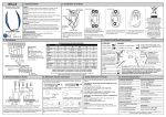
CONNECTIONS ON THE TERMINAL BOARD:
1 – Input 230 Vac line (Phase).
2 – Input 230 Vac line (Neutral).
3 – Input 230 Vac blinking light (Neutral).
4 – Input 230 Vac blinking light (Phase).
5 – Outlet lifting motor.
6 – Outlet common motor.
7 – Outlet lowering motor.
8 : Outlet service power feed at 24 Vac 3 W.
9 : Outlet service power feed at 24 Vac 3 W.
10 : Input open-close control button (NA).
11 : Input common GND.
12 : Input security device (NC).
13 : Input hot pole antenna.
14 : Input ground antenna.
OPERATING CHARACTERISTICS
Step-Step Operation: When a one-channel remote control ( CODE LED for access ) or low-voltage button is used to operate the shutter, the following functional sequence occurs: the first impulse triggers the
opening, up to expiration of the motor time; the second impulse triggers the closing of the shutter. If an impulse is sent before the expiration of the motor time, then the control unit stops the motion; a further command triggers resumption of the motion, but on the opposite direction.
Automatic closing: With the control unit, the shutter can be closed in the automatic mode without sending
any additional commands.The set-up for this mode of operation is described in the paragraph “programming
of the control unit”.
Security device: With the control unit it is possible to power and to connect security devices, such as
photocells, pneumatic slats (NC) etc.. The addition does not result in variations in operation during the
opening phase, while it leads to an inversion of the motion during the closing. If not utilised, this input
must be bridged.
PROGRAMMING OF THE CONTROL UNIT
Programming of the control board is performed using two push buttons, SEL and SET, and warning leds.
The SEL key selects the option to be set; the selection is indicted by the blinking light, which remains active
for 10s, during which time the selection may be modified (see table).At the end of the time period, the control unit returns to the normal mode.The SET key programs the control unit, based on the type of function
selected in advance with the SEL key.
Reference LED
1 – CODE
2 – LAMP.
3 – MOTOR TIME
4 – PAUSE T.
LED off
No code in memory
Blinking light
Infinite time
Without automatic closing
LED on
Code entered
Courtesy light
Programmed time
With automatic closing
1) CODE: (Programming of the remote control)
During the programming procedure, 1 or 2 remote-control codes can be memorised. A single code produces a cyclical movement (Up/Down); using two codes, the upward and downward motion can be controlled separately.
The remote-control transmission codes are programmed as follows:
1 – Push the SEL key.
2 – The CODE LED will start to blink.
3 – Send the first code with the remote control chosen.
4 – The CODE LED shall start to blink rapidly.
5 – Send the second code with the remote control chosen.
14