1
EXH
Explosion-proof housing
EN English - Instructions manual
IT Italiano - Manuale di istruzioni
FR Français - Manuel d'instructions
DE Deutsch - Bedienungslanleitung
RU Русский - Учебник инструкции
EXH
Explosion-proof housing
EN English - Instructions manual
Serial number
Write down the serial number of the product and of any spare part used.
The serial number is given on the label located outside the product packaging and on the metal
mark plate.
jj
Code
Serial Number
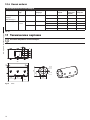
Contents
ENGLISH
1.1 Typographical conventions................................................................................................................................. 5
2 Notes on copyright and information on trademarks................................................. 5
3 Safety rules.................................................................................................................... 5
4 Identification................................................................................................................. 7
4.1 Product description and type designation.................................................................................................... 7
4.1.1 Version for thermal imaging cameras.............................................................................................................................. 7
4.1.2 Version with glass protection device............................................................................................................................... 7
4.2 Product markings.................................................................................................................................................... 8
5 Preparing the product for use...................................................................................... 9
5.1 Safety precautions before use............................................................................................................................ 9
5.2 Contents and unpacking...................................................................................................................................... 9
6 Installing and assembling............................................................................................. 9
6.1 Assembly.................................................................................................................................................................... 9
6.1.1 Range of use............................................................................................................................................................................. 9
6.1.2 Specification of maximum values when installing cameras, including lens..................................................... 9
6.2 Installation...............................................................................................................................................................10
6.2.1 Installing the camera...........................................................................................................................................................10
6.2.2 Changing the back cover gasket.....................................................................................................................................10
6.3 Operational test.....................................................................................................................................................10
7 Instructions for safe operation................................................................................... 11
7.1 Safe operation........................................................................................................................................................11
7.1.1 Commissioning......................................................................................................................................................................11
7.1.2 Safety rules..............................................................................................................................................................................11
7.1.3 Explosion prevention rules................................................................................................................................................11
8 Maintaining and cleaning........................................................................................... 11
8.1 Maintenance and cleaning by users...............................................................................................................11
8.1.1 Routine (to be carried out regularly)..............................................................................................................................11
8.1.2 Extraordinary (to be done only under particular circumstances)........................................................................12
8.2 Spare parts...............................................................................................................................................................12
8.3 Repairs.......................................................................................................................................................................12
9 Disposal of waste materials........................................................................................ 12
10 Technical data............................................................................................................ 13
10.1 General...................................................................................................................................................................13
10.2 Mechanical............................................................................................................................................................13
10.3 Electrical.................................................................................................................................................................13
10.4 Environment.........................................................................................................................................................13
10.5 Certifications.........................................................................................................................................................13
10.6 Cable glands.........................................................................................................................................................14
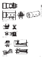
11 Technical drawings.................................................................................................... 14
12 Appendix A - Electrical diagram............................................................................... 16
3
EN - English - Instructions manual
1 About this manual......................................................................................................... 5
EN - English - Instructions manual
13 Appendix B - EXH Declaration.................................................................................. 17
4
3 Safety rules
Before installing and using this unit, please read this
manual carefully. Be sure to keep it handy for later
reference.
hh
The manufacturer declines all responsibility
for any damage caused by an improper use
of the appliances mentioned in this manual.
Furthermore, the manufacturer reserves
the right to modify its contents without any
prior notice. The documentation contained
in this manual has been collected with great
care, the manufacturer, however, cannot
take any liability for its use. The same thing
can be said for any person or company
involved in the creation and production of
this manual.
1.1 Typographical conventions
DANGER!
High level hazard.
Risk of electric shock; disconnect the
power supply before proceeding with any
operation, unless indicated otherwise.
gg
DANGER!
Explosion hazard.
Read carefully to avoid danger of explosion.
oo
This device must be connected to an earth
conductor.
hh
WARNING!
Medium level hazard.
This operation is very important for the
system to function properly. Please read
the procedure described very carefully and
carry it out as instructed.
hh
INFO
Description of system specifications.
We recommend reading this part carefully
in order to understand the subsequent
stages.
jj
2 Notes on copyright and
information on trademarks
The quoted names of products or companies are
trademarks or registered trademarks.
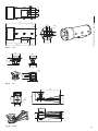
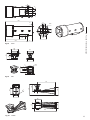
Fig. 01
Earth connection.
• Make sure that all the devices are suitable for the
application and for the environment in which they
will be installed.
• Make sure that the connected devices are
completely compatible and suitable for use.
• Make sure the operating temperatures are
compatible with the devices.
• When installing the devices make sure the system
and installer personnel are absolutely safe.
• Choose an installation site that is strong enough
to sustain the weight of the device, also bearing
in mind particular environmental aspects, such as
exposure to strong winds.
• We strongly recommend using only approved
brackets and accessories during installation.
5
EN - English - Instructions manual
1 About this manual
EN - English - Instructions manual
• Make sure that the device is firmly anchored so
that it cannot become detached.
• Do not allow children or untrained people to use
the device.
• Since the user is responsible for choosing the
surface to which the device is to be anchored,
we do not supply screws for attaching the device
firmly to the particular surface. The installer is
responsible for choosing screws suitable for the
specific purpose on hand.
• The device can only be considered to be switched
off when the power supply has been disconnected
and the connection cables to other devices have
been removed.
• The device must be installed and maintained only
and exclusively by qualified technical personnel.
• Use appropriate tools for the purpose. The
particular nature of the site where the device is to
be installed may mean special tools are required
for installation.
• Make sure that the installation complies with local
regulations and specifications.
• This device must be installed out of the reach of
the user or of anyone who might happen to touch
it by chance.
• Before doing any technical work on the device,
disconnect the power supply.
• Do not use power supply cables that seem worn
or old.
• Only qualified technical personnel should be
allowed to open the device, and they should work
in a non-explosive atmosphere. Tampering with
the device will invalidate the guarantee.
6
• Before powering the device install an overload
protection device in the electrical equipment for
the building.
• The user must not install any apparatus inside the
device if it generates dangerous radiation.
• For technical services, consult only and exclusively
authorised technicians.
• Keep this handbook carefully; it must be available
for consultation on the installation site.
• Never, under any circumstances, make any
changes or connections that are not shown in this
handbook: improper use of the device can cause
serious hazards, risking the safety of personnel and
of the system.
• Use only VIDEOTEC original spare parts.
• Before proceeding with installation check the
supplied material to make sure it corresponds
to the order specification by examining the
identification labels ("4.2 Product markings",
page 8).
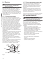
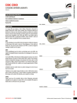
4 Identification
The EXH series explosion-proof housing has been
designed for use with cameras operating in industrial
environments in which there may be an explosive
atmosphere due to gas, vapours, mists, or air or
powder mixtures.
EXH housings comprise solid, cast Anticorodal
aluminium alloy from the AlSi7Mg EN AB-42000
group, the exact chemical composition of which is
defined in the UNI EN 1706 standard.
Depending on the model, all parts are powderpainted and oven-cured or treated with special
coatings giving excellent resistant to UV light, to salt
spray and to atmospheric pollutants.
The camera body comprises a cylindrical tube, with
a flange that houses a strong, transparent glass;
opposite to the glass there is another flange that, as
well as closing the cylinder, also supports the plate to
which the camera is to be attached.
The EXH series of explosion-proof housings has a
version with a glass protection device, installed on
the front opening of the housing. It comprises a
flange for linking with the housing, a closing flange
and a central, explosion-proof body containing a
strong, transparent glass, a 24Vdc motor, two winders
and transparent Mylar film, installed in front of the
glass.
The motor uses 4 bevel gears to pilot a winder for
recovering dirty film, while the other winder issues
clean film. The motor is remotely controlled by a twowire ON-OFF contact (one common and one +24Vac/
Vdc, Fig. 08, page 16).
The control unit for the glass protection
device is supplied by the customer.
hh
The transparent Mylar film can be fed forward about
350 times.
The housing has two holes for 3/4" NPT cable glands.
When the film is dirty the operator starts the motor,
so that the film is fed forward until a clean image is
obtained (to completely replace the dirty film in one
step, about 50mm of clean film should be fed).
The cable glands must be selected according to what
is indicated by the EN/IEC 60079-14 Standard.
The end of the tape is marked by printing on the last
50cm of film.
These cable glands guarantee an IP66 protection
level.
Film feed can also be started automatically by a
timing device if a suitable control system is used (this
is not supplied).
We recommend using VIDEOTEC cable
glands or equivalent (Tab. 01, page 14).
jj
To change the film, see the VIDEOTEC spare part
handbook (code OEXMYLAR).
4.1.1 Version for thermal imaging
cameras
When using thermal imaging cameras, which are able
to detect heat emission, a special filter on the front
of the housing should be used.This housing differs
in that it has a window made mainly of germanium,
which guarantees the same strength and security
properties as those for standard glass. Range of
application from 7.5 to 14µm.
7
EN - English - Instructions manual
4.1 Product description and type
designation
4.1.2 Version with glass protection
device
EN - English - Instructions manual
4.2 Product markings
Check the certifications on the data plate of
the product you have purchased.
hh
04
07. Camera:
• Power supply voltage (V)
• Maximum power consumption (W) - (the data
for the camera refer to the voltage specification
and maximum allowed power consumption for
camera operation)
08. ATEX certification:
01
• ATEX certificate number
02
• Classification for zone type, protection method,
temperature class for which this product may be
used in compliance with the ATEX directive
03
05
• CE mark and number of notified body that
carries out production checks
06
09. IECEx certification:
07
• IECEx certificate number
08
• Classification for zone type, protection method
and temperature class for which this product
may be used in compliance with the IECEx
standard
09
10. EAC certification:
10
• EAC certificate number
11
• Classification for zone type, protection method
and temperature class for which this product
may be used
11. Chinese certification:
• CNEx certificate number
Fig. 02
Example of data plate.
01. CE symbol
02. Manufacturer’s name and address
03. Model identification code
04. Ambient temperature of use referring to
model identification code
05. Serial number
06. Housing:
• Power supply voltage (V)
• Absorption current (A)
• Frequency (Hz)
• Housing power consumption (W)
8
• Classification of the type of area, the protection
method and the temperature range the product
can be used in according to Chinese standards
Before installation, make sure the power
supply and protection specifications of the
device correspond to those in the original
order. Use of unsuitable appliances can
cause serious hazards, risking the safety of
personnel and of the installation.
hh
5 Preparing the product
for use
No special requirements are demanded
from those in charge of handling; therefore
follow normal accident prevention
regulations when carrying out this
operation.
jj
5.1 Safety precautions before
use
The following procedures should be carried
out with the power supply disconnected,
unless indicated otherwise. An appropriate
protection device should be installed in
the electrical equipment upstream of the
device.
gg
Never exceed performance specifications.
Do not replace the housing screws with
other kinds of screw. Make all connections
in a non-explosive atmosphere.
oo
The device must be installed only
and exclusively by qualified technical
personnel. Make connections and tests
in the laboratory before carrying out
installation on site. Use appropriate tools
for the purpose.
hh
5.2 Contents and unpacking
When the product is delivered, make sure that the
package is intact and that there are no signs that it
has been dropped or scratched.
Only specialised personnel should be
allowed to install and assemble the device.
hh
6.1 Assembly
6.1.1 Range of use
The EXH housing is designed for use in a fixed
location, for surveillance of areas with class 1-21 or
class 2-22 potentially explosive atmospheres, using a
camera/lens installed inside the housing by the user.
The EXH housing is made and certified in compliance
with the 94/9/CE ATEX Directive and the IECEx
international Standard, which define the application
field and the minimum safety requirements.
The housings for thermal imaging cameras have been
built and certified in compliance with ATEX directive
94/9/CE, which define the range of application and
minimum safety requirements.
6.1.2 Specification of maximum values
when installing cameras, including lens
The housing and the heating system must
use the same power supply.
gg
The installer should never use devices
that do not remain within the specified
maximum values.
hh
• Camera: Analogue or network camera
• Maximum power: 20W
• Maximum voltage: 240Vac
• Usable volume for camera/lens: 2800cm3
• Minimum distance between the walls of the
housing and the camera/lens: 12mm
If there are obvious signs of damage, contact the
supplier immediately.
Keep the packaging in case you need to send the
product for repairs.
Check the contents to make sure they correspond
with the list of materials as below:
• 1 explosion-proof housing
• 1 gasket kit
• 1 instructions manual
9
EN - English - Instructions manual
Any change that is not expressly approved
by the manufacturer will invalidate both
the guarantee and certification.
hh
6 Installing and
assembling
EN - English - Instructions manual
6.2 Installation
6.2.2 Changing the back cover gasket
The installer must not use devices that
generate dangerous radiation.
hh
The back flange of the housing has 12 stainless
steel A2-type M6 screws. It also has 3 screws at 120°
intervals to facilitate extraction of the flange. When
the M6-thread screws have been unscrewed from
the flange, turning the 3 screws at 120° (one turn per
screw at a time, in turn) will make it easier to extract
the flange.
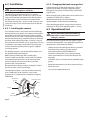
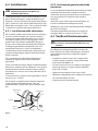
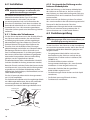
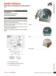
6.2.1 Installing the camera
To install the camera, you have to extract the flange
closing the housing, which also supports the plate to
which the camera will be attached, and the related
terminal board. This plate is supported on two guides
attached to the housing; when the flange is removed,
the plate slides along the guides, so that it is easy to
fit and connect the camera and its accessories. During
installation, we strongly recommend insulating the
camera from the support plate using the supplied
insulating spacers.
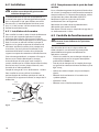
(To identify the parts, see the illustration below and
the attached electrical diagram).
Before closing the flange, after installing the
camera, make sure that the 4 earth wires have been
connected (back cover, front cover, housing body,
terminal board) and make sure they have been
placed at the same potential.
We recommend a torque wrench setting of 12.5Nm
for the 12 screws closing the flange.
The appropriate joint is used to install the housing.
It has 4xM6 holes at 90° intervals, and, where
appropriate, a bracket which is attached using the
4xM8 holes.
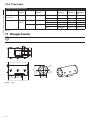
Back cover
gasket
Terminal board
Flange
Earth
connection
Fig. 03
10
Fixing plate
If the back cover gasket of the housing is worn it
should be replaced using the supplied spare or,
failing that, using only and exclusively a VIDEOTEC
original part.
When changing the gasket, take care to make sure it
is properly inserted in its seating.
Reconnect the earth wires that had been
disconnected in order to extract the flange.
Close the flange properly, using a torque wrench
setting of 12.5Nm when tightening the 12 screws.
6.3 Operational test
Before proceeding with the following
operations, make sure that the mains
voltage is correct.
hh
To connect the housing to the main power supply
use cables designed for use in potentially explosive
atmospheres, and proceed as follows:
• Choose and install cable glands that are suitable
for the housing marking and the type of
atmosphere present (EN/IEC60079-14);
• Fasten the cable gland using a torque setting
which guarantees that at least five threads are
engaged;
• Use cables that are suitable for the selected cable
glands;
• Make the connections with the camera and lens;
• Power the unit;
• Carry out the operational tests.
7 Instructions for safe
operation
Before doing any technical work on the
device, disconnect the power supply.
hh
gg
8.1 Maintenance and cleaning
by users
7.1.1 Commissioning
8.1.1 Routine (to be carried out
regularly)
Before proceeding with the following
operations, make sure that the mains
voltage is correct.
• Read the whole of this user’s handbook very
carefully;
• Install the camera and lens correctly;
• Test system operation for positive results;
• Prepare an appropriate power supply line.
7.1.2 Safety rules
• Given the considerable weight of the system, use
an appropriate transport and handling system.
• Before starting any operation, make sure the
power supply is disconnected;
• Before powering the system, install an overload
protection device in the electrical equipment for
the building.
• Make sure that all precautions for personal safety
have been taken;
• Installation of the electrical equipment must
comply with the local legislation in force.
7.1.3 Explosion prevention rules
• Choose a solid, stable support surface;
• Choose an appropriate support bracket, if used;
• Use appropriate tools for the area in which you are
working;
• Do not open the housing if there is a possibility of
your being in a potentially explosive atmosphere.
• Use safe, long-lasting screws or other anchorage
systems.
Always remember that the unit must
be connected to an appropriate earth
conductor.
oo
• Cleaning the glass: Water should be used, or a
liquid detergent that will not generate a hazardous
situation;
• Cleaning the germanium window: Use neutral
soap diluted with water; take extra care not to
scratch or damage the outer surface treated with
carbon coating. Damage to this coating could also
interfere with the transparency of the surface to
infrared light. Do not use ethyl alcohol , solvents,
hydrogenated hydrocarbons, strong acids or
alkalis. Using these products will irreparably
damage the germanium surface.
• Cleaning the device: This should be done
regularly; if a layer of dust accumulates on the
outside of the housing, it should never be more
than 5mm thick. The device should be cleaned
using a damp cloth; compressed air must not be
used. Maintenance frequency will depend on the
type of environment in which the housing is used.
• Inspecting the cables: The cables should not
show signs of damage or wear, which could
generate hazardous situations; in this case
extraordinary maintenance is necessary.
• Changing the Mylar tape (version with glass
protection device): To carry out this operation,
the minimum safety conditions indicated in "7
Instructions for safe operation", page 11 must be
ensured. To proceed, loosen the 4 fixing screws on
the glass protection cover, then simply remove the
rollers with the dirty belt and replace them with
the rollers with clean belt.
After commissioning the system keep this
handbook in a safe place, available for later
consultation.
hh
11
EN - English - Instructions manual
7.1 Safe operation
8 Maintaining and cleaning
EN - English - Instructions manual
• Opening the housing to change the camera:
Check the condition of the back cover gasket of
the housing; if it needs changing use only the one
supplied with the housing or, failing that, use only
VIDEOTEC original spare parts ("6.2.2 Changing the
back cover gasket", page 10).
8.2 Spare parts
To order the spare parts it is necessary to
provide the serial number of the product on
which the intervention is to be carried out
([email protected]).
jj
8.1.2 Extraordinary (to be done only
under particular circumstances)
8.3 Repairs
• Changing the front unit with glass (or the glass
protection unit when present).
jj
• Changing the inner slide unit with heater wiring
and electrical connection board, using the
appropriate spare part for versions with or without
the glass protection device.
• Hazardous wear or damage to cables.
• Camera or lens failure.
• Explosion in or near the housing.
• Any other situation in which the housing has to be
opened.
For damage to any parts that are not
indicated above, repair or replacement
must be done by VIDEOTEC.
hh
Whenever replacing the parts as indicated,
always use VIDEOTEC original spare parts
and meticulously follow the maintenance
instructions supplied with every spare parts
kit.
hh
The manufacturer declines all liability for
damage to any of the apparatus mentioned
in this handbook, when resulting from
tampering, use of non-original spare parts,
and from installation and maintenance/
repairs performed by non-authorised, nonskilled personnel.
hh
In all such circumstances, the housing
should be sent to the workshop for the
necessary repairs or maintenance.
jj
12
For any other maintenance intervention the
product must be sent to VIDEOTEC, subject
to a request for return authorisation
([email protected]).
9 Disposal of waste
materials
This symbol mark and recycle system
are applied only to EU countries and not
applied to the countries in the other area of
the world.
nn
Your product is designed and manufactured with
high quality materials and components which can be
recycled and reused.
This symbol means that electrical and electronic
equipment, at their end-of-life, should be disposed of
separately from your household waste.
Please dispose of this equipment at your local
Community waste collection or Recycling centre.
In the European Union there are separate collection
systems for used electrical and electronic products.
10 Technical data
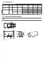
10.3 Electrical
10.1 General
Heater Ton 15°C +/-4°C Toff 22°C +/-3°C
Non-corrosive die-cast aluminium (anticorodal)
IN 230Vac, consumption 20W max (only for EXH200)
Bicomponent polyurethane enamel with orange peel
effect, RAL7032
Reinforced heater Ton 15°C +/-4°C Toff 22°C +/-3°C
Special painting, blue colour RAL7001. Resistant to stress
cracking, adverse weather conditions, detergents, saltspray and typical airborne pollutants
EN - English - Instructions manual
IN 24Vac, consumption 20W max
IN 24Vac, consumption 20W max
3 resistors in the housing, consumption 60W max
Glass protection device
10.2 Mechanical
24Vac, consumption 2W max
2 holes for cable glands 3/4" NPT
Camera: Analogue or network camera
External dimensions
Camera equipped with lens with maximum total power:
20W
Devices to install inside the housing
EXHC
Ø 210mmx427.5mm
(8.2x16.8in)
EXHD
Ø 250x573.5mm (9.8x 22.6in)
Usable volume for camera/lens: 2800cm3
EXHC
Ø 180x380mm (7x14.9in)
Minimum distance between the walls of the housing and
the camera/lens: 12mm
EXHD
Ø 180x460mm (7x 18.1in)
Internal dimensions
Internal usable area
EXHC100x100x280mm
(3.9x3.9x11in)
EXHD100x100x280mm
(3.9x3.9x11in)
Glass window
EXHC
Ø 114mm (4.5in)
EXHD
70x56mm (2.7x2.2in)
Device for the protection of the glass
Device for the protection of the glass Ø 250x140mm
Mylar film 80mm (3.1in) wide and 18m (59ft) length, 350
shifting steps, marks printed on the last 50cm (19in)
Wall mount
Load rating: 35kg (77lb)
Length: 455mm (17.9in)
Parapet mount
Load rating: 35kg (77lb)
Maximum voltage: 240Vac (24Vac or 230Vac versions)
10.4 Environment
Operating temperature with heater: -20°C / +50°C
Operating temperature with reinforced heater:
-40°C / +50°C
Always refer to the temperature in the marking
10.5 Certifications
ATEX (EN 60079-0: 2009, EN 60079-1: 2007, EN 60079-31:
2009):
-- b II 2G Ex d IIC T6 Gb
-- b II 2D Ex t IIIC T85 °C Db IP66
-- c 0044: notify number from competent body
IECEx (IEC 60079-0: 2007, IEC 60079-1: 2007, IEC 6007931: 2008):
-- Ex d IIC T6 Gb
-- Ex t IIIC T85 °C Db IP66
EAC EX:
-- Ex d IIC T6 Gb
-- Ex tb IIIC T85 Db X IP66
CNEX:
-- Ex d IIC T6 Gb
-- DIP A21 TA T6
-- Tamb: -20+50°C
-- Tamb: -40+50°C (when equipped with reinforced
heater)
For each version, verify the existing certification.
13
10.6 Cable glands
Certification
Operating
temperature
IIC Zone 1 or Zone 2
IIB or IIA Zone 1
Barrier
IECEX / ATEX
-60 / +80°C
-76 / 176°F
Not armored
OCTEXB3/4C
13 - 20.2
-
Armored
OCTEXBA3/4C
16.9 - 26
-
IIB or IIA Zone 2
With gasket IECEX / ATEX
-60 / +100°C
-76 / 212°F
Not armored
OCTEX3/4C
13 - 20.2
-
Armored
OCTEXA3/4C
16.9 - 26
11.1 - 19.7
-20 / +80°C
-4 / 176°F
Not armored
OCTEX3/4
14 - 17
-
Armored
OCTEXA3/4
18 - 23
14 - 17
ATEX
Cable
Cable glands
part code
External
Diameter
diameter (mm) under armour
(mm)
Cable
gland type
Tab. 01
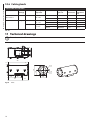
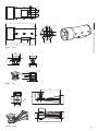
11 Technical drawings
The values are in millimeters.
jj
50
41
30
41
428
12
12
220
Ø 210
Ø 114
115
EN - English - Instructions manual
CABLE GLANDS SELECTION TABLE
Zone - Gas
147
130
312
Fig. 04
14
EXHC
132
116
41
30
41
50
EN - English - Instructions manual
574
70
Ø 250
56
12
293
132
130
458
Fig. 05
116
EXHD
150
125
142
98
44
8
125
Ø 135
125
33
30
16
Ø 6.4
16
Fig. 06
93
16
EXBJ
150
170
1
Ø1
233
142
390
110
144
125
125
458
Fig. 07
EXWBJ
15
EN - English - Instructions manual
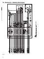
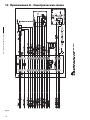
12 Appendix A - Electrical diagram
Fig. 08
16
13 Appendix B - EXH Declaration
EN - English - Instructions manual
17
VIDEOTEC S.p.A.
www.videotec.com
Printed in Italy
MNVCEXH_1511_EN
EXH
Custodia antideflagrante
IT Italiano - Manuale di istruzioni
Numero seriale
Trascrivere il numero di serie del prodotto e degli eventuali ricambi utilizzati.
Il numero seriale è riportato nell'etichetta presente all'esterno dell'imballo del prodotto e sulla
targhetta metallica di marcatura.
jj
Codice
Numero seriale
Sommario
ITALIANO
1 Informazioni sul presente manuale............................................................................. 5
1.1 Convenzioni tipografiche..................................................................................................................................... 5
4.1 Descrizione e designazione del prodotto...................................................................................................... 7
4.1.1 Versione per telecamere termiche.................................................................................................................................... 7
4.1.2 Versione con dispositivo protezione vetro.................................................................................................................... 7
4.2 Marcatura del prodotto......................................................................................................................................... 8
5 Preparazione del prodotto per l'utilizzo..................................................................... 9
5.1 Precauzioni di sicurezza prima dell'utilizzo................................................................................................... 9
5.2 Contenuto e disimballaggio................................................................................................................................ 9
6 Installazione e assemblaggio....................................................................................... 9
6.1 Assemblaggio........................................................................................................................................................... 9
6.1.1 Campo di utilizzo..................................................................................................................................................................... 9
6.1.2 Specifiche massime delle telecamere comprese di ottica installabili.................................................................. 9
6.2 Installazione............................................................................................................................................................10
6.2.1 Installazione della telecamera..........................................................................................................................................10
6.2.2 Sostituzione guarnizione fondo posteriore.................................................................................................................10
6.3 Verifica di funzionamento..................................................................................................................................10
7 Istruzioni di funzionamento in sicurezza.................................................................. 11
7.1 Funzionamento in condizioni di sicurezza...................................................................................................11
7.1.1 Messa in servizio....................................................................................................................................................................11
7.1.2 Prescrizioni di sicurezza......................................................................................................................................................11
7.1.3 Prescrizioni di prevenzione di esplosione....................................................................................................................11
8 Manutenzione e pulizia.............................................................................................. 11
8.1 Manutenzione e pulizia da parte degli utilizzatori....................................................................................11
8.1.1 Ordinaria (da eseguire periodicamente).......................................................................................................................11
8.1.2 Straordinaria (da eseguire solo in casi particolari)....................................................................................................12
8.2 Ricambi.....................................................................................................................................................................12
8.3 Riparazioni...............................................................................................................................................................12
9 Smaltimento dei rifiuti................................................................................................ 12
10 Dati tecnici................................................................................................................. 13
10.1 Generale.................................................................................................................................................................13
10.2 Meccanica..............................................................................................................................................................13
10.3 Elettrico..................................................................................................................................................................13
10.4 Ambiente...............................................................................................................................................................13
10.5 Certificazioni.........................................................................................................................................................13
10.6 Pressacavi...............................................................................................................................................................14
11 Disegni tecnici........................................................................................................... 14
12 Appendice A - Schema elettrico............................................................................... 16
3
IT - Italiano - Manuale di istruzioni
2 Note sul copyright e informazioni sui marchi commerciali....................................... 5
3 Norme di sicurezza........................................................................................................ 5
4 Identificazione............................................................................................................... 7
IT - Italiano - Manuale di istruzioni
13 Appendice B - Dichiarazione EXH............................................................................ 17
4
1 Informazioni sul presente
manuale
Il produttore declina ogni responsabilità
per eventuali danni derivanti da un
uso improprio delle apparecchiature
menzionate in questo manuale. Si
riserva inoltre il diritto di modificarne il
contenuto senza preavviso. Ogni cura é
stata posta nella raccolta e nella verifica
della documentazione contenuta in questo
manuale, tuttavia il produttore non può
assumersi alcuna responsabilità derivante
dall’utilizzo della stessa. Lo stesso dicasi
per ogni persona o società coinvolta nella
creazione e nella produzione di questo
manuale.
hh
1.1 Convenzioni tipografiche
PERICOLO!
Pericolosità elevata.
Rischio di scosse elettriche. Togliere
l'alimentazione prima di procedere con le
operazioni, salvo diversa indicazione.
gg
PERICOLO!
Pericolo di esplosione.
Leggere attentamente per evitare pericoli
di esplosione.
oo
Questo dispositivo deve essere collegato a
terra.
hh
ATTENZIONE!
Pericolosità media.
L'operazione è molto importante per il
corretto funzionamento del sistema. Si
prega di leggere attentamente la procedura
indicata e di eseguirla secondo le modalità
previste.
hh
INFO
Descrizione delle caratteristiche del
sistema.
Si consiglia di leggere attentamente per
comprendere le fasi successive.
jj
2 Note sul copyright e
informazioni sui marchi
commerciali
I nomi di prodotto o di aziende citati sono marchi
commerciali o marchi commerciali registrati
appartenenti alle rispettive società.
Fig. 01
Messa a terra.
• Assicurarsi che tutti i dispositivi siano adatti per
l’applicazione e l’ambiente per cui sono stati
progettati.
• Assicurarsi che i dispositivi collegati siano
completamente compatibili e adatti all’uso.
• Controllare che le temperature di esercizio siano
compatibili con i dispositivi.
• Accertarsi di installare i dispositivi in maniera
tale da garantire la sicurezza dell’impianto e del
personale addetto all’installazione.
• Scegliere la postazione di installazione in modo
che sia sufficientemente solida da sostenere il
peso del dispositivo, considerando anche aspetti
ambientali particolari come esposizione a vento
forte.
• Si raccomanda di utilizzare solo staffe o accessori
consigliate per l’installazione.
5
IT - Italiano - Manuale di istruzioni
Prima di installare e utilizzare questa unità, leggere
attentamente questo manuale. Conservare questo
manuale a portata di mano come riferimento futuro.
3 Norme di sicurezza
IT - Italiano - Manuale di istruzioni
• Accertarsi che il dispositivo sia fissato in maniera
solida ed affidabile.
• Non permettere l’uso dell’apparecchio a bambini
o incapaci.
• Dato che la scelta della superficie di montaggio
è a cura dell’utente non si forniscono viti per il
fissaggio sicuro del dispositivo alla superficie. È
responsabilità dell’installatore utilizzare viti adatte
allo scopo specifico richiesto.
• L’apparecchio si considera disattivato soltanto
quando l’alimentazione é disinserita e i cavi di
collegamento con altri dispositivi sono stati
rimossi.
• L’installazione e la manutenzione del dispositivo
deve essere eseguita solo da personale tecnico
qualificato.
• Utilizzare degli utensili adeguati. Degli utensili
specifici possono essere richiesti, per motivi
di installazione, in relazione al luogo in cui il
dispositivo viene installato.
• Assicurarsi che l’installazione soddisfi le specifiche
locali.
• Questo dispositivo deve essere installato fuori dalla
portata dell’utente o di chiunque ne possa entrare
a contatto casualmente.
• Prima di effettuare interventi tecnici
sull’apparecchio togliere l’alimentazione elettrica.
• Non utilizzare cavi di alimentazione con segni di
usura o invecchiamento.
• L’apparecchio deve essere aperto soltanto da
personale tecnico qualificato e in atmosfera non
esplosiva. La manomissione dell’apparecchio fa
decadere i termini di garanzia.
6
• Prima dell’alimentazione del dispositivo installare
un dispositivo di protezione nell’impianto elettrico
dell’edificio.
• Si raccomanda all’utente di non installare
all’interno del dispositivo qualsiasi apparecchiatura
che generi radiazioni pericolose.
• Per l’assistenza tecnica rivolgersi esclusivamente al
personale tecnico autorizzato.
• Conservare con cura il presente manuale; deve
essere a disposizione per eventuali consultazioni
nel luogo in cui viene eseguita l’installazione.
• Non effettuare per nessun motivo alterazioni o
collegamenti non previsti in questo manuale:
l’uso di apparecchi non idonei può portare a
gravi pericoli per la sicurezza del personale e
dell’impianto.
• Utilizzare solo parti di ricambio VIDEOTEC.
• Prima di procedere con l'installazione controllare
che il materiale fornito corrisponda alle specifiche
richieste esaminando le etichette di marcatura ("4.2
Marcatura del prodotto", pagina 8).
4 Identificazione
4.1 Descrizione e designazione
del prodotto
Le custodie EXH sono realizzate in massiccia fusione
in lega di alluminio Anticorodal del gruppo AlSi7Mg
EN AB-42000 la cui composizione chimica è definita
dalla norma UNI EN 1706.
Secondo il modello, tutti gli elementi sono verniciati
con polveri in forno o trattati con particolari
rivestimenti che offrono un’eccellente resistenza ai
raggi ultravioletti, alla nebbia salina e agli agenti
inquinanti presenti nell’atmosfera.
II corpo camera è costituito da un tubo cilindrico,
dotato di flangia che alloggia un robusto vetro
trasparente; dalla parte opposta al vetro é presente
un’ulteriore flangia che, oltre a chiudere il cilindro,
sostiene la piastra per il fissaggio della telecamera.
La custodia presenta due fori per pressacavi 3/4" NPT.
La scelta del pressacavo deve essere fatta secondo
quanto previsto dalla norma EN/IEC 60079-14.
Tali pressacavi assicureranno il grado di protezione
IP66.
Si consiglia l'utilizzo di pressacavi
VIDEOTEC o equivalenti (Tab. 01,
pagina 14).
jj
4.1.1 Versione per telecamere termiche
Esiste una versione di custodia antideflagranti
della serie EXH con dispositivo di protezione vetro,
installato sull’apertura frontale della custodia.
Esso è costituito da una flangia di raccordo con
la custodia, una flangia di chiusura e da un corpo
centrale antideflagrante contenente un robusto
vetro trasparente, un motore in corrente continua
alimentato a 24Vdc, due avvolgitori ed una pellicola
trasparente in Mylar, installata di fronte al vetro.
Il motore, attraverso 4 pignoni conici dentati, pilota
un avvolgitore per il recupero della pellicola sporca,
mentre l’altro avvolgitore rilascia la pellicola pulita.
Il motore è controllato remotamente tramite un
contatto ON-OFF a due fili (un comune ed un +24Vac/
Vdc, Fig. 08, pagina 16).
L’unità di controllo del dispositivo
protezione vetro è fornita dal cliente.
hh
La pellicola di Mylar trasparente consente circa 350
passi di avanzamento.
Infatti quando è sporca l’operatore attiverà il motore,
facendo avanzare la pellicola sino ad ottenere
un’immagine pulita (il passo per consentire lo
scorrimento completo della pellicola sporca è di circa
50mm).
La fine del nastro viene segnalata mediante
contrassegni stampati sugli ultimi 50cm di pellicola.
L’avanzamento della pellicola potrà avvenire anche
automaticamente in maniera temporizzata tramite
un opportuno sistema di controllo (escluso dalla
fornitura).
Per sostituire la pellicola fare riferimento al manuale
d'uso del ricambio VIDEOTEC (codice OEXMYLAR).
L’impiego di telecamere termiche, in grado di rilevare
l’emissione di calore, richiede l’utilizzo di uno speciale
filtro sul frontale della custodia. Questa custodia si
differenzia per la presenza di una finestra composta
in prevalenza da Germanio; esso garantisce le stesse
caratteristiche di resistenza e di sicurezza del vetro
standard. Campo di applicazione da 7.5 a 14µm.
7
IT - Italiano - Manuale di istruzioni
La custodia antideflagrante della serie EXH è stata
progettata per consentire l’utilizzo di telecamere
operanti in ambienti industriali in cui vi è la
probabilità che si manifestino atmosfere esplosive
dovute a gas, vapori, nebbie o miscele di aria o
polveri.
4.1.2 Versione con dispositivo
protezione vetro
4.2 Marcatura del prodotto
Verificare le certificazioni nella targhetta
del prodotto acquistato.
hh
IT - Italiano - Manuale di istruzioni
04
07. Telecamera:
• Tensione d’alimentazione (V)
• Consumo massimo (W) – (i dati riportati per la
telecamera si riferiscono alle caratteristiche di
tensione e consumo massimo ammesso per il
funzionamento della stessa)
08. Certificazione ATEX:
01
• Numero del certificato ATEX
02
• Classificazione del tipo di zona, metodo di
protezione, classe di temperatura per le quali è
ammesso l’impiego di questo prodotto secondo
la direttiva ATEX
03
05
06
• Marcatura CE e numero dell’organismo
notificato che effettua il controllo sulla
produzione
07
09. Certificazione IECEx:
08
• Numero del certificato IECEx
09
• Classificazione del tipo di zona, metodo di
protezione e classe di temperatura per le quali è
ammesso l’impiego di questo prodotto secondo
la normativa IECEx
10
10. Certificazione EAC:
11
• Numero del certificato EAC
• Classificazione del tipo di zona, metodo di
protezione e classe di temperatura per le quali è
ammesso l’impiego di questo prodotto
11. Certificazione cinese:
Fig. 02
Esempio di targa.
01. Simbolo CE
02. Nome e indirizzo del costruttore
03. Codice di identificazione del modello
04. Temperatura ambiente di utilizzo riferita al
codice di identificazione del modello
05. Numero di serie
06. Custodia:
• Tensione d’alimentazione (V)
• Corrente assorbita (A)
• Frequenza (Hz)
• Consumo custodia (W)
8
• Numero del certificato CNEx
• Classificazione del tipo di zona, metodo di
protezione e classe di temperatura per le quali è
ammesso l’impiego di questo prodotto secondo
gli standard cinesi
Prima dell’installazione controllare se
le caratteristiche di alimentazione e
protezione del dispositivo corrispondono
a quelle richieste. L’uso di apparecchi non
idonei può portare a gravi pericoli per la
sicurezza del personale e dell’impianto.
hh
5 Preparazione del
prodotto per l'utilizzo
Per la movimentazione non sono richiesti
particolari requisiti da parte del personale
addetto, pertanto, si raccomanda di
effettuare tale operazione osservando le
comuni norme di antinfortunistica.
jj
5.1 Precauzioni di sicurezza
prima dell'utilizzo
Le seguenti procedure sono da effettuare
in assenza di alimentazione, se non
diversamente indicato. Un dispositivo
di protezione adeguato deve essere
installato nell’impianto elettrico prima del
dispositivo.
gg
Non superare le prestazioni specificate. Non
sostituire le viti della custodia con altre di
tipo diverso. Eseguire tutte le connessioni
in atmosfera non esplosiva.
oo
La fase di installazione deve essere
effettuata solo da personale tecnico
qualificato. Effettuare i collegamenti e
prove in laboratorio prima dell’installazione
nel sito. Utilizzare degli utensili adeguati.
hh
5.2 Contenuto e disimballaggio
L’installazione e l’assemblaggio vanno
eseguiti solo da personale specializzato.
hh
IT - Italiano - Manuale di istruzioni
Qualsiasi cambiamento non espressamente
approvato dal costruttore fa decadere la
garanzia e la certificazione.
hh
6 Installazione e
assemblaggio
6.1 Assemblaggio
6.1.1 Campo di utilizzo
L’impiego della custodia EXH è definito per l’utilizzo
in postazione fissa per la sorveglianza di zone con
atmosfera potenzialmente esplosiva classificate
1-21 o 2-22, mediante telecamera/ottica installata
dall’utente al suo interno.
La custodia EXH è costruita e certificata in accordo
con la direttiva 94/9/CE ATEX e allo standard
internazionale IECEx, che ne definiscono il campo di
applicazione ed i requisti minimi di sicurezza.
Le custodie per telecamere termiche sono costruite
e certificate in accordo con la direttiva 94/9/CE ATEX,
che ne definisce il campo di applicazione ed i requisiti
minimi di sicurezza.
6.1.2 Specifiche massime delle
telecamere comprese di ottica
installabili
L’alimentazione della custodia deve
essere la stessa utilizzata per il sistema di
riscaldamento.
gg
Si raccomanda all’installatore di non
utilizzare dispositivi che eccedano dalle
specifiche.
hh
• Telecamera: Analogica o network camera
Alla consegna del prodotto verificare che l’imballo
sia integro e non abbia segni evidenti di cadute o
abrasioni.
• Potenza massima: 20W
In caso di evidenti segni di danno all’imballo
contattare immediatamente il fornitore.
• Distanza minima tra le pareti della custodia e la
telecamera/ottica: 12mm
Conservare l’imballo nel caso sia necessario inviare il
prodotto in riparazione.
• Tensione massima: 240Vac
• Volume utile per telecamera/ottica: 2800cm3
Controllare che il contenuto sia rispondente alla lista
del materiale sotto indicata:
• 1 custodia antideflagrante
• 1 dotazione guarnizioni
• 1 manuale di istruzioni
9
6.2 Installazione
Si raccomanda all’installatore di non
utilizzare dispositivi che generino
radiazioni pericolose.
IT - Italiano - Manuale di istruzioni
hh
La flangia posteriore sulla custodia è dotata di 12 viti
M6 in acciaio inox tipo A2. Inoltre è dotata di 3 viti
disposte a 120° per facilitare l’estrazione della flangia
stessa. Infatti una volta svitate dalla flangia le viti con
filetto M6, avvitando le 3 viti a 120° (un giro alla volta,
a rotazione) si agevola l’estrazione della stessa.
6.2.1 Installazione della telecamera
6.2.2 Sostituzione guarnizione fondo
posteriore
In caso di deterioramento della guarnizione presente
nel fondo posteriore della custodia sostituirla
utilizzando solo la guarnizione fornita in dotazione
o in mancanza di essa utilizzare solo ricambio
VIDEOTEC.
Sostituire la guarnizione prestando attenzione ad
inserirla correttamente nell’apposita sede.
Ricollegare i cavi di terra precedentemente scollegati
per estrarre la flangia.
Chiudere correttamente la flangia con coppia di
serraggio delle 12 viti di chiusura pari a 12.5Nm.
Per installare la telecamera occorre estrarre la flangia
di chiusura della custodia, che supporta anche la
piastra di fissaggio della telecamera con la relativa
morsettiera. Questa piastra é appoggiata su due
guide fissate alla custodia; togliendo la flangia la
piastra scorre sulle guide, consentendo di montare
e collegare agevolmente la telecamera ed i suoi
componenti accessori. In fase di installazione si
raccomanda di isolare la telecamera dalla piastra di
supporto utilizzando gli appositi distanziali isolanti
forniti a corredo.
Per effettuare il collegamento della custodia alla
linea utilizzare cavi adatti all’impiego in atmosfere
potenzialmente esplosive, eseguire le seguenti
operazioni:
(Per i particolari fare riferimento all’immagine
riportata di seguito e allo schema elettrico in
appendice).
• Scegliere e installare i pressacavi adeguati alla
marcatura della custodia e al tipo di atmosfera
presente (EN/IEC60079-14);
Prima di chiudere la flangia, dopo l'installazione della
telecamera, verificare di aver collegato i 4 cavi di terra
(fondo posteriore, fondo anteriore, corpo custodia,
morsettiera) e assicurarsi che siamo posti allo stesso
potenziale.
• Fissare il pressacavo con una coppia di serraggio
tale da garantire un numero minimo di filetti in
presa pari a cinque;
Si raccomanda una coppia di serraggio delle 12 viti di
chiusura pari a 12.5Nm.
Per installare la custodia viene utilizzato l’apposito
snodo, dotato di 4 fori M6 disposti a 90°, ed
eventualmente la staffa, che si fissa mediante 4 fori
M8.
Guarnizione
fondo
Morsettiera
Flangia
Messa
a terra
Fig. 03
10
Piastra di fissaggio
6.3 Verifica di funzionamento
Prima di effettuare le seguenti operazioni
assicurarsi che la tensione della linea sia
corretta.
hh
• Utilizzare cavi adeguati ai pressacavi scelti;
• Effettuare i collegamenti con la telecamera e ottica;
• Dare alimentazione all’unità;
• Eseguire prove di funzionamento.
7 Istruzioni di
funzionamento in sicurezza
Prima di effettuare interventi tecnici
sull’apparecchio togliere l’alimentazione
elettrica.
hh
gg
8.1 Manutenzione e pulizia da
parte degli utilizzatori
7.1.1 Messa in servizio
8.1.1 Ordinaria (da eseguire
periodicamente)
Prima di effettuare le seguenti operazioni
assicurarsi che la tensione della linea sia
corretta.
• Leggere attentamente e completamente il
presente manuale d’uso;
• Installare correttamente la telecamera e ottica;
• Controllare il funzionamento del sistema con esito
positivo;
• Predisporre una linea di alimentazione adeguata.
7.1.2 Prescrizioni di sicurezza
• Dato il peso considerevole del sistema è necessario
utilizzare un adeguato sistema di trasporto e
movimentazione;
• Assicurarsi di avere scollegato l’alimentazione
prima di eseguire qualsiasi operazione;
• Prima dell’alimentazione del sistema, installare un
dispositivo di protezione nell’impianto elettrico
dell’edificio;
• Assicurarsi di aver preso tutte le prescrizioni di
sicurezza riguardo l’incolumità del personale;
• L’installazione elettrica dell’impianto deve essere
conforme alle norme locali vigenti.
7.1.3 Prescrizioni di prevenzione di
esplosione
• Scegliere una superficie di appoggio solida e
stabile;
• Scegliere una adeguata staffa di sostegno, se
utilizzata;
• Utilizzare utensili idonei alla zona in cui si opera;
• Non aprire la custodia se vi è la possibilità di
presenza di atmosfera potenzialmente esplosiva;
• Utilizzare viti o altri sistemi di fissaggio sicuri e
duraturi.
• Pulizia del vetro: Deve essere fatta con acqua o
con altro liquido detergente che non crei situazioni
di pericolo.
• Pulizia finestra Germanio: Deve essere
fatta con sapone neutro diluito con acqua;
prestare attenzione a non graffiare o rigare la
superficie esterna trattata con carbon coating.
Danneggiando tale rivestimento c'è il rischio di
compromettere la trasparenza all’infrarosso della
superficie. Sono da evitare alcool etilico, solventi,
idrocarburi idrogenati, acidi forti e alcali. L’utilizzo
di detti prodotti danneggia in modo irreparabile la
superficie del germanio.
• Pulizia dell’apparecchio: Deve essere eseguita
periodicamente; non ci deve essere mai depositato
nella custodia un accumulo di polvere superiore
ai 5mm sulla superficie esterna. La pulizia deve
essere effettuata con un panno umido e senza
l’utilizzo di aria compressa. La frequenza di
interventi di manutenzione dipende dalla tipologia
dell’ambiente in cui è utilizzata la custodia.
• Controllo dei cavi: I cavi non devono presentare
segni di usura o deterioramento tali da creare
situazioni di pericolo, in questo caso si deve
eseguire una manutenzione straordinaria.
• Sostituzione del nastro in Mylar (versione con
dispositivo di protezione vetro): Deve essere
eseguita nelle minime condizioni di sicurezza
indicate nel "7 Istruzioni di funzionamento in
sicurezza", pagina 11. È possibile eseguire questa
operazione svitando le 4 viti di fissaggio del
coperchio della protezione vetro per sostituire i
rullini con il nastro sporco con quelli con il nastro
pulito con un semplice sfilamento.
Si ricorda che l’unità deve essere collegata
ad una connessione di terra elettrica
adeguata.
oo
Dopo la messa in servizio archiviare il
presente manuale d’uso per consultazioni
successive.
hh
11
IT - Italiano - Manuale di istruzioni
7.1 Funzionamento in condizioni
di sicurezza
8 Manutenzione e pulizia
IT - Italiano - Manuale di istruzioni
• Apertura custodia per sostituzione
telecamera: Verificare le condizioni della
guarnizione presente nel fondo posteriore; nel
caso sia necessaria la sostituzione utilizzare solo
quella fornita in dotazione alla custodia o in
mancanza di essa utilizzare solo ricambi VIDEOTEC
("6.2.2 Sostituzione guarnizione fondo posteriore",
pagina 10).
8.1.2 Straordinaria (da eseguire solo in
casi particolari)
• Sostituzione del gruppo frontale munito di vetro
(o gruppo di protezione vetro nelle versioni dove
previsto).
• Sostituzione del gruppo slitta interna munita di
cablaggio per il riscaldamento e scheda elettrica
di collegamento, con l’opportuno ricambio nelle
versioni con o senza il dispositivo di protezione
vetro.
• Usura e deterioramenti pericolosi del cavo.
• Non funzionamento della telecamera o dell’ottica.
• Deflagrazione dentro o nelle vicinanze della
custodia.
• Qualsiasi altra circostanza che implica l’apertura
della custodia.
In caso di danneggiamento la sostituzione
o riparazione di altre parti interessate oltre
a quelle indicate, deve essere eseguita da
VIDEOTEC.
hh
Qualsiasi sostituzione dei particolari
indicati deve essere eseguita utilizzando
solamente ricambi originali VIDEOTEC
seguendo scrupolosamente le istruzioni
di manutenzione allegate ad ogni kit di
ricambio.
hh
Il costruttore declina ogni responsabilità
per eventuali danni derivanti da
manomissione, utilizzo di ricambi non
originali, installazioni e manutenzione/
riparazioni eseguite da personale non
preparato, di tutte le apparecchiature
menzionate in questo manuale.
hh
Si consiglia, per tutti questi casi di riportare
in laboratorio la custodia per effettuare le
operazioni necessarie.
jj
12
8.2 Ricambi
È necessario comunicare il numero di serie
del prodotto sul quale avverrà l’intervento,
per poter ordinare i ricambi stessi
([email protected]).
jj
8.3 Riparazioni
Per qualsiasi altro intervento di
manutenzione il prodotto deve essere
inviata a VIDEOTEC, previa richiesta di
autorizzazione al reso
([email protected]).
jj
9 Smaltimento dei rifiuti
Questo simbolo e il sistema di riciclaggio
sono validi solo nei paesi dell'EU e non
trovano applicazione in altri paesi del
mondo.
nn
Il vostro prodotto è stato costruito da materiali e
componenti di alta qualità, che sono riutilizzabili o
riciclabili.
Prodotti elettrici ed elettronici che portano questo
simbolo alla fine dell'uso devono essere smaltiti
separatamente dai rifiuti casalinghi.
Vi preghiamo di smaltire questo apparecchio in un
Centro di raccolta o in un'Ecostazione.
Nell'Unione Europea esistono sistemi di raccolta
differenziata per prodotti elettrici ed elettronici.
10 Dati tecnici
10.3 Elettrico
10.1 Generale
Riscaldamento Ton 15°C +/-4°C Toff 22°C +/-3°C
Fusione di alluminio anticorodal
IN 230Vac, consumo 20W max (solo per EXH200)
Smalto puliuretanico bicomponente ad effetto bucciato
RAL7032
Riscaldamento rinforzato Ton 15°C +/-4°C Toff 22°C
+/-3°C
Verniciatura speciale, colore azzurro RAL7001. Resistente
alle sollecitazioni di rottura, a condizioni atmosferiche
sfavorevoli, ai detergenti, alla nebbia salina e agli agenti
inquinanti tipici presenti nell’atmosfera
IN 24Vac, consumo 20W max
10.2 Meccanica
24Vac, consumo 2W max
2 fori per pressacavi 3/4" NPT
Telecamera: Analogica o network camera
Dimensioni Esterne
IN 24Vac, consumo 20W max
Dispositivo pulizia vetro
Dispositivi installabili all’interno della custodia
EXHC
Ø 210x427.5mm
Telecamere munite di ottica con potenza massima
complessiva: 20W
EXHD
Ø 250x573.5mm
Tensione massima: 240Vac (versioni 24Vac o 230Vac)
Volume utile per telecamera/ottica: 2800cm3
Dimensioni Interne
EXHC
Ø 180x380mm
EXHD
Ø 180x460mm
Area Utile Telecamera
EXHC100x100x280mm
EXHD100x100x280mm
Finestra in vetro
EXHC
Ø 114mm
EXHD70x56mm
Dispositivo pulizia vetro
Dispositivo protezione vetro Ø 250x140mm
Pellicola in Mylar, larga 80mm e lunga 18m che consente
circa 350 passi di avanzamento, munito di contrassegno
sugli ultimi 50cm
Supporto da parete
Portata: 35kg
Lunghezza: 455mm
Supporto a colonna
Portata: 35kg
IT - Italiano - Manuale di istruzioni
3 resistenze nella custodia, consumo totale 60W max
Distanza minima tra le pareti della custodia e la
telecamera/ottica: 12mm
10.4 Ambiente
Temperatura d’esercizio con riscaldamento: -20°C / +50°C
Temperatura d’esercizio con riscaldamento rinforzato:
-40°C / +50°C
Fare sempre riferimento alla temperatura indicata nella marcatura.
10.5 Certificazioni
ATEX (EN 60079-0: 2009, EN 60079-1: 2007, EN 60079-31:
2009):
-- b II 2G Ex d IIC T6 Gb
-- b II 2D Ex t IIIC T85 °C Db IP66
-- c 0044: numero dell’organismo notificato
IECEx (IEC 60079-0: 2007, IEC 60079-1: 2007, IEC 6007931: 2008):
-- Ex d IIC T6 Gb
-- Ex t IIIC T85 °C Db IP66
EAC EX:
-- Ex d IIC T6 Gb
-- Ex tb IIIC T85 Db X IP66
CNEX:
-- Ex d IIC T6 Gb
-- DIP A21 TA T6
-- Tamb: -20+50°C
-- Tamb: -40+50°C (when equipped with reinforced
heater)
Verificare per ogni versione il tipo di certificazione esistente
13
10.6 Pressacavi
Tipo
Certificazione
pressacavo
Temperatura
d’esercizio Cavo
Codice
pressacavo
Diametro
esterno (mm)
Diametro
sottoarmatura
(mm)
IIC Zona 1 o Zona 2
IIB o IIA Zona 1
Barriera
-60 / +80°C
Non armato
OCTEXB3/4C
13 - 20.2
-
Armato
OCTEXBA3/4C
16.9 - 26
-
IIB o IIA Zona 2
Con
gommino
Non armato
OCTEX3/4C
13 - 20.2
-
Armato
OCTEXA3/4C
16.9 - 26
11.1 - 19.7
Non armato
OCTEX3/4
14 - 17
-
Armato
OCTEXA3/4
18 - 23
14 - 17
IECEX / ATEX
IECEX / ATEX
-60 / +100°C
ATEX
-20 / +80°C
Tab. 01
11 Disegni tecnici
I valori espressi sono in millimetri.
jj
50
41
30
41
428
12
12
220
Ø 210
Ø 114
115
IT - Italiano - Manuale di istruzioni
SCHEMA SELEZIONE PRESSACAVI
Zona - Gas
147
130
312
Fig. 04
14
EXHC
132
116
IT - Italiano - Manuale di istruzioni
41
50
41
30
574
70
Ø 250
56
12
293
132
130
458
Fig. 05
116
EXHD
150
125
142
98
44
8
125
Ø 135
125
33
30
16
Ø 6.4
16
Fig. 06
93
16
EXBJ
150
170
1
Ø1
233
142
390
110
144
125
125
458
Fig. 07
EXWBJ
15
IT - Italiano - Manuale di istruzioni
12 Appendice A - Schema elettrico
Fig. 08
16
13 Appendice B - Dichiarazione EXH
IT - Italiano - Manuale di istruzioni
17
VIDEOTEC S.p.A.
www.videotec.com
Printed in Italy
MNVCEXH_1511_IT
EXH
Caisson antidéflagrant
FR Français - Manuel d'instructions
Numéro de série
Transcrire le numéro de série du produit et des éventuelles pièces détachées utilisées.
Le numéro de série est reporté sur l'étiquette présente à l'extérieur de l'emballage du produit et
sur la plaquette métallique de marquage.
jj
Code
Numéro de série
Sommaire
FRANÇAIS
1 À propos de ce mode d'emploi..................................................................................... 5
1.1 Conventions typographiques............................................................................................................................. 5
4.1 Description et désignation du produit............................................................................................................ 7
4.1.1 Version pour caméras thermiques.................................................................................................................................... 7
4.1.2 Version avec dispositif de protection de la vitre.......................................................................................................... 7
4.2 Marquage du produit............................................................................................................................................ 8
5 Préparation du produit en vue de l'utilisation............................................................ 9
5.1 Précautions de sécurité avant l'utilisation...................................................................................................... 9
5.2 Contenu et déballage............................................................................................................................................ 9
6 Installation et assemblage............................................................................................ 9
6.1 Assemblage............................................................................................................................................................... 9
6.1.1 Plage d’utilisation.................................................................................................................................................................... 9
6.1.2 Spécifications maximales des caméras comprenant les systèmes optiques installables............................. 9
6.2 Installation...............................................................................................................................................................10
6.2.1 Installation de la caméra....................................................................................................................................................10
6.2.2 Remplacement de le joint du fond arrière...................................................................................................................10
6.3 Contrôle de fonctionnement............................................................................................................................10
7 Instructions de sécurité concernant le fonctionnement.......................................... 11
7.1 Fonctionnement en conditions de sécurité................................................................................................11
7.1.1 Mise en service.......................................................................................................................................................................11
7.1.2 Prescriptions concernant la sécurité..............................................................................................................................11
7.1.3 Prescriptions concernant la prévention des explosions.........................................................................................11
8 Entretien et nettoyage................................................................................................ 11
8.1 Entretien et nettoyage effectués par les utilisateurs................................................................................11
8.1.1 Entretien de routine (entretien périodique)................................................................................................................11
8.1.2 Entretien correctif (cas spécifiques uniquement).....................................................................................................12
8.2 Pièces détachées...................................................................................................................................................12
8.3 Réparations..............................................................................................................................................................12
9 Élimination des déchets.............................................................................................. 12
10 Données techniques................................................................................................. 13
10.1 Généralités............................................................................................................................................................13
10.2 Mécanique.............................................................................................................................................................13
10.3 Électrique...............................................................................................................................................................13
10.4 Environnement....................................................................................................................................................13
10.5 Certifications.........................................................................................................................................................13
10.6 Presse-étoupes....................................................................................................................................................14
11 Dessins techniques.................................................................................................... 14
12 Annexe A - Schéma électrique.................................................................................. 16
3
FR - Français - Manuel d'instructions
2 Notes sur le copyright et informations sur les marques de commerce..................... 5
3 Normes de securité........................................................................................................ 5
4 Identification................................................................................................................. 7
FR - Français - Manuel d'instructions
13 Annexe B - Déclaration EXH...................................................................................... 17
4
1 À propos de ce mode
d'emploi
Avant d'installer et d'utiliser cet appareil, veuillez
lire attentivement ce mode d'emploi. Conservez-le à
portée de main pour pouvoir vous y reporter en cas
de besoin.
3 Normes de securité
Le producteur décline toute responsabilité
pour les dommages éventuels dus à une
utilisation non appropriée des appareils
mentionnés dans ce manuel. On réserve
en outre le droit d’en modifier le contenu
sans préavis. La documentation contenue
dans ce manuel a été rassemblée et vérifiée
avec le plus grand soin, cependant, le
producteur ne peut pas s’assumer aucune
responsabilité dérivante de l’emploi de
celle là. La même chose vaut pour chaque
personne ou société impliquées dans la
création et la production de ce manuel.
hh
DANGER!
Risque élevé.
Risque de choc électrique. Sauf indication
contraire, sectionner l’alimentation avant
de procéder à toute opération.
gg
DANGER!
Danger mécanique.
Risque d’écrasement ou de cisaillement.
ii
Ce dispositif doit
être branché à la terre !
hh
ATTENTION!
Risque moyen.
Opération extrêmement importante en vue
d’un fonctionnement correct du système;
lire avec attention les opérations indiquées
et s’y conformer rigoureusement.
hh
REMARQUE
Description des caractéristiques du
système.
Il est conseillé de procéder à une
lecture attentive pour une meilleure
compréhension des phases suivantes.
jj
Fig. 01
Mise à la terre.
• Contrôler que tous les dispositifs sont adaptés à
l’application et à l’environnement pour lequel ils
ont été projetés.
2 Notes sur le copyright
et informations sur les
marques de commerce
• Contrôler que tous les dispositifs branchés sont
totalement compatibles et adaptés à l'utilisation
prévue.
Les noms de produit ou de sociétés cités sont des
marques de commerce ou des marques de commerce
enregistrées.
• Installer les dispositifs de façon à garantir la
sécurité de l'installation et du personnel chargé de
cette dernière.
• Contrôler que les températures d'utilisation sont
compatibles avec les dispositifs.
• Choisir un lieu d'installation suffisamment
solide à soutenir le poids du dispositif en tenant
également compte des aspects environnementaux
particuliers, comme exposition à un vent fort.
• Il est recommandé d'utiliser uniquement les
supports ou des accessoires conseillés pour
l'installation.
5
FR - Français - Manuel d'instructions
1.1 Conventions typographiques
FR - Français - Manuel d'instructions
• S'assurer que le dispositif est fixé de façon solide
et fiable.
• Ne pas laisser des enfants ou des personnes non
compétentes utiliser l'appareil.
• Le choix de la surface de montage étant confié à
l'utilisateur, aucune vis n'est fournie pour la fixation
du dispositif à la surface. L'installateur est tenu
d'utiliser des vis adaptées à l'application prévue.
• L'appareil est uniquement considéré comme
désactivé si l'alimentation est sectionnée et le
câble de raccordement aux autres dispositifs
débranché.
• L'installation et l'entretien du dispositif doivent
uniquement être confiés à un personnel technique
qualifié.
• Avant d'alimenter le dispositif, installer un système
de protection dans l'installation électrique de
l'édifice.
• Utiliser des outils adéquats. Des outils spécifiques
peuvent être nécessaires pour l'installation en
fonction du lieu de cette dernière.
• Il est recommandé à l'utilisateur de n'installer
aucun appareil émettant des radiations
dangereuses à l'intérieur du dispositif.
• Vérifier que l'installation est conforme aux
spécifications locales.
• Pour l'assistance technique, s'adresser
exclusivement au personnel technique autorisé.
• Ce dispositif doit être installé hors de portée
de l'utilisateur et de façon à éviter tout contact
accidentel.
• Conserver avec soin ce manuel et le laisser à
disposition pour toute consultation nécessaire sur
le lieu d'installation.
• Sectionner l'alimentation électrique avant toute
intervention technique sur l'appareil.
• N'effectuer sous aucun prétexte de modifications
ou des branchements non prévus dans ce manuel;
l'utilisation d'appareils non adéquats peut
comporter des dangers graves pour la sécurité du
personnel et de l'installation.
• Ne pas utiliser de câbles d'alimentation présentant
des signes d'usure ou de vieillissement.
• L'appareil doit uniquement être ouvert par
un personnel technique qualifié et dans des
atmosphères non explosives. Toute manipulation
de l'appareil entraînera l'annulation de la garantie.
6
• Utiliser uniquement des pièces détachées
VIDEOTEC.
• Avant de procéder à l’installation, contrôler que
le matériel fourni correspond à la commande
et examiner les étiquettes de marquage ("4.2
Marquage du produit", page 8).
4 Identification
4.1 Description et désignation
du produit
Les caissons EXH sont réalisés en fusion massive
d’alliage d’aluminium Anticorodal du groupe AlSi7Mg
EN AB-42000, dont la composition chimique est
définie par la norme UNI EN 1706.
Selon le modèle, tous les éléments sont revêtus
de peinture poudre au four ou autre revêtement
offrant une excellente résistance aux rayons UV,
aux brouillards salins et aux agents polluants de
l’atmosphère.
Le corps de la caméra comprend un tube cylindrique
équipé d’une bride logeant une vitre transparent
robuste; à l’opposé de la vitre, une seconde bride
ferme le cylindre et soutient la plaque de fixation de
la caméra.
Le caisson présente deux trous pour presse-étoupes
3/4" NPT.
Le choix du presse-étoupe doit être établi d'après ce
qui est prévu par la norme EN/CEI 60079-14.
Ces presse-étoupes assureront le degré de protection
IP66.
Nous conseillons d'utiliser les presseétoupes VIDEOTEC ou équivalents (Tab. 01,
page 14).
jj
4.1.1 Version pour caméras thermiques
L’utilisation de caméras thermiques en mesure de
détecter l’émission de chaleur exige l’utilisation
d’un filtre spécial sur la partie frontale du caisson.
Ce caisson se distingue par la présence d’une
fenêtre essentiellement composée de Germanium;
ce matériel garantit les mêmes caractéristiques de
résistance et de sécurité que la vitre standard. Plage
d’application de 7.5 à 14µm.
Une version de caisson antidéflagration de la série
EXH comprend un dispositif de protection de la
vitre installé sur l’ouverture frontale du caisson.
Il comprend une bride de raccordement avec le
caisson, une bride de fermeture et un corps central
antidéflagration contenant une vitre transparente
robuste, un moteur à courant continu à 24Vdc, deux
enroulements et une pellicule transparente en Mylar
installée devant la vitre.
Au moyen de 4 pignons coniques dentés, le moteur
pilote un enroulement pour la récupération de la
pellicule sale, tandis que le second enroulement
distribue la pellicule propre. Le moteur est contrôlé à
distance via contact ON-OFF à deux fils (un commun
et un + 24Vac/Vdc, Fig. 08, page 16).
L'unité de contrôle du dispositif de
protection vitre est fournie par le client !
hh
La pellicule de Mylar transparente permet environ
350 pas d’avancement.
Lorsque la pellicule est sale, l’opérateur active le
moteur et la fait avancer jusqu’à obtenir une image
nette (le pas permettant le défilement complet de la
pellicule sale est d’environ 50mm).
La fin de la bande est signalée par des marques
imprimées sur les 50 derniers centimètres de la
pellicule.
L'avancement de la pellicule peut également
s’effectuer automatiquement et de façon temporisée
au moyen d’un système de contrôle spécifique (non
compris dans la fourniture).
Pour remplacer la pellicule, se reporter au manuel
d’utilisation de la pièce détachée VIDEOTEC (code
OEXMYLAR).
7
FR - Français - Manuel d'instructions
Le caisson antidéflagration de la série EXH a été
projeté pour l’utilisation de caméras dans des
environnements industriels comportant la possibilité
d’atmosphères explosives liées à l’émission de gaz,
vapeurs, brouillards ou mélanges d'air ou poussières.
4.1.2 Version avec dispositif de
protection de la vitre
4.2 Marquage du produit
Vérifier les certifications sur la plaquette du
produit.
hh
04
01
• Tension d'alimentation (V)
• Consommation maximale (W) ñ (les
informations fournies pour la caméras se
réfèrent aux caractéristiques de tension et
de consommation max. admises pour le
fonctionnement de cette dernière)
08. Certification ATEX:
02
FR - Français - Manuel d'instructions
07. Caméra:
• Numéro du certificat ATEX
• Classification du type de zone, de la méthode de
protection et de la classe de température pour
lesquels est autorisée l'utilisation de ce produit
selon la directive ATEX
03
05
06
• Marquage CE et numéro de l'organisme notifié
effectuant le contrôle de la production
07
09. Certification IECEX:
08
• Numéro du certificat IECEX
09
• Classification du type de zone, de la méthode de
protection et de la classe de température pour
lesquels est autorisée l'utilisation de ce produit
selon la norme IECEX
10
10. Certification EAC:
11
• Numéro du certificat EAC
• Classification du type de zone, de la méthode de
protection et de la classe de température pour
lesquels est autorisée l'utilisation de ce produit
11. Certification chinoise:
Fig. 02
Exemple de plaque.
01. Symbole CE
02. Nom et adresse du fabricant
03. Code d’identification du modèle
04. Température ambiante d’utilisation relative
au code d’identification du modèle
05. Numéro de série
06. Caisson :
• Tension d'alimentation (V)
• Courant absorbé (A)
• Fréquence (Hz)
• Consommation caisson (W)
8
• Numéro du certificat CNEx
• Classification du type de zone, méthode de
protection et classes de température pour
lesquels l'utilisation de ce produit est autorisée
selon les normes chinoises
Avant de procéder à l’installation, contrôler
que les caractéristiques d’alimentation et
de protection du dispositif correspondent
à celles requises. L’utilisation d’appareils
inadéquats peut entraîner des dangers
graves pour la sécurité du personnel et
pour l’installation.
hh
5 Préparation du produit
en vue de l'utilisation
Toute modification non expressément
autorisée par le fabricant entraînera
l’annulation de la garantie et de la
certification.
hh
jj
5.1 Précautions de sécurité
avant l'utilisation
Les procédures suivantes doivent être
effectuées en l’absence d’alimentation, sauf
indication contraire. Installer un dispositif
de protection adéquat sur l’installation
électrique précédant le dispositif.
gg
Ne pas dépasser les prestations spécifiées.
Ne pas remplacer les vis du caisson par
d’autres de type différent. Effectuer
toutes les connexions en atmosphère non
explosive.
oo
La phase d’installation doit exclusivement
être effectuée par un personnel technique
qualifié. Effectuer les branchements et les
essais en atelier avant l’installation sur site.
Utiliser des outils adéquats.
hh
L'installation et l'assemblage doivent
exclusivement être effectués par un
personnel spécialisé.
hh
6.1 Assemblage
6.1.1 Plage d’utilisation
Le caisson EXH est prévu pour une utilisation fixe et la
surveillance de zones à l’atmosphère potentiellement
explosive classées 1-21 ou 2-22 par caméra/système
optique installé par l’utilisateur à l’intérieur.
Le caisson EXH est construit et certifié conformément
à la directive 94/9/CE ATEX et à la norme
internationale IECEx, qui définissent le champ
d'application et les exigences minimales de sécurité.
Les caissons pour caméras thermiques sont construits
et certifiés conformément à la directive 94/9/CE ATEX,
qui définit le champ d'application et les exigences
minimales de sécurité.
6.1.2 Spécifications maximales des
caméras comprenant les systèmes
optiques installables
L'alimentation du caisson doit être celle
utilisée pour le système de chauffage.
gg
Il est recommandé à l’installateur de
n’utiliser aucun dispositif dépassant les
spécifications.
hh
• Caméra: Analogique ou réseau de caméras
• Puissance maximale: 20W
5.2 Contenu et déballage
• Tension maximale: 240Vac
Lors de la livraison du produit, vérifier que
l'emballage est en bon état et l'absence de tout signe
évident de chute ou d'abrasion.
• Distance minimum entre les parois du caisson
et la caméra/optique: 12mm
• Volume utile pour caméra/optique: 2800cm3
En cas de dommages évidents, contacter
immédiatement le fournisseur.
Conserver l'emballage en cas de nécessité
d'expédition du produit pour réparation.
Contrôler que le contenu correspond à la liste
matériel indiquée ci-dessous:
• 1 caisson antidéflagration
• 1 jeu de joint
• 1 manuel d'instructions
9
FR - Français - Manuel d'instructions
En ce qui concerne la manutention, aucune
exigence particulière n'est requise de la
part des préposés. Par conséquent, il est
recommandé d'effectuer cette opération en
respectant les normes communes relatives
à la prévention des accidents de travail.
6 Installation et
assemblage
6.2 Installation
Il est recommandé à l’utilisateur de
n’utiliser aucun dispositif générant des
radiations dangereuses.
FR - Français - Manuel d'instructions
hh
La bride postérieure du caisson est équipée de 12
vis M6 en acier type A2. Elle est également équipée
de 3 vis disposées à 120° pour faciliter son retrait.
Desserrer les vis avec filet M6 de la bride et serrer
les 3 vis à 120° (un tour à la fois en tournant) pour
faciliter le retrait de la bride.
6.2.1 Installation de la caméra
Pour installer la caméra, retirer la bride de fermeture
du caisson qui supporte également la plaque
de fixation de la caméra avec la plaque à bornes
correspondant. Cette plaque repose sur deux guides
fixés au caisson; en retirant la bride, la plaque se
déplace sur les guides et permet de monter et de
connecter aisément la caméra et ses composants
accessoires. Durant la phase d’installation, il est
recommandé d’isoler la caméra de sa plaque de
support au moyen des entretoises isolantes fournies.
(Pour davantage de détails, se reporter à l’image cidessous et au schéma électrique en annexe).
Avant de fermer la bride après avoir installé la
caméra, vérifier que les 4 câbles de terre (fond arrière,
fond avant, corps caisson, plaque à bornes) sont
branchés et au même potentiel.
Couple de serrage des 12 vis de fermeture : 12.5Nm.
Pour installer le caisson, utiliser l’articulation
prévue équipée de 4 orifices m6 disposés à 90° et,
si nécessaire, le support en le fixant au moyen des 4
orifices M8.
Joint
fond arrière
Plaque à bornes
Bride
Mise
à la terre
Fig. 03
10
Plaque de fixation
6.2.2 Remplacement de le joint du fond
arrière
En cas d’endommagement de le joint du fond arrière
du caisson, la remplacer en utilisant exclusivement le
composant fourni. En l’absence de ce dernier, utiliser
uniquement des pièces détachées VIDEOTEC.
Remplacer le joint en ayant soin de l’insérer
correctement dans son logement.
Rebrancher les câbles de terre précédemment
débranchés pour retirer la bride.
Bien fermer la bride avec un couple de serrage des 12
vis de fermeture de 12.5Nm.
6.3 Contrôle de fonctionnement
Vérifier que la tension de la ligne est
correcte avant d’effectuer les opérations
suivantes.
hh
Pour brancher le caisson à la ligne, utiliser des
câbles adaptés à une utilisation en atmosphère
potentiellement dangereuse et effectuer les
opérations suivantes:
• Choisir et installer les presse-étoupes adaptés au
marquage du caisson et au type d'atmosphère
présente (EN/CEI60079-14);
• Fixer le presse-étoupe avec un couple de serrage
qui garantit un nombre minimum de filets en prise
égal à cinq;
• Utiliser des câbles adaptés aux presse-étoupes
choisis;
• Effectuer les branchements à la caméra et au
système optique;
• Alimenter l'unité;
• Effectuer un essai de fonctionnement.
7 Instructions de
sécurité concernant le
fonctionnement
8 Entretien et nettoyage
7.1 Fonctionnement en
conditions de sécurité
8.1 Entretien et nettoyage
effectués par les utilisateurs
Sectionner l’alimentation électrique avant
toute intervention technique sur l’appareil.
hh
8.1.1 Entretien de routine (entretien
périodique)
7.1.1 Mise en service
• Nettoyage vitre: Doit être effectué avec de l’eau
ou un autre liquide nettoyant ne comportant
aucun risque.
Avant d’effectuer les opérations ci-dessous,
contrôler que la tension de ligne est correcte.
• Lire attentivement et intégralement ce manuel
d’utilisation;
• Installer correctement la caméra et le système
optique;
• Contrôler le fonctionnement du système;
• Prévoir une ligne d'alimentation adéquate.
7.1.2 Prescriptions concernant la
sécurité
• Ètant donné le poids considérable du système, il
est nécessaire d’utiliser un système de transport et
de manutention adéquat;
• Vérifier que l'alimentation est sectionnée avant
toute opération;
• Avant d'alimenter le système, installer un dispositif
de protection de l'installation électrique de
l'édifice;
• S'assurer d'avoir adopté toutes les prescriptions de
sécurité concernant le personnel;
• L'installation électrique doit être conforme aux
normes locales en vigueur.
7.1.3 Prescriptions concernant la
prévention des explosions
• Sélectionner une surface de support solide et
stable;
• Sélectionner un support adéquate, le cas échéant;
• Utiliser des outils adaptés à la zone d'intervention;
• Ne pas ouvrir le caisson en cas de possibilité
d'atmosphère potentiellement explosive;
• Utiliser des vis ou d'autres systèmes de fixation
sûrs et résistants.
• Nettoyage fenêtre Germanium: Doit être
effectué avec du savon neutre dilué à l’eau;
attention à ne pas rayer ni érafler la surface externe
revêtue de carbone sous peine de compromettre
la transparence de la surface à l’infrarouge. Éviter
d’utiliser alcool éthylique, solvants, hydrocarbures
hydrogénés, acides forts et alcalins. L’utilisation
de ces produits endommagerait de façon
irrémédiable la surface au Germanium.
• Nettoyage de l’appareil: Il doit être effectué
périodiquement et la surface externe du caisson
ne doit jamais être recouverte d’un dépôt de
poussière supérieur à 5mm. Effectuer le nettoyage
avec un chiffon humide et ne pas utiliser d’air
comprimé. La fréquence des interventions
d’entretien dépend du type d’environnement dans
lequel le caisson est utilisé.
• Contrôle des câbles: Les câbles ne
doivent présenter aucun signe d’usure ou
d’endommagement pouvant entraîner des
situations de danger. Le cas échéant, effectuer une
intervention d’entretien correctif.
• Remplacement de la bande en Mylar (version
équipée du dispositif de protection vitre):
La substitution doit être exécutée dans les
conditions de sécurité minimales indiquées
dans "7 Instructions de sécurité concernant le
fonctionnement", page 11. Il Dévisser les 4 vis de
fixation du couvercle de la protection de la vitre
pour substituer les rouleaux avec bande usagée
par des rouleaux avec bande neuve simplement en
l'extrayant.
Ne pas oublier que l’unité doit être branchée
à une mise à la terre électrique adéquate.
oo
Après la mise en service, archiver ce manuel
d’utilisation pour toute consultation
nécessaire.
hh
11
FR - Français - Manuel d'instructions
gg
FR - Français - Manuel d'instructions
• Ouverture du caisson pour remplacement
caméra: Contrôler l’état de le joint présente
sur le fond arrière; si nécessaire, effectuer le
remplacement en utilisant exclusivement le
joint fournie avec le caisson ou, en l’absence de
cette dernière, des pièces détachées VIDEOTEC
uniquement ("6.2.2 Remplacement de le joint du
fond arrière", page 10).
8.2 Pièces détachées
8.1.2 Entretien correctif (cas
spécifiques uniquement)
8.3 Réparations
• Remplacement du groupe frontal équipé de la
vitre (ou groupe de protection vitre sur les versions
le prévoyant).
• Remplacement du groupe glissière interne équipé
de câblage pour le chauffage et de carte électrique
de connexion ainsi que de la pièce détachée pour
les versions avec ou sans dispositif de protection
vitre.
• Usure et endommagement dangereux du câble.
• Panne de la caméra ou du système optique.
• Déflagration à l'intérieur ou à proximité du caisson.
• Toute autre circonstance impliquant l'ouverture du
caisson.
En cas d’endommagement, le
remplacement ou la réparation d’autres
composants intéressés doit être effectué
par VIDEOTEC.
hh
Tout remplacement des composants
indiqués doit être effectué en utilisant
uniquement des pièces détachées
originales VIDEOTEC et en se conformant
rigoureusement aux instructions
d’entretien jointes avec chaque kit de
remplacement.
hh
Le fabricant décline toute responsabilité
en cas de dommage dérivant d’une
manipulation, de l’utilisation de pièces
détachées non originales, d’installation ou
d’entretien effectué par un personnel non
qualifié, de tous les appareils mentionnés
dans ce manuel.
hh
Nous conseillons, pour tous ces cas de
reporter le caisson en laboratoire pour
effectuer les opérations nécessaires.
jj
12
Il est nécessaire de communiquer le numéro
de série du produit sur lequel l'intervention
aura lieu, pour pouvoir commander
les pièces détachées (explosionproof@
videotec.com).
jj
Pour toute autre intervention de
maintenance, le produit doit être envoyé à
VIDEOTEC, après demande d'autorisation
au service des rendus
([email protected]).
jj
9 Élimination des déchets
Ce symbole et le système de recyclage ne
sont appliqués que dans les pays UE et non
dans les autres pays du monde.
nn
Votre produit est conçu et fabriqué avec des matèriels
et des composants de qualité supérieure qui peuvent
être recyclés et réutilisés.
Ce symbole signifie que les équipements électriques
et électroniques en fin de vie doivent être éliminés
séparément des ordures ménagères.
Nous vous prions donc de confier cet équipement à
votre Centre local de collecte ou Recyclage.
Dans l'Union Européenne, il existe des systèmes
sélectifs de collecte pour les produits électriques et
électroniques usagés.
10 Données techniques
10.3 Électrique
10.1 Généralités
Chauffage Ton 15°C +/-4°C Toff 22°C +/-3°C
En fonte d'aluminium anticorodal
IN 230Vac, consommation 20W max (seul pour EXH200)
Émail polyuréthanne bi-composant avec effet à peau
d'orange, RAL7032
Chauffage renforcé Ton 15°C +/-4°C Toff 22°C +/-3°C
IN 24Vac, consommation 20W max
3 résistances dans le caisson, consommation totale de
60W max
Système de protection de la vitre
24Vac, consommation 2W max
10.2 Mécanique
Appareils autorisés dans le caisson
2 trous pour presse-étoupes 3/4" NPT
Caméras équipées d’objectifs avec puissance maximum:
20W
Dimensions extérieures
Caméra: Analogique ou réseau de caméras
EXHC
Ø 210x427.5mm
Tension maximale: 240Vac (versions 24Vac ou 230Vac)
EXHD
Ø 250x573.5mm
Volume utile pour caméra/optique: 2800cm3
EXHC
Ø 180x380mm
Distance minimum entre les parois du caisson et la
caméra/optique: 12mm
EXHD
Ø 180x460mm
Dimensions intérieures
Surface intérieure utile
EXHC100x100x280mm
EXHD100x100x280mm
Fenêtre en verre
EXHC
Ø 114mm
EXHD70x56mm
Système de protection de la vitre
Dispositif de protection vitre: Ø 250x140mm
Film en Mylar, largeur 80mm, longueur 18m, permettant
à peu près 350 pas d'avancement, repères sur les
derniers 50cm
Support fixation murale
Charge utile: 35kg
Longueur: 455mm
Support fixation sol
Charge utile: 35kg
10.4 Environnement
Température d'utilisation avec chauffage: -20°C / +50°C
Température d'utilisation avec chauffage renforcé: -40°C
/ +50°C
Se référer toujours à la température du marquage
10.5 Certifications
ATEX (EN 60079-0: 2009, EN 60079-1: 2007, EN 60079-31:
2009):
-- b II 2G Ex d IIC T6 Gb
-- b II 2D Ex t IIIC T85 °C Db IP66
-- c 0044: numéro de l’organisme certifié
IECEx (IEC 60079-0: 2007, IEC 60079-1: 2007, IEC 6007931: 2008):
-- Ex d IIC T6 Gb
-- Ex t IIIC T85 °C Db IP66
EAC EX:
-- Ex d IIC T6 Gb
-- Ex tb IIIC T85 Db X IP66
CNEX:
-- Ex d IIC T6 Gb
-- DIP A21 TA T6
-- Tamb: -20+50°C
-- Tamb: -40+50°C (when equipped with reinforced
heater)
Vérifier pour chaque version le type d’attestation existante.
13
FR - Français - Manuel d'instructions
Peinture spéciale, couleur bleue RAL7001. Résistante
aux contraintes de rupture, dans des conditions
atmosphériques extrêmes, aux détergents, aux
brumes salines et aux agents polluants présents dans
l'atmosphère
IN 24Vac, consommation 20W max
10.6 Presse-étoupes
Type de
presseétoupe
Certification
Temperature
d’utilisation
Câble
Réference
presseétoupes
Diamètre
extérieur
(mm)
Diamètre
sous armure
(mm)
IIC Zone 1 ou Zone 2
IIB ou IIA Zone 1
À barrière
IECEX / ATEX
-60 / +80°C
Non armé
OCTEXB3/4C
13 - 20.2
-
Armé
OCTEXBA3/4C
16.9 - 26
-
IIB ou IIA Zone 2
Avec joint
Non armé
OCTEX3/4C
13 - 20.2
-
Armé
OCTEXA3/4C
16.9 - 26
11.1 - 19.7
Non armé
OCTEX3/4
14 - 17
-
Armé
OCTEXA3/4
18 - 23
14 - 17
IECEX / ATEX
-60 / +100°C
ATEX
-20 / +80°C
Tab. 01
11 Dessins techniques
Les valeurs sont entendues en millimètres.
jj
50
41
30
41
428
12
12
220
Ø 210
Ø 114
115
FR - Français - Manuel d'instructions
TABLEAU DE SELECTION POUR PRESSE-ÉTOUPES
Zone - Gas
147
130
312
Fig. 04
14
EXHC
132
116
41
50
41
30
70
Ø 250
56
12
FR - Français - Manuel d'instructions
574
293
132
130
458
Fig. 05
116
EXHD
150
125
142
98
44
8
125
Ø 135
125
33
30
16
Ø 6.4
16
Fig. 06
93
16
EXBJ
150
170
1
Ø1
233
142
390
110
144
125
125
458
Fig. 07
EXWBJ
15
FR - Français - Manuel d'instructions
12 Annexe A - Schéma électrique
Fig. 08
16
13 Annexe B - Déclaration EXH
FR - Français - Manuel d'instructions
17
VIDEOTEC S.p.A.
www.videotec.com
Printed in Italy
MNVCEXH_1511_FR
EXH
Explosionssicheres Gehäuse
DE Deutsch - Bedienungslanleitung
Seriennummer
Übertragen Sie die Seriennummer des Produktes und etwaiger verwendeter Ersatzteile.
Die Seriennummer ist auf dem Schildchen außen auf der Produktverpackung sowie auf dem
Kennzeichnungsschild aus Metall vermerkt.
jj
Code
Seriennummer
Inhaltsverzeichnis
DEUTSCH
1 Allgemeines................................................................................................................... 5
1.1 Schreibweisen.......................................................................................................................................................... 5
2 Anmerkungen zum Copyright und Informationen zu den Handelsmarken............. 5
3 Sichereitsnormen.......................................................................................................... 5
4 Identifizierung............................................................................................................... 7
4.1 Beschreibung und Bezeichnung des Produktes.......................................................................................... 7
4.2 Kennzeichnung des Produkts............................................................................................................................. 8
5 Vorbereitung des Produktes auf den Gebrauch......................................................... 9
5.1 Sicherheitsvorkehrungen vor dem Gebrauch.............................................................................................. 9
5.2 Inhalt und Entfernen der Verpackung............................................................................................................. 9
6 Installation und Zusammenbau................................................................................... 9
6.1 Zusammenbau......................................................................................................................................................... 9
6.1.1 Einsatzbereich.......................................................................................................................................................................... 9
6.1.2 Höchstwerte für installierbare Kameras einschließlich Optik................................................................................. 9
6.2 Installation...............................................................................................................................................................10
6.2.1 Einbau der Videokamera....................................................................................................................................................10
6.2.2 Austausch der Dichtung an der hinteren Abdeckplatte.........................................................................................10
6.3 Funktionsprüfung.................................................................................................................................................10
7 Anleitung für einen sicheren Betrieb......................................................................... 11
7.1 Betrieb unter sicheren Bedingungen.............................................................................................................11
7.1.1 Inbetriebnahme.....................................................................................................................................................................11
7.1.2 Sicherheitsvorschriften.......................................................................................................................................................11
7.1.3 Vorschriften zur Explosionsvermeidung.......................................................................................................................11
8 Wartung und Reinigung.............................................................................................. 11
8.1 Wartung und Reinigung durch den Benutzer.............................................................................................11
8.1.1 Ordentlich (regelmäßig fällig)..........................................................................................................................................11
8.1.2 Außerordentlich (nur bei besonderen Anlässen fällig)...........................................................................................12
8.2 Ersatzteile.................................................................................................................................................................12
8.3 Reparaturen.............................................................................................................................................................12
9 Müllentsorgungsstellen.............................................................................................. 12
10 Technische Daten....................................................................................................... 13
10.1 Allgemeines..........................................................................................................................................................13
10.2 Mechanik...............................................................................................................................................................13
10.3 Elektrik....................................................................................................................................................................13
10.4 Umgebung............................................................................................................................................................13
10.5 Zertifizierungen...................................................................................................................................................13
10.6 Kabelschelle..........................................................................................................................................................14
11 Technische Zeichnungen.......................................................................................... 14
12 Anhang A - Elektrisches Schaltbild.......................................................................... 16
3
DE - Deutsch - Bedienungslanleitung
4.1.1 Ausführung für Wärmebildkameras................................................................................................................................. 7
4.1.2 Ausführung mit Glasschutz................................................................................................................................................. 7
DE - Deutsch - Bedienungslanleitung
13 Anhang B - EXH- Zertifizierung................................................................................ 17
4
1 Allgemeines
3 Sichereitsnormen
Lesen Sie bitte vor dem Installieren und dem
Verwenden dieses Gerätes die Bedienungsanleitung
sorgfältig durch. Bewahren Sie sie zum späteren
Nachschlagen auf.
hh
1.1 Schreibweisen
GEFAHR!
Erhöhte Gefährdung.
Stromschlaggefahr; falls nichts anderes
angegeben, unterbrechen Sie die
Stromversorgung, bevor die beschriebenen
Arbeiten durchgeführt werden.
gg
GEFAHR!
Gefahr mechanischer Natur.
Quetsch- oder Scherkantengefahr.
ii
Diese Einrichtung
muss geerdet werden.
hh
ACHTUNG!
Mittlere Gefährdung.
Der genannte Vorgang hat große
Bedeutung für den einwandfreien Betrieb
des Systems: es wird gebeten, sich die
Verfahrensweise anzulesen und zu
befolgen.
hh
ANMERKUNG
Beschreibung der Systemmerkmale.
Eine sorgfältige Lektüre wird empfohlen,
um das Verständnis der folgenden Phasen
zu gewährleisten.
jj
2 Anmerkungen
zum Copyright und
Informationen zu den
Handelsmarken
Die angeführten Produkt- oder Firmennamen sind
Handelsmarken oder eingetragene Handelsmarken.
Fig. 01
Erdung.
• Es ist sicherzugehen, dass alle Einrichtungen für die
bestimmungsgemäße Anwendung und Umgebung
geeignet sind.
• Es ist sicherzugehen, dass die angeschlossenen
Einrichtungen voll kompatibel und
gebrauchsgeeignet sind.
• Kontrollieren Sie die Verträglichkeit der
Einrichtungen mit den Betriebstemperaturen.
• Die Einrichtungen sind unbedingt so zu
installieren, dass die Sicherheit der Anlage und des
Installationspersonals gewährleistet ist.
• Wählen Sie für die Installation einen Ort, der solide
genug ist, um das Gewicht der Einrichtung zu
tragen. Dabei sind besondere Umweltfaktoren wie
Starkwindeinfall zu berücksichtigen.
• Es wird dringend geraten, nur Bügel oder
Zubehörteile zu benutzen, die zur Installation
empfohlen sind.
5
DE - Deutsch - Bedienungslanleitung
Der Hersteller lehnt jede Haftung für
eventuelle Schäden ab, die aufgrund
unsachgemäßer Anwendung der in diesem
Handbuch erwähnten Geräte entstanden
ist. Ferner behält er sich das Recht vor, den
Inhalt ohne Vorkündigung abzuändern.
Die Dokumentation in diesem Handbuch
wurde sorgfältig ausgeführt und überprüft,
dennoch kann der Hersteller keine Haftung
für die Verwendung übernehmen. Dasselbe
gilt für jede Person oder Gesellschaft, die
bei der Schaffung oder Produktion von
diesem Handbuch miteinbezogen ist.
• Stellen Sie sicher, dass die Einrichtung solide und
zuverlässig befestigt wird.
• Da der Betreiber entscheidet, auf welcher
Oberfläche die Montage erfolgt, werden keine
Schrauben für die sichere Befestigung der
Einrichtung an der Oberfläche geliefert. Vielmehr
ist es Sache des Installierenden, sachgerechte
Schrauben zu verwenden.
DE - Deutsch - Bedienungslanleitung
• Die Installation ist wie die Wartung der Einrichtung
ausschließlich technisch versierten Fachleuten
vorbehalten.
• Verwenden Sie geeignetes Werkzeug. Spezielles
Werkzeug für den jeweiligen Installationsort der
Einrichtung kann vor der Installation angefordert
werden.
• Es ist sicherzugehen, dass die Installation den
örtlichen Bestimmungen entspricht.
• Diese Einrichtung ist außerhalb der Reichweite des
Betreibers oder anderer Personen zu installieren, die
zufälligerweise mit ihr in Kontakt kommen können.
• Vor technischen Eingriffen am Gerät muss die
Stromversorgung unterbrochen werden.
• Keine Stromkabel mit Verschleiß- oder
Alterungsspuren verwenden.
• Das Gerät darf nur von technisch versierten
Fachleuten in nicht explosionsfähiger Atmosphäre
geöffnet werden. Bei eigenmächtigem Zugriff
verfallen die Gewährleistungsrechte.
6
• Kindern oder vermindert zurechnungsfähigen
Personen darf der Gebrauch des Gerätes nicht
gestattet werden.
• Das Gerät gilt erst als deaktiviert, wenn die
Stromversorgung ausgeschaltet und die
Verbindungskabel zu anderen Einrichtungen
entfernt worden sind.
• Der Stromversorgung der Einrichtung ist
innerhalb der gebäudeeigenen Elektroanlage eine
Schutzvorrichtung vorzuschalten.
• Dem Betreiber wird dringend geraten, innerhalb
der Einrichtung keine Apparate zu installieren, die
gefährliche Strahlungen erzeugen.
• Für technische Unterstützung wenden Sie sich bitte
ausschließlich an anerkannte technische Fachleute.
• Dieses Handbuch ist pfleglich aufzubewahren
und am Installationsort zum Nachschlagen zur
Verfügung zu halten.
• Unter keinen Umständen dürfen Veränderungen
oder Anschlüsse vorgenommen werden, die
in diesem Handbuch nicht genannt sind: der
Gebrauch ungeeigneter Geräte kann die Sicherheit
des Personals und der Anlage stark gefährden.
• Verwenden Sie nur Ersatzteile der Firma VIDEOTEC.
• Vor der Installation ist anhand des
Kennzeichnungsschildes nachzuprüfen, ob das
gelieferte Material die gewünschten Eigenschaften
aufweist ("4.2 Kennzeichnung des Produkts",
Seite 8).
4 Identifizierung
4.1 Beschreibung und
Bezeichnung des Produktes
Das explosionsgeschützte Gehäuse der Baureihe
EXH ist für den Einsatz von Videokameras in
einem industriellen Umfeld ausgelegt, in dem die
Wahrscheinlichkeit besteht, dass sich durch Gas,
Dämpfe, Nebel, Luft- oder Staubgemische eine
explosionsfähige Atmosphäre bildet.
Je nach Modell werden sämtliche Elemente im
Ofen mit Pulver beschichtet oder mit speziellen
Überzügen versehen, die äußerst widerstandsfähig
gegen ultraviolette Strahlung, Salznebel und
atmosphärische Schadstoffe sind.
Der Korpus der Kamera besteht aus einem
zylinderförmigen Rohr mit Flansch, in dem eine
robuste Klarsichtscheibe untergebracht ist. Der
Verglasung gegenüber befindet sich ein weiterer
Flansch, der den Zylinder abschließt und gleichzeitig
die Platte für die Befestigung der Videokamera hält.
Das Gehäuse besitzt zwei Öffnungen für
Kabelschellen 3/4" NPT.
Die Wahl der Kabelschelle ist nach den Vorgaben der
Norm EN/IEC 60079-14 zu treffen.
Diese Kabelschellen stellen die Schutzart IP66 sicher.
Empfohlen wird die Verwendung von
Kabelschellen der Firma VIDEOTEC oder
gleichwertigen Produkten (Tab. 01,
Seite 14).
jj
4.1.1 Ausführung für
Wärmebildkameras
Angeboten wird das explosionsgeschützte Gehäuse
der Baureihe EXH auch in der Version mit einer
auf der Frontöffnung des Gehäuses installierten
Vorrichtung zum Schutz der Glasscheibe. Die
Vorrichtung besteht aus einem Flansch, der die
Vorrichtung mit dem Gehäuse verbindet, einem
Abschlussflansch, einem explosionssicheren
Zentralkörper mit einem robusten Klarsichtglas,
einem mit 24Vdc gespeisten Gleichstrommotor,
zwei Spulvorrichtungen und einer transparenten
Mylarfolie, die vor der Scheibe sitzt.
Der Motor steuert über 4 konische Zahnritzel eine
Spulvorrichtung zum Aufwickeln verschmutzter Folie,
während die andere Spulvorrichtung saubere Folie
abwickelt. Der Motor wird über einen Zweidrahtkontakt
ON-OFF (ein gemeinsamer Draht und ein Draht +
24Vac/Vdc, Fig. 08, Seite 16) ferngesteuert.
Die Einheit zur Steuerung der
Glasschutzeinrichtung wird vom Kunden
gestellt!
hh
Die durchsichtige Folie aus Mylar lässt sich etwa 350
mal weiterspulen.
Wenn sie verschutzt ist, betätigt der Bediener den Motor
und lässt dadurch die Folie vorrücken, bis ein sauberes
Bild entsteht (die Schrittweite für das Weiterspulen eines
verschmutzten Folienteils beträgt 50mm).
Das Ende des Folienbandes ist an Markierungen
erkennbar, die auf den letzten 50cm Folie
aufgedruckt sind.
Es ist auch möglich, die Folie automatisch nach
einer bestimmten Zeit mithilfe eines geeigneten
Steuerungssystems vorzuspulen (diese Funktion ist
nicht Bestandteil des Lieferumfangs).
Für den Austausch der Folie siehe das
Betriebshandbuch des Ersatzteils von VIDEOTEC
(Code OEXMYLAR).
Beim Einsatz von Wärmebildkameras, die in der Lage
sind, abgestrahlte Wärme sichtbar zu machen, muss
ein spezieller Filter auf der Gehäusefront verwendet
werden. Dieses Gehäuse zeichnet sich aus durch ein
Fenster, das vorwiegend aus Germanium besteht und
dieselben Festigkeits- und Sicherheitseigenschaften
wie Normalglas gewährleistet. Der
Anwendungsbereich liegt zwischen 7.5 und 14 µm.
7
DE - Deutsch - Bedienungslanleitung
Die Gehäuse EXH bestehen aus massiven Gussteilen
der Aluminiumlegierung Anticorodal. Diese
Legierung gehört zur Gruppe AlSi7Mg EN AB-42000,
deren chemische Zusammensetzung von der Norm
UNI EN 1706 geregelt wird.
4.1.2 Ausführung mit Glasschutz
4.2 Kennzeichnung des Produkts
Prüfen Sie bitte die Zertifizierungen
auf dem Typenschild des erworbenen
Produktes.
hh
04
• Versorgungsspannung (V)
• Höchstverbrauch (W) - (die für die Kamera
ausgewiesenen Daten beziehen sich auf die
Spannungswerte und den für ihren Betrieb
zulässigen Höchstverbrauch).
08. Zertifikation nach ATEX:
01
• Nummer der ATEX-Bescheinigung
02
• Zoneneinteilung, Schutzmethode und
Temperaturklasse, für welche die Verwendung
dieses Produktes nach der ATEX-Richtlinie
zugelassen ist
03
DE - Deutsch - Bedienungslanleitung
07. Videokamera:
05
• EG-Kennzeichnung und Nummer der
gemeldeten Produktionskontrollstelle
06
09. Zertifikation nach IECEx:
07
• Nummer der Bescheinigung IECEx
08
• Zoneneinteilung, Schutzmethode und
Temperatur- klasse, für welche die Verwendung
dieses Produktes nach der Vorschrift IECEx
zugelassen ist.
09
10. Zertifikation nach EAC:
10
• Nummer der Bescheinigung EAC
11
• Zoneneinteilung, Schutzmethode und
Temperatur- klasse, für welche die Verwendung
dieses Produktes zugelassen ist
11. Chinesische Zertifizierung:
• Nummer des CNEx-Zertifikats
Fig. 02
Beispiel für ein Typenschild.
01. Symbol CE
02. Name und Anschrift des Herstellers
03. Schlüssel zur Identifikation des Modells
04. Temperatur der Betriebsumgebung für den
jeweiligen Modellschlüssel
05. Seriennummer
06. Gehäuse:
• Versorgungsspannung (V)
• Stromaufnahme (A)
• Frequenz (Hz)
• Eigenverbrauch des Gehäuses (W)
8
• Klassifizierung der Zonenart, der
Schutzmethode und der Temperaturklasse, für
welche die Verwendung dieses Produktes nach
den chinesischen Standards zulässig ist.
Vor der Installation ist zu kontrollieren, ob
die Versorgungs- und Schutzeigenschaften
der Vorrichtung den Anforderungen
entsprechen. Der Gebrauch ungeeigneten
Geräten kann die Sicherheit des Personals
und der Anlage stark gefährden.
hh
5 Vorbereitung des
Produktes auf den Gebrauch
6 Installation und
Zusammenbau
Jede nicht ausdrücklich vom Hersteller
genehmigte Änderung führt zum Verfall
der Gewährleistungsrechte und zur
Ungültigkeit der Zertifikation.
hh
Für die Verbringung muss das
eingesetzte Personal keine besonderen
Voraussetzungen erfüllen. Es wird deshalb
empfohlen, bei diesem Vorgang die üblichen
Unfallverhütungsvorschriften zu beachten.
6.1.1 Einsatzbereich
hh
jj
Die folgenden Schritte sind, wo keine
anderen Angaben gemacht werden, ohne
Stromversorgung auszuführen. Eine
sachgerechte Schutzvorrichtung muss als
Bestandteil der Elektroanlage der Einrichtung
vorgeschaltet werden.
gg
Die angegebenen Leistungsmerkmale dürfen
nicht überschritten werden. Die Schrauben des
Gehäuses dürfen nicht durch Schrauben eines
anderen Typs ersetzt werden. Alle Anschlüsse
müssen in nicht explosionsgefährdeter
Atmosphäre vorgenommen werden.
oo
Während der Installationsphase dürfen nur
technisch versierte Fachleute tätig werden. Die
Anschlüsse und Labortests sind durchzuführen,
bevor vor Ort zu Installation geschritten wird.
Verwenden Sie sachgerechte Werkzeuge.
hh
5.2 Inhalt und Entfernen der
Verpackung
6.1 Zusammenbau
Das Gehäuse EXH ist für die ortsfeste Verwendung
zur Überwachung von explosionsgefährdeten Zonen
der Klassen 1-21 oder 2-22 durch eine Kamera / Optik
bestimmt, die vom Betreiber innerhalb des Gehäuses
installiert wird.
Das Gehäuse EXH ist nach der ATEX-Richtlinie 94/9/
EG und dem internationalen Standard IECEx gebaut
und zertifiziert, welche den Anwendungsbereich und
die minimalen Sicherheitsanforderungen festlegen.
Die Gehäuse für Wärmebildkameras sind nach der
Richtlinie 94/9/CE ATEX hergestellt und zertifiziert,
welche den Anwendungsbereich und die minimalen
Sicherheitsanforderungen festlegt.
6.1.2 Höchstwerte für installierbare
Kameras einschließlich Optik
Das Gehäuse muss genauso mit Strom
versorgt werden wie die Beheizungsanlage.
gg
Dem Installateur wird dringend geraten,
keine Einrichtungen zu verwenden,
deren Eigenschaften die Spezifikationen
überschreiten.
hh
• Kamera: Analogkamera oder Netzwerk-Kamera
• Höchstleistung: 20W
• Höchstspannung: 240Vac
• Nutzvolumen für Videokamera/Optik: 2800cm3
• Mindestabstand zwischen den Wänden des
Gehäuses und der Videokamera/Optik: 12mm
Bei der Lieferung des Produktes ist zu prüfen, ob die
Verpackung intakt ist oder offensichtliche Anzeichen
von Stürzen oder Abrieb aufweist.
Bei offensichtlichen Schadensspuren an der Verpackung
muss umgehend der Lieferant verständigt werden.
Bewahren Sie die Verpackung auf für den Fall, dass
das Produkt zur Reparatur eingesendet werden muss.
Prüfen Sie, ob der Inhalt mit der nachstehenden
Materialliste übereinstimmt:
• 1 explosionsgeschütztes Gehäuse
• 1 Dichtungssatz
• 1 Bedienungslanleitungen
9
DE - Deutsch - Bedienungslanleitung
5.1 Sicherheitsvorkehrungen vor
dem Gebrauch
Installation und Zusammenbau sind
Fachleuten vorbehalten.
6.2 Installation
Dem Installateur wird dringend geraten,
keine Einrichtungen zu verwenden, die
gefährliche Strahlungen erzeugen.
DE - Deutsch - Bedienungslanleitung
hh
Der hintere Gehäuseflansch ist mit 12
Edelstahlschrauben M6 des Typs A2 versehen.
Zudem besitzt er 3 Schrauben, die um 120°
versetzt angeordnet sind, um die Entnahme des
Flansches zu erleichtern. Nach dem Ausdrehen der
Gewindeschrauben M6 lässt er sich nämlich durch
Festziehen der 3 um 120° versetzt angeordneten
Schrauben (reihum jeweils eine Umdrehung) leichter
entfernen.
6.2.1 Einbau der Videokamera
Für den Einbau der Kamera muss der Abschlussflansch
des Gehäuses entfernt werden, der auch die Platte
zur Befestigung der Kamera mit dem zugehörigen
Klemmenblock trägt. Diese Platte ruht auf zwei am
Gehäuse fixierten Führungen. Beim Entfernen des
Flansches lässt sich die Platte auf den Führungen
gleitend bewegen und erlaubt so auf bequeme Weise
die Montage und den Anschluss der Kamera und
ihrer Zusatzkomponenten. Es wird dringend geraten,
die Kamera während der Installation mit geeigneten
trennenden Distanzstücken, die zum Lieferumfang
gehören, von der Trägerplatte zu isolieren.
(Einzelheiten können dem nachstehenden Schaubild
und dem Schaltbild im Anhang entnommen werden).
Bevor der Flansch nach dem Einbau der Kamera wieder
verschlossen wird, ist zu prüfen, ob die 4 Erdungskabel
angeschlossen sind (hintere Abdeckplatte, vordere
Abdeckplatte, Gehäusekorpus, Klemmenblock) und am
selben Potenzial hängen.
Für die 12 Spannschrauben wird ein Anzugsmoment
von 12.5 Nm empfohlen.
Für die Gehäuseinstallation wird das zugehörige Gelenk
mit 4 Bohrungen M6 benutzt, die um 90° zueinander
versetzt angeordnet sind. Bei Bedarf den Bügel
verwenden, der mittels 4 Bohrungen M8 fixiert wird.
Dichtung für
Abdeckplatte
Klemmenblock
Flansche
Erdung
Fig. 03
10
Befestigungsplatte
6.2.2 Austausch der Dichtung an der
hinteren Abdeckplatte
Wenn die Dichtung an der hinteren Abdeckplatte
des Gehäuses verschlissen ist, darf sie nur durch
eine Dichtung aus dem Lieferumfang oder, falls eine
solche fehlt, durch ein Ersatzteil der Firma VIDEOTEC
ersetzt werden.
Beim Austausch der Dichtung ist darauf zu achten,
dass sie einwandfrei in die Aufnahme eingesetzt wird.
Die zuvor für die Entnahme des Flansches
abgeklemmten Erdungskabel wieder anschließen.
Den Flansch mit einem Anzugsmoment der 12
Spannschrauben von 12.5Nm wieder fixieren.
6.3 Funktionsprüfung
Bevor zu den folgenden Arbeitsschritten
übergegangen wird, ist zu kontrollieren, ob
die Leitungsspannung korrekt ist.
hh
Für den Anschluss des Gehäuses an die Stromleitung
müssen Kabel verwendet werden, die für den Einsatz
in explosionsgefährdeten Bereichen geeignet sind.
Vorgehensweise:
• Die geeigneten Kabelschellen sind nach der
Kennzeichnung des Gehäuses und der Art der
Atmosphäre zu wählen und zu installieren (EN/
IEC60079-14);
• Die Kabelschelle mit einem solchen
Anzugsmoment befestigen, dass vom Gewinde
mindestens 5 Linien eingeschraubt sind;
• Verwenden Sie Kabel, die den gewählten
Kabelschellen angepasst sind;
• Die Verbindungen mit der Kamera und der Optik
vornehmen;
• Die Einheit spannungsführend schalten;
• Funktionstests vornehmen.
7 Anleitung für einen
sicheren Betrieb
7.1 Betrieb unter sicheren
Bedingungen
Bevor zu den folgenden Arbeitsschritten
übergegangen wird, ist zu kontrollieren, ob
die Leitungsspannung korrekt ist.
gg
• Lesen Sie sorgfältig dieses Betriebshandbuch ganz durch;
• Installieren Sie die Kamera und die Optik korrekt;
• Prüfen Sie solange die Funktionsfähigkeit des
Systems, bis der Test positiv ausgeht;
• Stellen Sie eine geeignete Versorgungsleitung bereit.
7.1.2 Sicherheitsvorschriften
• Da das System ein beträchtliches Gewicht
hat, muss angemessenes Transport- und
Verbringungsgerät eingesetzt werden;
• Vergewissern Sie sich vor jedem Arbeitsschritt
davon, dass die Stromversorgung abgeklemmt ist;
• Bevor das System mit Strom versorgt wird, muss
eine Schutzvorrichtung in die gebäudeeigene
elektrische Anlage installiert werden;
• Stellen Sie sicher, dass alle vorgeschriebenen
Sicherheitsmaßnahmen zum Schutz des Personals
getroffen worden sind;
• Die Elektroinstallation der Anlage muss den
geltenden örtlichen Vorschriften entsprechen.
7.1.3 Vorschriften zur
Explosionsvermeidung
• Wählen Sie eine solide und stabile Auflagefläche;
• Wählen Sie einen sachgerechten Haltebügel, falls
ein solcher verwendet wird;
• Benutzen Sie Werkzeuge, die für den
Arbeitsbereich geeignet sind;
• Das Gehäuse darf nicht geöffnet werden, wenn
die Möglichkeit einer explosionsgefährdeten
Atmosphäre besteht;
• Verwenden Sie sichere und dauerhafte Schrauben
oder andere Befestigungssysteme.
Es sei in Erinnerung gerufen, dass die
Einheit an einen geeigneten elektrischen
Erdungsanschluss anzubinden ist.
oo
Vor technischen Eingriffen am Gerät
muss die Stromversorgung unterbrochen
werden.
hh
8.1 Wartung und Reinigung
durch den Benutzer
8.1.1 Ordentlich (regelmäßig fällig)
• Putzen der Scheibe: Die Scheibe muss mit
Wasser oder einer anderen gefahrlosen
Reinigungsflüssigkeit geputzt werden.
• Putzen des Germaniumfensters: Dieses Fenster
muss mit in Wasser verdünnter Neutralseife gereinigt
werden. Achten Sie darauf, dass dabei auf der mit
einem Carbon Coating behandelten Außenfläche
keine Kratzer oder Rillen zurückbleiben. Bei einer
Beschädigung dieser Beschichtung besteht die
Gefahr, dass die Durchlässigkeit der Oberfläche
für Infrarotstrahlung beeinträchtigt wird. Zu
vermeiden sind Äthylalkohol, Lösemittel, hydrierte
Kohlenwasserstoffe, starke Säuren und Alkalien.
Bei Verwendung der genannten Produkte wird die
Oberfläche des Germaniummaterials irreparabel
geschädigt.
• Reinigung des Gerätes: Sie muss in regelmäßigen
Zeitabständen vorgenommen werden; Auf der
Oberfläche innerhalb des Gehäuses darf sich
unter keinen Umständen eine mehr als 5mm dicke
Staubschicht ablagern. Die Reinigung muss mit
einem feuchten Tuch ohne Zuhilfenahme von
Druckluft vorgenommen werden. Die Häufigkeit
der Wartungstermine hängt von der Umgebung
ab, in der das Gehäuse verwendet wird.
• Überprüfung der Kabel: Die Kabel dürfen
keine gefahrenträchtigen Verschleiß- oder
Alterungsspuren zeigen. In diesem Fall ist eine
äußerordentliche Wartung fällig.
• Ersetzung des Bandes aus Mylar (Version
mit Glasschutzvorrichtung): Dies muss bei
minimalen Sicherheitsbedingungen ausgeführt
werden, die in "7 Anleitung für einen sicheren
Betrieb", Seite 11 genannt sind. Für diesen
Vorgang die 4 Befestigungsschrauben des
Glasschutzdeckels ausdrehen, um die Röllchen mit
dem verschmutzten Band einfach zu entnehmen
und durch die Röllchen mit dem sauberen Band zu
ersetzen.
Nach der Inbetriebnahme ist dieses
Betriebshandbuch für ein zukünftiges
Nachschlagen abzulegen.
hh
11
DE - Deutsch - Bedienungslanleitung
7.1.1 Inbetriebnahme
8 Wartung und Reinigung
DE - Deutsch - Bedienungslanleitung
• Öffnen des Gehäuses für den Wechsel der
Videokamera: Prüfen Sie den Zustand der
Dichtung an der hinteren Abdeckplatte. Falls sie
ersetzt werden muss, verwenden Sie ausschließlich
die im Lieferumfang des Gehäuses enthaltene
Dichtung oder, falls eine solche fehlt, Ersatzteile
von VIDEOTEC ("6.2.2 Austausch der Dichtung an der
hinteren Abdeckplatte", Seite 10).
8.2 Ersatzteile
8.1.2 Außerordentlich (nur bei
besonderen Anlässen fällig)
8.3 Reparaturen
• Austausch der Fronteinheit mit Glasscheibe
(oder der Glasschutzeinheit in den entsprechend
ausgestatteten Versionen).
• Austausch des innen liegenden Schlittens mit
Heizkabel und elektrischer Anschlussplatine durch
ein Ersatzteil, das jeweils für die Version mit oder
ohne Glasschutz geeignet ist.
• Gefahrenträchtiger Verschleiß oder Alterung des
Kabels.
• Funktionsstörungen der Kamera oder der Optik.
• Deflagration innerhalb oder in der Nähe des
Gehäuses.
• Jeder andere Umstand, der die Öffnung des
Gehäuses erfordert.
Im Schadensfall muss die Ersetzung
oder Reparatur anderer als der im
Handbuch genannten Teile von VIDEOTEC
vorgenommen werden.
hh
Alle angeführten Einzelteile dürfen
ausschließlich mit Original-Ersatzteilen
von VIDEOTEC ersetzt werden. Dabei
sind die Wartungsanleitungen, die jeder
Ersatzteillieferung beiliegen, genauestens
zu befolgen.
hh
Der Hersteller lehnt jede Haftung für
Schäden ab, die durch eigenmächtigen
Zugriff, die Verwendung nicht originaler
Ersatzteile sowie die Installation, Wartung
oder Reparatur sämtlicher in diesem
Handbuch genannter Geräte durch nicht
fachkundige Personen entstehen.
hh
Es wird empfohlen, in all diesen Fällen
das Gehäuse zur Durchführung der
notwendigen Arbeiten ins Labor
zurückzubringen.
jj
12
Um die Ersatzteile bestellen zu können,
ist die Seriennummer des Produktes
mitzuteilen, an dem der Eingriff
vorgenommen wird (explosionproof@
videotec.com).
jj
Für alle sonstigen Wartungstätigkeiten
muss das VIDEOTEC Produkt zugesendet
werden, aber erst, nachdem deren
Zustimmung für die Rückgabe eingeholt
worden ist ([email protected]).
jj
9 Müllentsorgungsstellen
Dieses Symbol und das entsprechende
Recycling-System gelten nur für EULänder
und finden in den anderen Ländern der
Welt keine Anwendung.
nn
Ihr Produkt wurde entworfen und hergestellt
mit qualitativ hochwertigen Materialien und
Komponenten, die recycelt und wiederverwendet
werden können.
Dieses Symbol bedeutet, daß elektrische und
elektronische Geräte am Ende ihrer Nutzungsdauer
von Hausmüll getrennt entsorgt werden sollen.
Bitte entsorgen Sie dieses Gerät bei Ihrer örtlichen
Sammelstelle oder im Recycling Centre.
In der Europäischen Union gibt es unterschiedliche
Sammelsysteme für Elektrik- und Elektronikgeräte.
10 Technische Daten
10.3 Elektrik
10.1 Allgemeines
Heizung Ton 15°C +/-4°C Toff 22°C +/-3°C
Aluminiumguß Anticorodal
IN 230Vac, Verbrauch 20W max (nur für EXH200)
Zweikomponente- Polyurethanlack mit
Orangehauteffekt, RAL7032
Verstärkte Heizung Ton 15°C +/-4°C Toff 22°C +/-3°C
Besondere Lackierung, blaue Farbe RAL7001.
Gegen Bruchbeanspruchung, ungünstige
Wetterlage, Reinigungsmittel, Salznebel und
typische verschmutzende Einfluße der Atmosphäre
widerstandfähig
IN 24Vac, Verbrauch 20W max
IN 24Vac, Verbrauch 20W max
3 Widerstände im Gehäuse, Gesamte Stromverbrauch
60W max
Schutzglasvorrichtung
24Vac, Verbrauch 2W max
Innen einstellbare Vorrichtungen
2 Löcher für 3/4" NPT Kabelschellen
Kameras mit Optik, mit maximaler gesamter Leistung:
20W
Außenabmessungen
Kamera: Analogkamera oder Netzwerk-Kamera
EXHC
Ø 210x427.5mm
Höchstspannung: 240Vac (Version 24Vac oder 230Vac)
EXHD
Ø 250x573.5mm
Nutzvolumen für Videokamera/Optik: 2800cm3
EXHC
Ø 180x380mm
Mindestabstand zwischen den Wänden des Gehäuses
und der Videokamera/Optik: 12mm
EXHD
Ø 180x460mm
Innenabmessungen
Innennutzfläche
EXHC100x100x280mm
EXHD100x100x280mm
Glasfenster
EXHC
Ø 114mm
EXHD70x56mm
Glasschutzvorrichtung
Glasschutzvorrichtung: Ø 250x140mm
Ausgestattet mit Mylarfilm, 80mm Weit und 18m Lang,
der ca. 350 Vorspulschritte ermöglicht; Markierung auf
den letzten 50cm
Wandhalterung
Tragfähigkeit: 35kg
Länge: 455mm
Säulenhalterung
Tragfähigkeit: 35kg
DE - Deutsch - Bedienungslanleitung
10.2 Mechanik
10.4 Umgebung
Betriebstemperatur mit Heizung: -20°C / +50°C
Betriebstemperatur mit verstärkter Heizung: -40°C /
+50°C
Beziehen Sie sich auf die Markierungtemperatur
10.5 Zertifizierungen
ATEX (EN 60079-0: 2009, EN 60079-1: 2007, EN 60079-31:
2009):
-- b II 2G Ex d IIC T6 Gb
-- b II 2D Ex t IIIC T85 °C Db IP66
-- c 0044: Nummer der benannten Stelle
IECEx (IEC 60079-0: 2007, IEC 60079-1: 2007, IEC 6007931: 2008):
-- Ex d IIC T6 Gb
-- Ex t IIIC T85 °C Db IP66
EAC EX:
-- Ex d IIC T6 Gb
-- Ex tb IIIC T85 Db X IP66
CNEX:
-- Ex d IIC T6 Gb
-- DIP A21 TA T6
-- Tamb: -20+50°C
-- Tamb: -40+50°C (when equipped with reinforced
heater)
Für jede Version die vorhandene Zertifizierungsart überprüfen.
13
10.6 Kabelschelle
AUSWAHLTABELLE FÜR KABELSCHELLE
Bereich - Gas
Kabelschelle
Type
Zertifizierung
Betrieb-Temperatur Kabel
Kabelschelle- Part AußendurchCode
messer (mm)
Durchmesser
unter Armierung
(mm)
IIC Bereich 1 oder Bereich 2
IIB oder IIA Bereich 1
Barriere
IECEX / ATEX
-60 / +80°C
Nicht armiertes
OCTEXB3/4C
13 - 20.2
-
Armiertes
OCTEXBA3/4C
16.9 - 26
-
IIB oder IIA Bereich 2
Mit Gummidichtung
Nicht armiertes
OCTEX3/4C
13 - 20.2
-
Armiertes
OCTEXA3/4C
16.9 - 26
11.1 - 19.7
Nicht armiertes
OCTEX3/4
14 - 17
-
Armiertes
OCTEXA3/4
18 - 23
14 - 17
IECEX / ATEX
-60 / +100°C
-20 / +80°C
Tab. 01
11 Technische Zeichnungen
Maßangabe in Millimeter.
jj
50
41
30
41
428
12
12
220
Ø 210
Ø 114
115
DE - Deutsch - Bedienungslanleitung
ATEX
147
130
312
Fig. 04
14
EXHC
132
116
41
50
41
30
574
70
Ø 250
DE - Deutsch - Bedienungslanleitung
56
12
293
132
130
458
Fig. 05
116
EXHD
150
125
142
98
44
8
125
Ø 135
125
33
30
16
Ø 6.4
16
Fig. 06
93
16
EXBJ
150
170
1
Ø1
233
142
390
110
144
125
125
458
Fig. 07
EXWBJ
15
DE - Deutsch - Bedienungslanleitung
12 Anhang A - Elektrisches Schaltbild
Fig. 08
16
13 Anhang B - EXH- Zertifizierung
DE - Deutsch - Bedienungslanleitung
17
VIDEOTEC S.p.A.
www.videotec.com
Printed in Italy
MNVCEXH_1511_DE
EXH
Взрывобезопасный кожух
RU Русский - Учебник инструкции
Серийный номер
Перепишите серийный номер изделия и используемых запчастей.
Серийный номер приведен на этикетке, находящейся на внешней части упаковки изделия и
на металлической табличке маркировки.
jj
Код
Серийный номер
Индекс
РУССКИЙ
1 Информация о настоящем руководстве.................................................................. 5
1.1 Типографские обозначения ............................................................................................................................ 5
2 Примечания по авторскому праву и торговым маркам....................................... 5
3 Правила безопасности ............................................................................................... 5
4 Идентификация........................................................................................................... 7
4.1 Описание и назначение изделия................................................................................................................... 7
4.1.1 Модели для термических телекамер........................................................................................................................... 7
4.1.2 Модели с устройством защиты стекла........................................................................................................................ 7
5.1 Предосторожности перед использованием............................................................................................ 9
5.2 Содержимое и снятие упаковки..................................................................................................................... 9
6 Монтаж и сборка.......................................................................................................... 9
6.1 Сборка........................................................................................................................................................................ 9
6.1.1 Область применения........................................................................................................................................................... 9
6.1.2 Максимальные спецификации телекамер, включая монтируемую оптику .............................................. 9
6.2 Монтаж.....................................................................................................................................................................10
6.2.1 Монтаж телекамеры..........................................................................................................................................................10
6.2.2 Замена прокладки заднего дна....................................................................................................................................10
6.3 Проверка работы................................................................................................................................................10
7 Инструкции работы в условиях безопасности .................................................... 11
7.1 Работа в условиях безопасности .................................................................................................................11
7.1.1 Пуск в эксплуатацию .........................................................................................................................................................11
7.1.2 Меры безопасности ..........................................................................................................................................................11
7.1.3 Меры по предотвращению взрыва............................................................................................................................11
8 Техобслуживание и очистка.................................................................................... 11
8.1 Техобслуживание и очистка, проводимые пользователем ............................................................11
8.1.1 Плановое (выполняется периодически)..................................................................................................................11
8.1.2 Внеплановое (выполняется только в особых случаях)......................................................................................12
8.2 Запчасти...................................................................................................................................................................12
8.3 Ремонт......................................................................................................................................................................12
9 Вывоз в отходы.......................................................................................................... 12
10 Технические данные............................................................................................... 13
10.1 Общая информация.........................................................................................................................................13
10.2 Механика..............................................................................................................................................................13
10.3 Электрическая часть.......................................................................................................................................13
10.4 Окружающая среда..........................................................................................................................................13
10.5 Сертификация....................................................................................................................................................13
10.6 Канал кабеля.......................................................................................................................................................14
11 Технические чертежи.............................................................................................. 14
12 Приложение A - Электрическая схема................................................................. 16
3
RU - Русский - Учебник инструкции
4.2 Маркировка изделия........................................................................................................................................... 8
5 Подготовка изделия для использования................................................................ 9
RU - Русский - Учебник инструкции
13 Приложение B - Заявление EXH............................................................................. 17
4
1 Информация о
настоящем руководстве
Перед монтажом и использованием настоящего
блока, внимательно прочитать настоящее
руководство. Хранить данное руководство под
рукой для будущих консультаций.
3 Правила безопасности
Производитель снимает с себя какуюлибо ответственность за возможный
ущерб, вызванный использованием не
по назначению упомянутого в данном
руководстве оборудования. Также
сохраняется право изменять содержание
без предварительного извещения.
При тщательном сборе документации,
содержащейся в настоящем руководстве,
были сделаны все необходимые
проверки, но производитель не
может взять на себя какую-либо
ответственность, связанную с его
использованием. Это относится к любому
лицу или обществу, вовлеченному
в создание и производство данного
руководства.
hh
1.1 Типографские обозначения
ОПАСНОСТЬ!
Опасность взрыва.
Внимательно прочитать руководство,
чтобы избежать опасности взрыва.
oo
Это устройство должно соединяться с
заземлением!
hh
ПРЕДУПРЕЖДЕНИЕ!
Средняя опасность.
Эта операция очень важна для
правильной работы системы. Просим
внимательно прочитать приведенную
процедуру и выполнить ее указанным
способом.
hh
ИНФО
Описание характеристик системы.
Рекомендуется внимательно для
выполнения следующих фаз.
jj
2 Примечания по
авторскому праву и
торговым маркам
Упомянутые название компаний и продукции
являются торговыми марками или
зарегистрированными торговыми марками,
принадлежащими соответствующим компаниям.
Fig. 01
Заземление.
• Проверить, что все устройства подходят для
применения и в средах, для которых они были
спроектированы.
• Проверить, что соединенное оборудование
полностью совместимо и подходит для
использования.
• Проверить, что рабочие температуры совместимы с
устройствами.
• Проверить, что устройства установлены таким
образом, что гарантируют безопасность установки и
занятого в монтаже персонала.
• Выбрать место монтажа таким образом, чтобы
оно было достаточно прочным, чтобы выдержать
вес устройства, в том числе с учетом особых
атмосферных условий, например, сильного ветра.
• Следует использовать только кронштейны или
принадлежности, рекомендуемые для монтажа.
5
RU - Русский - Учебник инструкции
ОПАСНОСТЬ!
Повышенная опасность.
Риск электрических разрядов.
Отключить электропитание перед
началом работы, за исключением других
указаний.
gg
• Проверить, что устройство прикреплено надежно и
прочно.
• Не допускать использования оборудования детьми
или не способными к этому людьми.
• С учетом того, что выбор поверхности монтажа
выполняется пользователем, винты для надежного
крепления устройства к поверхности не
поставляются. Монтажник обязан использовать
подходящие для монтажа винта.
• Оборудование считается отключенным только тогда,
когда питание было отключено и кабели соединения
с другими устройства были сняты.
• Монтаж и техобслуживание оборудования должен
выполняться техническим персоналом, имеющим
соответствующую квалификацию.
RU - Русский - Учебник инструкции
• Использовать подходящие инструменты. Могут
потребоваться специализированные инструменты,
зависящие от монтажа в месте, выбранном для
установки.
• Убедиться, что установка удовлетворяет местным
требованиям.
• Это устройство должно монтироваться вне пределов
досягаемости пользователя или любого лица,
которое может вступить с ним в контакт случайно.
• Перед выполнением технических операций на
оборудовании, отключить питание.
• Не использовать кабели питания со следами
повреждений или старения.
• Оборудование должно открываться только
квалифицированным техническим персоналом во
взрывобезопасной атмосфере. Порча оборудования
приводит к аннулированию условий гарантии.
6
• Перед подачей питания к устройству установить
защитное устройство на электрическую систему
здания.
• Рекомендуем пользователю не монтировать внутри
устройства никакое оборудование, генерирующее
опасные излучения.
• За технической помощью обращаться только к
уполномоченному техническому персоналу.
• Тщательно сохранять настоящее руководство для
будущих консультаций; оно должно находиться в
распоряжении для дальнейших консультаций в
месте монтажа.
• Ни по каким причинам не выполнять изменений
или соединений, не предусмотренных в данном
руководстве: использование не подходящего
оборудования может привести к серьезному риску
для безопасности персонала и оборудования.
• Использовать только запчасти VIDEOTEC.
• Перед монтажом проверить, что поставляемый
материал соответствует требуемым техническим
спецификация, проверив этикетки маркировки
("4.2 Маркировка изделия", страница 8).
4 Идентификация
4.1 Описание и назначение
изделия
Взрывобезопасный кожух серии EXH был
спроектирован для использования телекамер,
работающих в промышленных средах, где
существует вероятность возникновения
взрывоопасной атмосферы, из-за наличия газов,
паров, взвеси или смесей воздуха и пыли.
В зависимости от модели, все части окрашены
порошковыми эпоксидно-полиэфирными
красками с отжигом в печи или имеют
специальное покрытие, гарантирующее
прекрасную устойчивость под воздействием
ультрафиолетовых лучей, солевой взвеси или
загрязняющих агентов, присутствующих в
атмосфере.
Корпус камеры состоит из цилиндрической
трубки, снабженной фланцем, имеющей прочное
прозрачное стекло; с другой стороны стекла
имеется дополнительный фланец, который,
помимо закрытия цилиндра, поддерживает плиту
для крепления телекамеры.
Существуют модели кожухов серии EXH, которые
могут быть оборудованы устройством защиты
стекла, монтированным на передней стороне
кожуха. Оно состоит из соединительного фланца
с кожухом, закрывающего фланца и центрального
взрывобезопасного корпуса, имеющего прочное
прозрачное стекло, двигателя постоянного
тока, к которому подается питание 24Vdc, двух
наматывателей и прозрачной пленки из материала
Mylar, установленной перед стеклом.
Двигатель, посредством 4 конических зубчатых
колес, управляет наматывателем, для наматывания
загрязненной пленки, а другой наматыватель
выдает чистую пленку. Двигатель дистанционно
управляется посредством двухпроводного
контакта ВКЛ.-ОТКЛ. (один общий провод и один
+24Vac/Vdc, Fig. 08, страница 16).
Блок управления защитным устройством
стекла поставляется заказчиком!
hh
Прозрачная пленка Mylar позволяет совершить
около 350 движений вперед.
Когда она становится грязной, оператор
включает двигатель, продвигая вперед пленку,
пока не появится чистое изображение (шаг,
обеспечивающий полное продвижение грязной
пленки, составляет около 50 мм).
В корпусе имеются два отверстия для проводки
кабелей 3/4" NPT.
Конец пленки сигнализируется при помощи
отметок, напечатанных на последних 50 см пленки.
Выбор канала для прокладки кабеля должен
выполняться в соответствии с требованиями
стандарта EN/IEC 60079-14.
Движение вперед пленки также может
выполняться автоматически синхронизировано,
при помощи специальной системы управления (не
входит в поставку).
Все каналы кабелей будут гарантировать степень
защиты IP66.
Рекомендуется использование каналов
кабелей VIDEOTEC или равноценных им
кабелей (Tab. 01, страница 14).
jj
Для замены пленки следует ссылка на руководство
по эксплуатации запчастей VIDEOTEC (код
OEXMYLAR).
4.1.1 Модели для термических
телекамер
Использование термических телекамер,
способных обнаружить выделение тепла, требует
применения специального фильтра на передней
части корпуса.Этот корпус отличается наличием
окна, состоящего в основном из германия; оно
гарантирует те же характеристики прочности
и сопротивления, что и стандартное стекло.
Диапазон применения от 7.5 до 14µм.
7
RU - Русский - Учебник инструкции
Кожухи EXH были выполнены из прочного
сплава алюминия Anticorodal группы AlSi7Mg EN
AC-42000, чей химический состав определяется
стандартом UNI EN 1706.
4.1.2 Модели с устройством защиты
стекла
4.2 Маркировка изделия
Проверить сертификацию на табличке
приобретенного изделия.
hh
04
• Напряжение питания (В)
• Максимальное потребление (Вт) - (данные,
указанные для телекамеры, относятся к
характеристикам напряжения и максимального
допустимого потребления для ее работы)
08. Сертификация ATEX:
01
• Номер сертификата ATEX
02
• Классификация типа зоны, метода защиты и
класса температуры, для которых допустимо
использование данного изделия, в соответствии
с директивой ATEX
03
05
06
RU - Русский - Учебник инструкции
07. Телекамера:
• Маркировка CE и номер сертифицирующей
организации, выдавшей сертификат
07
09. Сертификация IECEx:
08
• Номер сертификата IECEx
• Классификация типа зоны, метода защиты
и класса температуры, для которых
допустимо использование данного изделия, в
соответствии с директивой IECEx
09
10
10. Сертификация EAC:
• Номер сертификата EAC
11
• Классификация типа зоны, метода защиты и
класса температуры, для которых допустимо
использование данного изделия
11. Китайская сертификация:
• Номер сертификата CNEx
Fig. 02
Пример таблички.
01. Символ CE
02. Наименование и адрес производителя
03. Идентификационный код модели
04. Температура окружающей среды
использования относится к
идентификационному коду модели
05. Серийный номер
06. Кожух:
• Напряжение питания (В)
• Поглощенный ток (A)
• Частота (Гц)
• Потребление кожуха (Вт)
8
• Классификация типа зоны, метода защиты и
класса температуры, для которых допустимо
применение данного изделия в соответствии
с китайскими стандартами
Перед монтажом необходимо проверить,
соответствуют ли характеристики
питания и защиты устройства требуемым
характеристикам. Использование
несоответствующего оборудования может
привести к возникновению серьезной
опасности для персонала и установки.
hh
5 Подготовка изделия
для использования
Любые модификации, не
утвержденные производителем,
приводят к аннулированию гарантии и
цертификаций.
hh
К рабочему персоналу не предъявляются
особые требования при перемещении,
поэтому мы рекомендуем выполнять
данную операцию, соблюдая общие
нормы техники безопасности.
jj
Следующие процедуры выполняются
при отключенном питании, если не
указано иначе. Соответствующее
защитное устройство должно
устанавливаться в электрической
системе перед устройством.
gg
Не превышать указанные
эксплуатационные характеристики. Не
заменять винты кожуха на винты другого
типа. Выполнить все соединения во
взрывобезопасной атмосфере.
oo
Монтаж должен выполнять только
квалифицированный технический
персонал. Выполнить соединения и
произвести испытания в лаборатории
перед тем, как проводить монтаж на месте.
Использовать подходящие инструменты.
hh
5.2 Содержимое и снятие
упаковки
При поставке изделия проверить, что упаковка
целая и не имеет следов повреждений и падений.
При наличии явных следов повреждений
немедленно обратитесь к производителю.
Монтаж и сборка должны выполняться
специализированным персоналом.
hh
6.1 Сборка
6.1.1 Область применения
Применение кожуха EXH предназначено
для использования в фиксированной
позиции для наблюдения за зонами с
потенциально взрывоопасной атмосферой,
классифицированными 1-21 или 2-22, при
помощи телекамеры/оптики, устанавливаемой
пользователем внутри кожуха.
Корпус EXH изготовлен и сертифицирован
в соответствии с директивой 94/9/CE
ATEX и международным стандартом IECEx,
определяющими область его применения и
минимальные требования по безопасности.
Кожухи для термических телекамер изготовлены и
сертифицированы в соответствии с директивой 94/9/
CE ATEX, определяющими области применения и
минимальные требования безопасности.
6.1.2 Максимальные спецификации
телекамер, включая монтируемую
оптику
Питание кожуха должно быть тоже, что и
используемое для системы нагрева.
gg
Рекомендуется не использовать при
монтаже изделия, не включенные в
данные спецификации.
hh
• Телекамера: Аналоговая телекамера или
сетевая камера
• Максимальная мощность: 20Вт
• Максимальное напряжение: 240Vac
• Полезный объём для телекамеры/оптики: 2800cm3
• Минимальное расстояние между стенками
чехла и телекамерой /оптикой: 12mm
Хранить упаковку на тот случай, если будет
необходимо направить изделие в ремонт.
Проверить, что содержание соответствует
перечню содержащихся материалов:
• 1 взрывобезопасный кожух
• 1 комплект прокладок
• 1 руководство по эксплуатации
9
RU - Русский - Учебник инструкции
5.1 Предосторожности перед
использованием
6 Монтаж и сборка
6.2 Монтаж
6.2.2 Замена прокладки заднего дна
Рекомендуется не использовать при
монтаже изделия, генерирующие
опасные излучения.
hh
RU - Русский - Учебник инструкции
Задний фланец на кожухе оборудован 12 винтами
M6 из нержавеющей стали типа А2. Также он
имеет 3 винта, расположенные под углом 120°
для облегчения извлечения самого фланца.
После того, как от фланца отвинчиваются винты с
резьбой M6, завинтив 3 винта под углом 120° (по
одному обороту за раз, по очереди) облегчается
извлечение фланца.
6.2.1 Монтаж телекамеры
Для монтажа телекамеры необходимо извлечь
фланец закрытия кожуха, поддерживающий также
крепежную пластину телекамеры с клеммником.
Эта пластина опирается на две направляющие,
крепящиеся к кожуху; сняв фланец, пластина
перемещается по направляющим, позволяя
легко монтировать и соединить телекамеру и ее
вспомогательные компоненты. На этапе монтажа
рекомендуется изолировать телекамеру от опорной
пластины, используя специальные изолирующие
распорные детали, поставляемые в комплекте.
(Детали следует смотреть на изображении,
приведенном далее и на электрической схеме в
приложении).
Перед тем, как закрывать фланец, после монтажа
телекамеры, проверить, что вы соединили 4
кабеля заземления (заднее дно, переднее дно,
корпус кожуха, клеммник) и проверить, что они
поставлены на один потенциал.
Рекомендуется применить крутящий момент
закручивания двенадцати винтов для закрытия,
равный 12.5 Нм.
Для монтажа кожуха используется специальный
шарнир, снабженный 4 отверстиями M6,
расположенными под углом 90°, и кронштейн,
крепящийся при помощи 4 отверстий M8.
Донная
прокладка
Клеммник
Фланец
Заземление
Fig. 03
10
Крепежная пластина
В случае износа прокладки, находящихся на
заднем дне кожуха, заменить ее, используя
прокладку, поставляемую в комплекте или при
ее отсутствии использовать только запчасти
VIDEOTEC.
Заменить прокладку, обращая внимание на ее
правильное помещение в специальное гнездо.
Соединить кабели заземления, отсоединенные
ранее для извлечения фланца.
Правильно закрутить фланец, приложив крутящий
момент к 12 винтам закрытия, равный 12.5 Нм.
6.3 Проверка работы
Внимание: перед выполнением
следующих операций нужно убедиться,
что напряжение линии правильное.
hh
Для выполнения соединения кожуха с линией
использовать кабели, подходящие для
применения в потенциально взрывоопасной
атмосфере. Необходимо выполнить следующие
операции:
• Выбрать и установить каналы кабеля,
соответствующие маркировке кожуха и типу
имеющейся атмосферы (EN/IEC60079-14);
• Закрепить канал кабеля при помощи такой
величины крутящего момента, чтобы
гарантировать минимальное число захваченных
витков резьбы, равное пяти;
• Использовать кабели, соответствующие
выбранным каналам кабелей;
• выполнить соединения с телекамерой и
оптикой;
• подключить питание к блоку;
• провести проверку работы.
7 Инструкции работы в
условиях безопасности
8 Техобслуживание и
очистка
7.1 Работа в условиях безопасности
hh
Перед выполнением следующих
операций нужно убедиться, что
напряжение линии правильное.
gg
7.1.1 Пуск в эксплуатацию
• Внимательно и полностью прочитать настоящее
руководстве по работе;
• Правильно установить телекамеру и оптику;
• Подготовить подходящую линию питания.
7.1.2 Меры безопасности
• С учетом значительного веса системы
необходимо использовать подходящую систему
перевозки и перемещения;
• Убедиться, что перед выполнением каких-либо
операций было отключено питание;
• Перед подачей питания к системе, установить
защитное устройство в электрическую систему
здания.
• Убедиться, что были приняты все меры для
обеспечения безопасности персонала;
• Электрический монтаж установки должен
соответствовать действующим местным
нормативам.
7.1.3 Меры по предотвращению взрыва
• Выбрать прочную и устойчивую опорную
поверхность;
• Выбрать подходящий опорный кронштейн, если
он используется;
• Использовать инструменты, подходящие для
зоны их применения;
• Не открывать кожух, если существует возможность
наличия потенциально взрывоопасной
атмосферы;
• Использовать винты или другие надежные и
прочные системы крепления.
Напоминаем, что блок должен
быть соединен с соответствующим
соединением электрического заземления.
oo
После пуска в эксплуатацию поместить
на хранение настоящее рабочее
руководство для будущих консультаций.
hh
8.1 Техобслуживание и
очистка, проводимые
пользователем
8.1.1 Плановое (выполняется
периодически)
• Очистка стекла: Выполняется водой или другой
моющей жидкостью, не создающей опасностей.
• Очистка окна из германия: Выполняется
нейтральным мылом, разведенным водой;
обратиsть внимание на то, чтобы не поцарапать
или повредить наружную поверхность, имеющую
графитовое покрытие. При повреждении
данного покрытия существует риск уменьшение
прозрачности для инфракрасных лучей
поверхности. Необходимо избегать использовать
этиловый спирт, растворители, гидрированные
углеводороды, сильные кислоты и щелочи.
Использование данных веществ необратимо
повреждает поверхность из германия.
• Очистка оборудования: Выполняется
периодически для того, чтобы избежать
скопления пыли на наружной поверхности
свыше 5 мм. очистка выполняется при помощи
влажной ткани, без использования сжатого
воздуха. Частота операций техобслуживания
зависит от типа окружающей среды, в которой
используется кожух.
• Проверка кабелей: Они не должны иметь
следов износа или порчи, ведущих к
возникновению опасных ситуаций; в этом
случае необходимо выполнить внеплановое
техобслуживание.
• Замена ленты Mylar (модель, оснащенная
устройством защиты стекла): Замена
должна выполняться в минимальных
условиях безопасности, указанных в "7
Инструкции работы в условиях безопасности",
страница 11. Можно выполнить данную
операцию, отвинтив 4 крепежных винта
защитной крышки стекла для замены катушек
с грязной лентой на катушки с чистой лентой,
просто сняв их.
11
RU - Русский - Учебник инструкции
• Проверить функционирование системы с
положительным результатом;
Перед выполнение технических
операций на оборудовании, отключить
электропитание.
• Открытие кожуха для замены телекамеры:
Проверить состояние прокладки на заднем
дне; в случае износа прокладки, находящихся
на заднем дне кожуха, заменить ее, используя
прокладку, поставляемую в комплекте или при
ее отсутствии использовать только запчасти
VIDEOTEC ("6.2.2 Замена прокладки заднего дна",
страница 10).
8.1.2 Внеплановое (выполняется
только в особых случаях)
RU - Русский - Учебник инструкции
• Замена переднего узла, оборудованного
стеклом (или блока защиты стекла в
соответствующих моделях).
• Замена узла внутреннего ползуна,
оборудованного проводкой для нагрева
и электрической платой соединения, с
соответствующими заменами у моделей с
устройством защиты стекла или без него.
• Опасный износ и порча кабеля.
• Плохая работа телекамеры или оптики.
• Взрыв внутри или рядом с кожухом.
• Любое другое обстоятельство, требующее
открытия кожуха.
В случае повреждения, замена или
ремонт других вовлеченных частей,
помимо перечисленных здесь,
выполняется VIDEOTEC.
hh
Любая замена указанных деталей
должна выполняться, используя только
оригинальные запчасти VIDEOTEC,
строго выполняя инструкции по
техобслуживанию, прилагаемые к
каждому набору запчастей.
hh
Производитель снимает с себя какуюлибо ответственность за ущерб,
произошедший вследствие порчи,
использования неоригинальных
запчастей, монтажа и техобслуживания/
ремонта, выполняемых не
подготовленным персоналом, всего
оборудования, упомянутого в настоящем
руководстве.
hh
Рекомендуется во всех этих случаях
принести корпус в лабораторию для
проведения необходимых операций.
jj
12
8.2 Запчасти
Необходимо сообщить серийный
номер изделия, которое нуждается
в техсервисе, для заказа запчастей
([email protected]).
jj
8.3 Ремонт
При выполнении любой операции по
техобслуживанию продукт должен
направляться компании VIDEOTEC, после
получения разрешения на передачу
([email protected]).
jj
9 Вывоз в отходы
Этот символ и система утилизации
имеют значение только в странах ЕС и не
находят применения в других странах
мира.
nn
Ваше изделие были изготовлено из материалов
и компонентов высокого качества, могущих
быть повторно использованными или
утилизированными.
Электрические и электронные материалы, на
которых имеется указанный символ, в конце
срока службы должны выбрасываться отдельно от
бытовых отходов.
Просим вывезти это устройство в Центр сбора или
на экологическую станцию.
В Европейском Сообществе существуют системы
дифференцированного сбора мусора для
электронных и электрических изделий.
10 Технические данные
10.3 Электрическая часть
10.1 Общая информация
Нагрев Ton 15°C +/-4°C Toff 22°C +/-3°C
Сплав алюминия anticorodal (антикородал)
Вход 230Vac, потребление 20Вт макс (только для
EXH200)
Двухкомпонентная полиуретановая эмаль с эффектом
апельсиновой корки RAL7032
Вход 24Vac, потребление 20Вт макс
Усиленный нагрев Ton 15°C +/-4°C Toff 22°C +/-3°C
Особая окраска, голубой цвет RAL7001. Выдерживает
нагрузки на разлом, неблагоприятные атмосферные
условия, моющие средства, солевую взвесь и
типичные загрязняющие вещества, находящиеся в
атмосфере
Вход 24Vac, потребление 20Вт макс
10.2 Механика
24Vac, потребление 2Вт макс
2 отверстия для кабельных вводов 3/4" NPT
Телекамера: Аналоговая телекамера или сетевая камера
Наружные размеры
Телекамеры с оптикой с максимальный общей
мощностью: 20Вт
3 сопротивления в корпусе, общее потребление 60Вт
макс.
Устройство очистки стекла
Монтируемые внутрь корпуса устройства
Ø 210x427.5мм
EXHD
Ø 250x573.5мм
Внутренние размеры
EXHC
Ø 180x380мм
EXHD
Ø 180x460мм
Полезная зона телекамеры
Максимальное напряжение: 240Vac (версия 24Vac или
230Vac)
Полезный объём для телекамеры/оптики: 2800cm3
Минимальное расстояние между стенками чехла и
телекамерой /оптикой: 12mm
EXHC100x100x280мм
10.4 Окружающая среда
EXHD100x100x280мм
Рабочая температура с нагревом: -20°C / +50°C
Стеклянное окно
EXHC
Ø 114мм
EXHD70x56мм
Устройство очистки стекла
Устройство защиты стекла Ø 250x140мм
Пленка из Mylar, ширина 80мм и длина 18м,
гарантирующая около 350 шагов движения вперед, с
пометкой на последних 50см
Настенная опора
Грузоподъемность: 35кг
Длина: 455мм
Опора на стойке
Грузоподъемность: 35кг
Рабочая температура с усиленным
нагревом: -40°C / +50°C
Следует всегда руководствоваться температурой, указанной на
маркировке.
10.5 Сертификация
ATEX (EN 60079-0: 2009, EN 60079-1: 2007, EN 60079-31:
2009):
-- b II 2G Ex d IIC T6 Gb
-- b II 2D Ex t IIIC T85 °C Db IP66
-- c 0044: номер корпуса
IECEx (IEC 60079-0: 2007, IEC 60079-1: 2007, IEC 6007931: 2008):
-- Ex d IIC T6 Gb
-- Ex t IIIC T85 °C Db IP66
EAC EX:
-- Ex d IIC T6 Gb
-- Ex tb IIIC T85 Db X IP66
CNEX:
-- Ex d IIC T6 Gb
-- DIP A21 TA T6
-- Tamb: -20+50°C
-- Tamb: -40+50°C (when equipped with reinforced
heater)
Для каждой модели проверить тип существующей сертификации.
13
RU - Русский - Учебник инструкции
EXHC
10.6 Канал кабеля
CХЕМА ПОДКЛЮЧЕНИЯ ГЕРМО-ВВОДОВ
Площадь - Газ
Тип гермоввода
Сертификация
IIC Площадь 1 или
Площадь 2
IIB или IIA Площадь 1
Герметичный IECEX / ATEX
IIB или IIA Площадь 2
С резиновой IECEX / ATEX
вставкой
Рабочая
температура
Кабель
-60 / +80°C
-60 / +100°C
ATEX
-20 / +80°C
Гермо-ввод Код Внешний
Внутренний
изделия
диаметр гермо- диаметр (мм)
ввода (мм)
не армиро- ванный
OCTEXB3/4C
13 - 20.2
-
Армиро- ванный
OCTEXBA3/4C
16.9 - 26
-
не армиро- ванный
OCTEX3/4C
13 - 20.2
-
Армиро- ванный
OCTEXA3/4C
16.9 - 26
11.1 - 19.7
не армиро- ванный
OCTEX3/4
14 - 17
-
Армиро- ванный
OCTEXA3/4
18 - 23
14 - 17
11 Технические чертежи
Значения выражены в миллиметрах.
jj
50
41
30
41
428
12
12
220
Ø 210
Ø 114
115
RU - Русский - Учебник инструкции
Tab. 01
147
130
312
Fig. 04
14
EXHC
132
116
41
50
41
30
574
70
Ø 250
56
12
132
130
458
Fig. 05
RU - Русский - Учебник инструкции
293
116
EXHD
150
125
142
98
44
8
125
Ø 135
125
33
30
16
Ø 6.4
16
Fig. 06
93
16
EXBJ
150
170
1
Ø1
233
142
390
110
144
125
125
458
Fig. 07
EXWBJ
15
RU - Русский - Учебник инструкции
12 Приложение A - Электрическая схема
Fig. 08
16
13 Приложение B - Заявление EXH
RU - Русский - Учебник инструкции
17
VIDEOTEC S.p.A.
www.videotec.com
Printed in Italy
MNVCEXH_1511_RU
Headquarters Italy Videotec S.p.A.
France Videotec France SARL
Asia Pacific Videotec (HK) Ltd
Americas Videotec Security, Inc.
Via Friuli, 6 - I-36015 Schio (VI) - Italy
Tel. +39 0445 697411 - Fax +39 0445 697414
Email: [email protected]
Flat 8, 19/F. On Dak Industrial Building, No. 2-6 Wah Sing Street
Kwai Chung, New Territories - Hong Kong
Tel. +852 2333 0601 - Fax +852 2311 0026
Email: [email protected]
Immeuble Le Montreal, 19bis Avenue du Québec, ZA de Courtaboeuf
91140 Villebon sur Yvette - France
Tel. +33 1 60491816 - Fax +33 1 69284736
Email: [email protected]
Gateway Industrial Park, 35 Gateway Drive, Suite 100
Plattsburgh, NY 12901 - U.S.A.
Tel. +1 518 825 0020 - Fax +1 518 825 0022
Email: [email protected] - www.videotec.us
www.videotec.com
MNVCEXH_1511