1
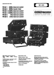
FM
2500 M
4000 M
5600 M
6000 T
8000 M
MANUALE USO E MANUTENZIONE
USAGE AND MAINTANCE MANUAL
MANUEL D'INSTRUCTIONS ET D'ENTRETIEN
cod 40928
MASE
FM
1
2
MASE
FM
2
3
MASE
FM
3
4
4
MASE
FM
FM2500
FM 8000
6
5
5
MASE
FM
FM 2500
FM 4000
6
MASE
FM
FM 5600
12
3
5
6
11
7
8
1
1
10
9
1
4
FM 6000
9
10
4
6
1
5
2
7
ECC
A.V.R.
3
7
1
8
3
MASE
FM
FM 8000
8
MASE
I
FM
INDICE
1)
NORME DI SICUREZZA
2)
CARATTERISTICHE TECNICHE DIMENSIONI E PESO
3)
COMPOSIZIONE DEL GRUPPO
4)
INSTALLAZIONE E CONTROLLI PRELIMINARI
4.1) Posizionamento del gruppo
4.2) Controlli preliminari
4.3) Combustibile
5)
UTILIZZO DEL GRUPPO
5.1) Avviamento
5.2) Impiego del gruppo
5.3) Protezioni e segnalazioni
5.4) Arresto del gruppo
6)
MANUTENZIONE
7)
SCHEMI ELETTRICI
PERICOLO
Indica che è necessario prestare attenzione al fine di non incorrere in serie conseguenze che
potrebbero provocare la morte del personale o possibili danni alla salute.
Situazione che potrebbe verificarsi durante il periodo di vita di un prodotto, sistema o impianto
considerato a rischio in materia di danni alle persone, alle proprietà, all’ambiente o di perdite economiche.
ATTENZIONE
CAUTELA
Indica che è necessario prestare attenzione al fine di non incorrere in serie conseguenze che
potrebbero portare al danneggiamento di beni materiali quali le risorse o il prodotto
INFORMAZIONI
Indicazioni di particolare importanza.
I disegni sono forniti a scopo esemplificativo. Anche se la macchina in vostro possesso si differenzia sensibilmente
dalle illustrazioni contenute in questo manuale la sicurezza e le informazioni sulla stessa sono garantite.
Il costruttore, nel perseguire una politica di costante sviluppo ed aggiornamento del prodotto, può apportare modifiche senza preavviso.
9
MASE
FM
I
2) CARATTERISTICHE TECNICHE
GRAZIE PER AVERE SCELTO UN PRODOTTO MASE.
Il presente libretto contiene le più importanti informazioni
per un corretto uso del generatore. Per la sicurezza e
soddisfazione del Cliente e per l’ affidabilità del gruppo
elettrogeno sono essenziali una corretta installazione e
verifica prima della consegna. Un controllo non accurato
o un errore di montaggio possono compromettere l’
efficienza del generatore e pregiudicare la sicurezza
dell’ utente. Tutte le informazioni e illustrazioni di questo
manuale si riferiscono al modello esistente al momento
della pubblicazione. Per eventuali ulteriori informazioni
La preghiamo di rivolgersi al più vicino centro di assistenza MASE che sarà lieto di assisterla.
La MASE si riserva il diritto di apportare modifiche senza
darne alcun preavviso. Nessuna parte o illustrazione di
questo manuale può essere riportata senza autorizzazione.
GENERATORE
2500 M
4000 M
5600 M
6000 T
8000 M
MOTORE
Brigss &
Stratton
Brigss &
Stratton
Brigss &
Stratton
Brigss &
Stratton
Brigss &
Stratton
TIPO
132232
195432
254422
254422
303400
1
1
1
1
2
c.c
206
319
400
400
480
POTENZA Hp (Na)
3.2
5.1
7.5
7.5
10.4
CONSUMO
1.6
1.7
3
3
4
3
12
12
12
9
3000
3000
3000
3000
3000
POT. CONT. (380 V)
-
-
-
5000
-
POT. CONT. (220 V)
1800
3000
4400
3000
6300
Nr. CILINDRI
CILINDRATA
Lt/h
CAPAC. SERB. Lt
GIRI /1'
MASE GENERATORS S.p.A.
1) NORME DI SICUREZZA
3) COMPOSIZIONE DEI GRUPPI
- Leggere attentamente tutte le informazioni contenute
in questo opuscolo: esse sono fondamentali per una
corretta installazione ed utilizzo del gruppo e per essere
in grado di intervenire tempestivamente in caso di necessità.
- Non consentire l’ uso del gruppo a persone non
competenti o che non siano state istruite adeguatamente.
- Non consentire a bambini od animali di avvicinarsi al
gruppo elettrogeno in funzione.
- Non accedere al generatore o al cruscotto di comando
a distanza con mani bagnate essendo il generatore una
potenziale fonte di shock se male utilizzato.
- I gas di scarico contengono monossido di carbonio ed
altri residui nocivi all’ organismo: è importante non fare
mai funzionare il gruppo in ambienti chiusi.
- Non far funzionare il gruppo in vicinanza di luoghi con
pericolo di esplosione o di incendio.
- Eventuali controlli sul gruppo elettrogeno vanno eseguiti a motore spento; controlli sul gruppo in funzione
vanno effettuati solo da personale specializzato.
- Il rifornimento di carburante va eseguito a motore
spento.
- Il collegamento a terra del gruppo va fatto con cavo di
rame di sezione non inferiore a 6 mmq.
I gruppi della serie FORMULA sono generatori sincroni
di c.a. monofase e/o trifase composti essenzialmente
da:
- Un telaio portante (Fig.1 Rif.1).
- Un alternatore sincrono autoeccitato ed autoregolato
(Fig. 1 Rif.2).
- Un motore (Fig.1 Rif.3) 4 tempi a benzina.
- Un cruscotto comandi (Fig.1 Rif.4) composto da:
1) Termico generale
2) Presa 2P+T
3) Interruttore generale
4) Spia funzionamento
5) Interruttore Stop
6) Morsetto C.C. 24V
7) Morsetto C.C. 12V
8) Morsetto C.C. (-)
9) Fusibile circuito C.C.
10) Contaore
11) Presa 3P+T
12) Termico 3 ~
13) Termico parziale 1~
ATTENZIONE
Nell’ utilizzo del generatore occorre tener presente
che nei luoghi bagnanti o molto umidi e nei luoghi
conduttori ristretti esiste l’ obbligo del rispetto degli
articoli 313 e 318 del D.P.R. 27/04/55 nr. 547, nonché
del Cap. 11, Sez. IV della norma C.E.I. 64-8.
10
MASE
FM
I
4) INSTALLAZIONE E CONTROLLI PRELIMINARI
5.3) Protezioni e segnalazioni
4.1) Posizionamento del gruppo
Il gruppo è dotato di alcune protezioni e segnalazioni che
lo salvaguardano da un anomalo funzionamento e scorretto utilizzo; essi sono :
- PROTEZIONE CIRCUITO c.a. il microdisgiuntore
termico automatico (Fig.2 Rif.1-13) interviene interrompendo l’ erogazione di potenza alle prese c.a. in caso di
sovraccarico o corto circuito. L’ intervento della protezione è visualizzato dal contemporaneo spegnimento della
lampada spia verde (Fig.2 Rif.4) o dal non funzionamento del contaore (Fig.2 Rif.10) sull’ FM 8000 e dall’
intervento del termico (Fig.2 Rif.1-12-13).
Per il riarmo è sufficiente, dopo aver individuato ed
eliminato la causa dell’intervento, attendere circa un
minuto e ripristinare il termico riportandolo nella posizione originaria.
- PROTEZIONE USCITA c.c. (solo FM8000) fusibile
10A (Fig.2 Rif.9).
- PROTEZIONE MANCANZA OLIO: questa protezione
spegne automaticamente il motore quando il livello dell’
olio scende sotto il livello minimo. L’ intervento di tale
sistema di protezione è segnalato da una lampada rossa
posta sul motore (Fig.5 Rif.1). Sul modello FM 8000 non
c’è alcuna lampada.
I gruppi vanno posizionati orizzontalmente, accertandosi che lo scarico non sia diretto contro nessun ostacolo
o sia posizionato ad almeno 2mt. da esso.
Effettuare inoltre il collegamento a terra con un cavo di
sezione non inferiore a 6 mmq. servendosi dell’ apposito
morsetto (Fig.3).
4.2) Controlli preliminari
Prima di ogni avviamento è bene controllare sempre:
- Il livello dell’ olio ed il livello del carburante nel serbatoio.
- Che il gruppo sia bene in equilibrio sui suoi punti di
appoggio.
- Che non vi siano utenze elettriche inserite.
- Che i necessari collegamenti siano eseguiti correttamente e non vi siano connessioni elettriche in cattivo
stato.
4.3) Combustibile
Il rifornimento si effettua tramite il tappo usando preferibilmente benzina normale NOR 84-86.
5.4) Arresto del gruppo
Prima di procedere allo spegnimento, scollegare gli
eventuali carichi applicati, chiudere il rubinetto del combustibile, fare girare a vuoto il gruppo per qualche decina
di secondi.
Per ottenere lo spegnimento del motore è necessario
agire sull’interruttore posto sul pannello strumenti
(Fig.2 Rif.5).
5) UTILIZZO DEL GRUPPO
5.1) Avviamento
Aprire il rubinetto del combustibile (Fig.4 Rif.1), tirare la
levetta dello starter (Fig.4 Rif.2) e posizionare l’ interruttore on-off (Fig.4 Rif.3) in posizione on; afferrare l’
impugnatura (Fig.4 Rif.4) e tirare dolcemente fino ad
avvertire la massima resistenza alla trazione (ciò indica
che il motore è in fase di compressione), tirare quindi con
uno strappo deciso; ad avviamento avvenuto riportare la
levetta dello starter nella posizione originaria. La presenza di tensione sull’ alternatore è segnalata dall’
accensione della lampada spia verde (Fig.2 Rif.4). Sull’
FM 8000 la presenza di tensione è segnalata dal funzionamento del contaore (Fig:2 Rif.10). Per avere tensione
alle prese è necessario posizionare il commutatore
(fig.2 Rif.3) in pos. 1.
N.B. Per i gruppi FM2500-8000 il comando Stop è posto
sul motore (Fig.6 Rif.1).
6)
MANUTENZIONE
PERICOLO
Qualsiasi intervento di manutenzione al gruppo va
effettuato a motore spento, dopo averlo lasciato
raffreddare a sufficienza e va eseguito solo da personale autorizzato.
5.2) Impiego del gruppo
Si raccomanda di seguire scrupolosamente le indicazioni riportate nel manuale fornito dal costruttore del motore, allegato ad ogni gruppo.
Se si prevede che il gruppo resti inattivo per lunghi
periodi si consiglia di:
- Sostituire l’ olio motore
- Smontare la candela e versare qualche goccia di olio
lubrificante pulito nel cilindro, far fare qualche giro al
motore per distribuire l’ olio, indi rimontare la candela.
- Pulire gli elementi del filtro aria.
- Svuotare il carburatore.
Prima di inserire qualsiasi utenza, fare girare a vuoto il
motore per qualche decina di secondi.
Ogni gruppo è dotato di due prese:
- entrambe monofase per i modelli 2500 - 4000 - 5600 8000 (Fig.2 Rif.2);
- una monofase ed una trifase per : il modello 6000 (Fig.2
Rif.2-11).
Le potenze disponibili alle prese sono quelle indicate
nelle caratteristiche tecniche e riportate sul cruscotto di
ogni gruppo.
11
MASE
FM
SCHEMI ELETTRICI
FM 2500
FM 8000
1
2
3
4
5
6
7
8
9
1
2
3
4
5
6
7
8
9
10
11
Diodo 25A 800V
Varistore
Rotore
Statore
Condensatore
Spia generatore
Interruttore prese AC
Interruttore termico
Presa 2p + t 16A
FM 4000
1
2
3
4
5
6
7
8
9
10
Diodo 25A 800V
Varistore
Rotore
Statore
Condensatore
Spia generatore
Interruttore prese AC
Interruttore termico
Presa 2p + t 16A
Interruttore ON-OFF
FM 5600
1
2
3
4
5
6
7
8
9
10
11
12
Diodo 25 A 800 V
Varistore
Rotore
Condensatore
Statore
Spia generatore
Interruttore prese
Interruttore termico
Interruttore termico
Presa 2p+t 16A
Presa 2p+t 32A
Interruttore ON-OFF
FM 6000
1
2
3
4
5
6
7
8
9
10
Rotore
Statore
Regolatore elettronico
Interruttore prese A.C.
Magnetotermico
Interruttore termico
Presa 2p+t 16A
Presa 3p+t 16A
Interruttore ON-OFF
Spia generatore
12
Rotore
Statore
Ponte diodi 25 A 400V
Contaore
Fusubile 10A
Interruttore termico
Presa 2p+t 16A
Condensatore
Pulsante stop
Diodo 20A 800V
Varistore
MASE
GB
FM
CONTENTS
1) SAFETY REGULATIONS
2) TECHNICAL PARTICULARS DIMENSIONS AND WETGHT
3) UNIT COMPONENT-PARTS
4) INSTALLATION AND PRELIMINARY CHECKS
4.1) Unit location
4.2) Preliminary checks
4.3) Fuel
5) GENERATOR USE
5.1 ) Starting
5.2) Unit use
5.3) Safety devices
5.4) Generator stop
6) MAINTENANCE
7) WIRING DIAGRAM
DANGER
A statement advising of the need to take care lest there be serious consequences resulting in
death of personnel or in hazard to health.
A situation that could occur during the lifetime of a product, system or plant that has the
potential for human injury, damage to property, damage to the environment, or economic loss.
WARNING
CAUTION A statement advising of the need to take care lest serious consequences result in harm to
material items such as the asset or the product.
INFORMATION Important information.
Drawing are provided by way of example. Should your machine be quite different from the illustrations contained in
this manual, the safety regulations and relevant information are always granted.
The manufacturer's policy of constant development and updating may lead to modifications without prior notice.
13
MASE
FM
GB
2 TECHNICAL FEATURES
CONGRATULATIONS ON HAVING CHOSEN A MASE
PRODUCT
This manual contains all the necessary information for
proper installation and use of the generator. It’s essential,
either for the customer’s safety and satisfaction or for
good reliability of the generator, to carry out proper
installation and a careful pre-delivery test.
A wrong installation or an oversight on testing may
compromise the efficiency of the generator and even
jeopardize the customer’s safety.
All information and illustrations in this handbook refer to
the latest produced model at the time of printing.
For any further information, please get in touch with the
nearest MASE SERVICE CENTER, they’ll be pleased to
help you at any time.
MASE reserve the right to introduce changes without
prior notice. No part or illustration contained in this
handbook can be reproduced without previous approval
by MASE
GENERATOR
2500M 4000M 5600M
ENGINE
Brigss& Brigss& Brigss& Brigss& Brigss&
Stratton Stratton Stratton Stratton Stratton
TYPE
132232 195432 254422 254422 303400
Nr.CYLINDER
6000T
8000M
1
1
1
1
2
DISPLACEMENT c.c
206
319
400
400
480
POWER Hp(Na)
3.2
5.1
7.5
7.5
10.4
CONSUPTION Lt/h
1.6
1.7
3
3
4
TANKCAPACITY Lt
3
12
12
12
9
3000
3000
3000
3000
3000
CONT.POW.(380V)
-
-
-
5000
-
CONT.POW.(220V)
1800
3000
4400
3000
6300
RPM/1'
MASE GENERATORS S.p.A.
1) SAFETY REGULATIONS
3) UNITCOMPONENT-PARTS
- Read carefully all the instructions given in this handbook:
they are of the utmost importance for correct istallation
and use of the unit and for prompt intervention in case of
need.
- Do not allow unskilled or untrained peopie to use the
unit.
- Do not allow children or animals to get close to the
generator while it’s working.
- Do not handle the generator or the remote control panel
with wet hands; any misuse may cause electric shocks.
- Exhaust gas contains carbon monoxide and other
residues which are injurious to health therefore it’s
necessary not to make the generator work in closed
areas.
- Do not make the generator work near those areas
where dangers of explosion or fire do exist.
- Any testing of the unit is to be carried out only when the
engine is stopped. Possible checks on the generator
when it’s running have to be performed only by skilled
workers.
- Refuelling must be carried out only when the engine is
stopped.
- Earth-connection has to be made through copper
cables having 6 sq.mms. cross-section at least.
The gensets of the FORMULA series are singie-phase
and/or three-phase A.C. synchronous generators
essentially composed of:
- a supporting frame (Fig. 1 Ref. 1). A self-excited and
self-regulating synchronous alternator (Fig. 1 Ref. 2).
- A four-stroke gasoline engine (Fig. 1 Ref. 3).
- An instrument panel (Fig. 1 Rif. 1) with:
1
2
3
4
5
6
7
8
9
10
11
12
13
14
General thermal switch
Single phase socket
General switch
Generator warning ligh
Stop switch
C.C. 24V terminal
C.C. 12V terminal
C.C. terminal (-)
C.C. circuit fuse
Hours meter
Three phase socket
3 ~ thermal switch
1 ~ thermal switch
MASE
FM
GB
sockets are indicated in the specifications as well as on
the instrument panel of each unit.
4) INSTALLATION ANDPRELIMINARY CHECKS
4.1) Positioning the unit
5.3) Safety devices
Position the power unit horizontally and make sure that
the gas exhaust is not turned towards any obstacle or
that this is at least 2 m. away from the unit. Make the
earth connection by means of the appropriate terminal
and a wire having a section of not less than 6 sq.mm
(Fig. 3).
— Make sure that the fuel and the oil filler caps are well
secured.
The unit is equipped with a number of safety and warning
devices which protect it from abnormal operation and
improper use; These include:
— A. C. ClRCUIT SAFETY DEVICE:
the thermal circuit breaker (Fig. 2 Ref. 1-13) intervenes
in case of overloading or shortcircuiting. The coming into
operation of the circuit breaker is signalled by the turning
off of the green pilot-light (Fig. 2 Ret. 4) as well as by not
running of the hoursmeter (Fig. 2 Ref. 10) on FM 8000
and by the intervention of the thermic (Fig. 2 Ref. 1-1213). To reset the circuit breaker after having found and
eliminated the source of trouble wait for about a minute,
and bring the
thermic back tooriginal position.
— Make sure that the unit is at an equilibrium on its points
of support.
— D.C. OUTPUT PROTECTION
DEVICE (only FM 800). Fuse 10 A (Fig. 2 Ref. 9).
— Make sure that there are no electrical appliances
connected.
— OIL WARNING DEVICE: This
device stops the unit while in operation or prevents it from
starting, if the oil level is below minimum. The oil warning
device will cause the red lamp (Fig. 5 Ref. 1) to flash. On
FM 8000 model there is no lamp.
4.2) Preliminary checks
Before start up and particulariy after every maintenance
operations it is a good rule to:
— Check the fuel and oil levels.
4.3) Fuel
Unscrew the fuel filler cap and fill the
tank prefarably with regular petrol NOR
84-86.
5.4) Turning off the unit
Before turning off, disconnect any connected appliances,
turn off the fuel tap7 let the motor run idle for a few tens
of seconds, turn the switch (Fig. 2 Ref. 5) and release
when the unit has actually stopped.
5) USE OF THE UNIT
N.B. For FM 2500-8000 the stop device is on the engine
(Fig. 6 Ref. 1).
5.1) start up
Open the fuel tap (Fig. 4 Ref. 1), and pull the starting
device lever (Fig. 4 Ref. 2); position the switch on-off
(Fig.4 Ref. 3) in position “on”; grab the handle (Fig. 4 Ref.
4) and pull softly until you feel the highest tensile strength
(this indicates that the motor is In compression). Then,
give it a decisive tug. Once the power unit is started up,
bring the starting device lever to the original position.
The availability of tension at the sockets is signalled by
the lighting of the green pilot-lamp (Fig. 2 Ref. 4) on the
FM 8000 the presence of tension is signalled by the
running of the hoursmeter (Fig. 2 Ref. 10).
In order to have voltage at the sockets, it is necessary to
position the commutator (Fig. 2 Ref. 3) in Pos. Nr. 1.
6) MAINTENANCE
DANGER
All maintenance work shall be carried out power-off
by authorized personnel only after having let it cool
down sufficiently. We recommend strictly keeping
to the instructionss contained in the motor
manufacturer7s manual supplied along with each
unit.
If you expect the unit to remain unused for long periods,
we recommend the following:
— Replace engine oil.
— Take out the spark-plugs pour a few drops of lubricant
oil into the cylinder, let the engine complete some
revolutions so as to spread about the oil, then put the
spark-plug back in place.
—Clean the air filter elements.
—Empty the carburettor.
5.2) Use of the unit
Before connecting any appliances, let the motor run idie
for a few tens of seconds. Each unit is equipped with
two sockets: —both of the single-phase for the models
2500-4000-5600-8000 (Fig. 2 Ref. 2).
— One single-phase and one three-phase for the model
6000 (Fig. 2 Ref. 2-11). The voltages available at the
15
MASE
FM
WIRING DIAGRAM
FM 2500 M
FM 8000 M
1
2
3
4
5
6
7
8
9
1
2
3
4
5
6
7
8
9
10
11
Diode 25 A 800 V
Varistor
Rotor
Capacitor
Stator
Generator warning light
A.C. socket switch
Thermal Switch
Socket 16A
FM 4000 M
1
2
3
4
5
6
7
8
9
10
Diode 25 A 800 V
Varistor
Rotor
Capacitor
Stator
Generator warning light
A.C. socket switch
Thermal Switch
Socket 16A
ON-OFF switch
FM 5600 M
1
2
3
4
5
6
7
8
9
10
11
12
Diode 25 A 800 V
Varistor
Rotor
Capacitor
Stator
Generator warning light
A.C. socket switch
Thermal Switch
Thermal Switch
Socket 16A
Socket 32A
ON-OFF switch
FM 6000 T
1
2
3
4
5
6
7
8
9
10
Rotor
Stator
Electronic regulator
A.C. socket switch
Magnetothermal switch
Thermal Switch
Socket 16A
Socket 16A
ON-OFF switch
Generator warning light
16
Rotor
Stator
Diode 25 A 400 V
Hours Meter
Fuse 10A
Thermal Switch
Socket 16A
Capacitor
Stop buton
Diode 20A 800V
Varistor
MASE
F
FM
INDEX
1)
NORMES DE SECURITE
2)
CARACTERISTIQUES TECHNIQUES DIMENSIONS ET POIDS
3)
COMPOSANTS DU GROUPE
4)
INSTALLATION ET CONTROLES PRELJMINAIRES
4.1) Mise en place du groupe
4.2) Controles preliminaires
4.3) Combustible
5)
EMPLOI DU GROUPE
5.1 ) Demarrage
5.2) Emploi du generateur
5.3) Dispositifs de protection
5.4) Arret du groupe
6)
ENTRETIEN
7)
SCHEMAS ELECTRIQUES
DANGER
Indique qu'il faut bien faire attention à ne pas courir des risques entraìnant de graves
conséquences qui pourraient causer la mort du personell ou endommager la santé.
ATTENTION
Situation qui pourrait se vérifier pendant la vie utile d'un produit, système ou bien installation
considérés à risque pour les personnes, la propriété, l'environnement ou bien cause de pertes économiques.
PRECAUTION
Indique qu'il est nécessaire de faire la plus grande attention afin de ne pas courir des risques
pouvant entraìner de graves conséquences, ainsi que l'endommagement des biens matériels, tels que les
ressources ou le produit.
INFORMATIONS Indications d'importance particulière .
Les plans ne sont donnés qu'à titre d'example.Meme si votre machine présentait des caractéristiques différente des
illustrations contenues dans le présent livret, la sùreté ainsi que les avertissement sur celle-ciseraient garantis.
Le constructer, suivant une politique de développement et de mise à jour de ses produits continuelles, peut apporter
des modifications dans ce manuel sans préavis.
17
MASE
FM
F
NOUS VOUS FELICITONS D’AVOIR FAIT
L’ACQUISITION D’UN PRODUIT MASE.
2 CARACTERISTIQUES TECHNIQUES
Ce manuel vous apportera une connaissance de base
des caractéristiques de l’installation et du fonctionnement
pour le meilleur emploi du générateur. Pour garantir la
sécurité la satisfaction du client et la fiabilité du groupe
électrogéne, il est essentiel que l’installation et l’entretien
avant la livraison soient correctement effectués.
Une erreur ou une négligence pendant le montage ou
l’entretien pourraient déterminer un mauvais
fonctionnement du groupe et porter préjudice au client.
Toutes les informations et les illustrations présentées
dans ce manuei se rapportent au modéle existant
aumoment de la publication.
Si vous avez d’autres questions concernant le
fonctionnement ou l’entretien du produit, veuillez consulter
le Centre d’Assistance MASE le plus proche.
MASE se réserve le droit d’apporter de modifications
sans avis préalable.
Aucune partie ou illustration de ce manuel ne peut ètre
reproduite sans autorisation.
Mase Generators S.p.A.
GENERATEUR
2500 M 4000 M 5600 M
6000T
8000 M
MOTEUR
Brigss & Brigss & Brigss & Brigss & Brigss &
Stratton Stratton Stratton Stratton Stratton
TYP
132232 195432 254422 254422 303400
1
1
1
1
2
CYLINDREE c.c
206
319
400
400
480
PUISSAN Hp (Na)
3.2
5.1
7.5
7.5
10.4
CONSOMM.
Lt/h
1.6
1.7
3
3
4
3
12
12
12
9
3000
3000
3000
3000
3000
-
-
-
5000
-
Nr.CYLINDRE
CAPACITÈ
RESERVOR
TOURS/1'
PUIS. CONT. (380
V)
Lt
1) NORMES DE SECURITE
3) COMPOSANTS DES GROUPES
— Lire attentivement toutes les instructions contenues
dans ce manuel: elles sont fondamentales pour une
installation correcte et un bon emploi du groupe et
permettent en cas de besoin, d’intervenir en temps utile.
— Ne pas permettre l’emploi du groupe a des personnes
incompétentes.
— Ne pas permettre aux enfants et aux animaux l’approche au groupe électrogène en marche.
— Etant donne que si le générateur est mal utilise, il
représente une potentielle source de secousses électriques, ne pas utiliser le générateur si l’on a les mains
mouillées.
— Les gaz d’échappement contiennent du monoxyde
de carbone et d’autres résidus nocifs a l’organisme: il est
donc important de ne jamais faire fonctionner le groupe
dans des milieux fermes.
— Ne pas faire fonctionner le groupe a proximité de lieux
comportant des risques d’explosion ou d’incendie.
— Pour d’éventuels contrôles au groupe électrogène, il
est nécessaire d’arrêter le moteur; des contrôles au
groupe en marche devront être effectues uniquement
par du personnel spécialisé.
— Faire le plein de carburant uniquement lorsque le
moteur est a l’arrêt.
— Le raccordement a terre du groupe doit être fait avec
un câble en cuivre de 6 mm2 au moins de diamètre.
Les groupes de la série FORMULA sont des générateurs synchrones a courant alternatif monophasés ou
triphasés. Ils comprennent:
— un châssis portant (Fig. Ref. 1).
— un alternateur synchrone pourvu d’autoexcitation et
d ‘ autorégulation (Fig . 1 Ref. 2).
— Un moteur (Fig. 1 Ref. 3) 4 temps a essence.
— Un tableau des commande (Fig. 1 Ref. 4) avec:
1
2
3
4
5
6
7
8
9
10
11
12
13
18
Thermique général
Prise monophasée
Interrupteur général
Lampe témoin générateur
Interrupteur stop
Borne DC 24V
Borne DC 12V
Borne DC Fusible circuit DC
Compte-heures
Prise triphasée
Thermique 3 ~
Thermique 1 ~
MASE
FM
F
4) INSTALLATION ET CONTROLES PRELIMINAIRES
5.3) Dispositifs de protection et d’avertissement
4.1) Mise en place du groupe
Le générateur est équipe d’un ensemble des dispositifs
de protection et d’avertissement qui le garantissent
contre un emploi incorrect et contre des inconvénients
dans son fonctionnement; ce sont:
— PROTECTION DU CIRCUIT c.a.: le disjoncteur thermique (Fig. 2 Ref. 1-13) interrompt le débit de courant a
la prise dans le cas de surcharge ou de court-circuit.
L’intervention de la protection est signalée par l’extinction de la lampetémoin verte (Fig. 2 Ref. 4) ou bien par
non fonctionnement du compte-heures (Fig. 2 Ref. 10)
sur le FM 8000 et par l’intervention du Thermique (Fig.
2 Ref. 1-12-13). Après avoir trouve et élimine la cause
du trouble, attendez une minute environ, réactiver le
thermique et ramenez-le sur sa positon initiale.
— PROTECTION SORTIE D.C. (seulement FM 8000).
Fusible 10 A (Fig. 2 Ref. 9)
— PROTECTION O.W.D. (oil warning device) sur le
niveau de l’huile: il arrête le groupe pendant la marche
ou bien il en empêche le démarrage au cas ou le niveau
de l’huile serait au dessous du minimum. L’intervention
de la protection est signalée par le clignotement de la
lampe témoin rouge (Fig. 5 Ref. 1). Sur le modèle FM
8000 il n’y a pas de lampes témoins
Le générateur doit être installe en position horizontale en
vérifiant que l’échappement des gaz ne soit pas dirige
contre des obstacles, ou qu’il soit place au moins a la
distance de deux mètres. En outre effectuer le branchement a terre du groupe en utilisant la borne prévue a cet
effet et un câble pas inférieur a 6 mm.2 de section
(Fig. 3).
4.2) Conseils généreux
Avant tout démarrage et surtout après avoir effectue
n’importe quelle intervention d’entretien, il est de règle
de vérifier toujours:
— Le niveau de l’huile et du carburant.
— Si le bouchon de remplissage de l’huile et celui du
carburant sont bien fermes.
— Si le groupe est bien en équilibre sur ses points
d’appui.
— Si les charges électrocutes sont bien débranchées .
4.3) Combustible
Devisiez le bouchon et remplissez le réservoir avec
essence ordinaire NOR 84-86 de préférence.
5) EMPLOI DU GROUPE
5.4) Arrêt du groupe
Avant d’étendre le groupe débrancher les charges éventuellement appliquées, fermer le robinet du combustible,
faire tourner a vide le groupe pendant quelque dizaine
de secondes, ensuite tourner l’interrupteur (Fig. 2 Ref. 5)
jusqu’a la complète extinction .N.B. Pour les groupes FM
2500-8000 le stop est posictionné sur le moteur (Fig. 1)
5.1) Démarrage
Ouvrir le robinet du combustible (Fig. 4 Ref. 1) et tirer le
évier du starter (Fig. 4 Ref. 2); positionner l’interrupteur
on-off (Fig. 4 Ref. 3) sur la position «on»; prendre la
poignée (Fig. 4 Ref. 4) et tirer doucement jusqu’a ce que
l’on constate le maximum de la résistance a la traction
(cela indique que le moteur se trouve a la phase de
compression); tirer ensuite d’un coup sec; après les
démarrage le levier du starter dans la position originaire.
L’allumage de la lampe témoin verte signale la présence
de tension aux prises (Fig. 2 Ref. 4). Sur le FM 8000
la présence de tension est signalée par le fonctionnement du compte heures.
Pour avoir tension aux prises, il est necessaire de
positionner le commutateur (Fig. 2 Ref. 3) sur la Pos. 1.
6) ENTRETIEN
DANGER
Toute intervention d’entretien au groupe électrogène doit être effectuée a moteur éteint, après, qu’il
a suffisamment refroidi et ne doit être faite que par
du personnel autorise.
Il est recommande de suivre scrupuleusement les instructions du manuel fourni par le constructeur du moteur,
annexe a chaque groupe.
Si l’on prévoit que le groupe ne soit pas utilisé pendant
une longue période, il est conseille d’effectuer les opérations suivantes:
— Changer l’huile du moteur.
— Démonter la bougie et verser quelques gouttes
d’huile lubrifiante propre sur le cylindre, faire quelques
tours au moteur pour bien distribuer l’huile, enserre
remonter la bougie.
— Nettoyer les éléments du filtre de l’air.
— Vidanger le carburateur.
5.2) Emploi du groupe
Avant de brancher n’importe quelle charge faire fonctionner a vide le moteur pendant quelque dizaine de
secondes. Chaque groupe est dote de deux prises:
— L’une et l’autre monophasée pour les modèles 25004000-5600-8000 (Fig. 2 Ref. 2).
— Une prise monophasé et une prise triphasée pour le
modèle 6000 (Fig. 2 Ref. 2-11).
Les puissance disponibles aux prises sont celles indiquées dans les caractéristiques techniques et indiquées
sur le tableau de chaque groupe.
19
MASE
FM
FM 2500 M
FM 8000 M
1
2
3
4
5
6
7
8
9
1
2
3
4
5
6
7
8
9
10
11
Diodes 25 A 800V
Varience
Rotor
Condensateur
Stator
Lampe-temoin generateur
Interrupteur prises A.C.
Interrupteur thermique
Prise 16A
FM 4000 M
1
2
3
4
5
6
7
8
9
10
Diodes 25 A 800V
Varience
Rotor
Condensateur
Stator
Lampe-temoin generateur
Interrupteur prises A.C.
Interrupteur thermique
Prise 16A
Interrupteur ON-OFF
FM 5600 M
1
2
3
4
5
6
7
8
9
10
11
12
Diodes 25 A 800V
Varistor
Rotor
Condensateur
Stator
Lampe-temoin generateur
Interrupteur prises A.C.
Interrupteur thermique
Interrupteur thermique
Prise 16A
Prise 32A
Interrupteur ON-OFF
FM 6000 T
1
2
3
4
5
6
7
8
9
10
Rotor
Stator
Régulateur électronique
IInterrupteur prises A.C.
Interrupteur magnetotermique
Interrupteur thermique
Prise 16A
Prise 16A
Interrupteur ON-OFF
Lampe-temoin generateur
20
Rotor
Stator
Point diodes 25 A 400V
Compte-heures
Fusible 10A
Interrupteur thermique
Prise 16A
Condensateur
Poissoir arret
Diodes 20 A 800V
Varistor