1
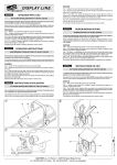
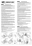
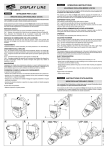
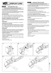
®
ITALIANO
DISPLAY LINE
ISTRUZIONI PER L’USO
3
OROLOGIO DIGITALE A CRISTALLI LIQUIDI (C52163)
MO
DE
ON
OF
F
HO
UR
Il presente foglio di istruzioni deve essere letto unitamente al manuale di istruzioni fornito
con il proiettore sul quale si intende montare questo accessorio.
SE
LE
CT
12
24
AD
JU
ST
E
Questo accessorio può essere montato esclusivamente sul proiettore V.I.P. 150 PFC -nel quale
deve essere obbligatoriamente montato il filtro anticalore (C52183)-, in abbinamento con il supporto
portaobiettivo (fornito di serie con il proiettore) e con un obiettivo. Può essere montato singolarmente o in combinazione con altri accessori.
PREDISPOSIZIONE PROIETTORE
B
Fig. 1 - Servendosi di un cacciavite a punta piana svitare le due viti (A) presenti sulla flangia
anteriore del proiettore V.I.P. 150 PFC.
Fig. 2 - Posizionare sulla flangia anteriore il filtro anticalore (B) in modo da far coincidere i fori
svasati (C) con i fori dai quali sono state tolte le viti (A). Inserire nei due fori (C) le viti a testa
svasata (D) e stringerle con un cacciavite a punta piana.
F
4
ON
MO
DE
OF
F
HO
UR
SE
LE
CT
12
AD
JU
ST
24
MONTAGGIO OROLOGIO
Fig. 3 - Posizionare l’accessorio in corrispondenza della flangia anteriore dell’apparecchio in modo
tale che il filetto dei volantini (E) entri nei fori (F) presenti sul supporto del filtro anticalore (B), quindi
serrare adeguatamente i volantini (E). I volantini (E) possono essere rimossi, semplicemente
tirandoli verso l’esterno, e reinseriti dal lato opposto dell’accessorio, questo al fine di orientare
correttamente la proiezione dell’ora, in alcune installazioni particolari, descritte più avanti.
Fig. 4 - La posizione in cui montare l’accessorio è normalmente quella con la ventola (G) posta
verso la parte inferiore del proiettore e rivolta verso l’obiettivo.
Quando si vuole utilizzare uno specchio, l’orologio deve essere montato con la ventola (G) posta
verso la parte inferiore del proiettore ma rivolta verso il corpo del proiettore. Per fare questo è
necessario invertire il lato di inserimento dei volantini (E), come precedentemente spiegato.
Fig. 5 - Se la proiezione avviene su pavimento, in entrambi i casi sopra descritti, l’orologio può
essere montato anche con la ventola (G) posta verso la parte superiore del proiettore, a seconda
del lato in cui si intende leggere l’ora.
G
E
MONTAGGIO IN COMBINAZIONE CON ALTRI ACCESSORI
Fare riferimento alle istruzioni per l’uso degli altri accessori. Come norma generale prestare attenzione,
nel montaggio, a non fare entrare in contatto fra loro le parti in movimento dei diversi accessori.
FUNZIONAMENTO
G
L’orologio a LCD è continuamente alimentato grazie alla presenza al suo interno di una pila che
ne garantisce il funzionamento per un periodo superiore a 2 anni. Quando si accende il proiettore
verificare che la ventola (G) cominci a girare automaticamente, se ciò non dovesse succedere, si
consiglia di non utilizzare l’accessorio poiché il display si danneggerebbe in breve tempo.
REGOLAZIONI
Fig. 6 - Posizionare il selettore “HOUR” nella posizione 12 se si desidera il conteggio delle ore da
1 a 12 AM/PM, oppure nella posizione 24 se si preferisce il conteggio da 0 a 23.
Per effettuare la regolazione delle ore e dei minuti porre il selettore “MODE” in posizione ON,
quindi, con un oggetto appuntito, premere il pulsante “SELECT” e verificare che le cifre delle ore
comincino a lampeggiare. In questa condizione, premendo il pulsante “ADJUST” le ore vengono
incrementate di una unità per ogni pressione. Premendo nuovamente il pulsante “SELECT” le cifre
dei minuti cominciano a lampeggiare, di conseguenza, premendo il pulsante “ADJUST” è possibile
incrementare i minuti. Premere nuovamente il tasto “SELECT” per concludere la procedura di
regolazione, quindi spostare il selettore “MODE” in posizione OFF.
5
G
SOSTITUZIONE BATTERIA
G
24
12
AD
SE
MO
JU
LE
ST
Fig. 7 - Servendosi della chiave a brugola 2 mm (cod. 050002) in dotazione con l’accessorio, estrarre
le 6 viti (H) e rimuovere la piastra di copertura (I). Individuare la batteria (J) e toglierla dal supporto
(K), quindi inserire una batteria nuova rispettando la polarità indicata sul supporto stesso.
IMPORTANTE: Utilizzare una batteria alcalina tipo AAA con tensione ai contatti di 1,5V.
Riposizionare la piastra di copertura (I) e fissarla inserendo le 6 viti (H).
CT
DE
ON
MANUTENZIONE
Ad eccezione della sostituzione della batteria, l’accessorio non richiede alcuna manutenzione
ordinaria, e in caso di malfunzionamento deve essere affidato a un tecnico autorizzato. La pulizia
periodica dello schermo LCD e del filtro anticalore va effettuata con un panno antistatico oppure
con un panno morbido e un detersivo per vetro non corrosivo.
CORREZIONE DI SEMPLICI ANOMALIE DI FUNZIONAMENTO
Il display è spento:
• Sostituire la batteria.
La ventola non funziona con proiettore acceso:
• Verificare che i due contatti laterali presenti sull’accessorio siano a contatto con le barrette
elettrificate del proiettore.
Si notano aloni sulla proiezione:
• Effettuare l’operazione di pulizia periodica.
1
7
6
2
B
C
®
Cod. C52163
D
ON
OFF
SELECT
MODE
ADJUST
HOUR
12
A
24
K
J
I
H
ENGLISH
OPERATING INSTRUCTIONS
FRANÇAIS
INSTRUCTIONS D’UTILISATION
LIQUID CRYSTAL DISPLAY DIGITAL CLOCK (C52163)
HORLOGE NUMERIQUE A CRISTAUX LIQUIDES (C52163)
This instructions sheet needs to be read together with the instructions manual supplied
with the projector on which you plan to fit this accessory.
Lire la présente fiche d'instructions en même temps que le manuel d'instructions fourni
avec le projecteur sur lequel l'accessoire doit être monté.
This accessory may only be fitted on the V.I.P. 150 PFC projector -in which must be used the
heat resistant filter (C52183)- with the lens holder mounting (supplied as standard with the
projector) and a lens. It can be mounted on its own or with other accessories.
Cet accessoire peut être monté exclusivement sur le projecteur V.I.P. 150 PFC -dans lequel on
doit obligatoirement monter le filtre antichaleur (C52183)- en association avec le support
d'objectif (fourni de série avec le projecteur) et avec un objectif. Il peut être monté seul ou en
combinaison avec d'autres accessoires.
PREPARING THE PROJECTOR
Fig. 1 - Using the screwdriver with a flat tip, unscrew the two screws (A) located on the front
flange of the projector V.I.P. 150 PFC.
Fig. 2 - Position the heat resistant filter (B) on the front flange in order to match the flared holes
(C) with the holes from which the screws (A) have been removed. Insert the countersunk screws
(D) in the two holes (C), and tighten them using a screwdriver with a flat tip.
AGENCEMENT DU PROJECTEUR
Fig. 1 - A l’aide d’un tournevis pour vis à fente, dévisser les deux vis (A) situées sur la bride
antérieure du projecteur V.I.P. 150 PFC.
Fig. 2 - Positionner le filtre antichaleur (B) sur la bride antérieure, de façon à faire coïncider les
trous fraisés (C) avec les trous dont on a enlevé les vis (A). Introduire les vis à tête fraisée (D)
dans les deux trous (C) et les serrer avec un tournevis pour vis à fente.
MOUNTING THE CLOCK
MONTAGE HORLOGE
Fig. 3 - Position the accessory, making it correspond with the front flange of the fitting, so that
the thread of the handwheels (E) enters the holes (F) located on the mounting of the heat
resistant filter (B). Then tighten the handwheels (E) appropriately. The handwheels (E) can be
removed by simply pulling them outwards, and then reinserted on the opposite side of the
accessory. This allows you to direct the projection of the time correctly in certain installations,
described later.
Fig. 4 - The accessory is normally mounted with the fan (G) positioned towards the lower part
of the projector and turned towards the lens.
When you want to use a mirror, the clock must be mounted with the fan (G) positioned towards
the lower part of the projector but facing the projector body. In order to do this, you need to invert
the inserting side of the handwheels (E), as explained above.
Fig. 5 - If the projection takes place on the floor, for both cases described above, the clock can
also be mounted with the fan (G) positioned towards the upper part of the projector, on the side
where you want to see the time.
Fig. 3 - Positionner l’accessoire au niveau de la bride antérieure de l’appareil de façon à ce que
le filet des volants (E) entre dans les trous (F) situés sur le support du filtre antichaleur (B), puis
serrer adéquatement les volants (E). Sur certaines installations particulières, décrites par la
suite, on peut tout simplement enlever les volants (E) en les tirant vers l’extérieur et les
réintroduire du côté opposé de l’accessoire afin d’orienter correctement la projection de l’heure.
Fig. 4 - La position sur laquelle monter l’accessoire est normalement celle avec le ventilateur (G)
placé vers la partie inférieure du projecteur et orienté vers l’objectif.
Si on désire utiliser un miroir, l’horloge doit être montée avec le ventilateur (G) placé vers la
partie inférieure du projecteur mais orienté vers le corps du projecteur. Pour ce faire, il faut
inverser le côté d’introduction des volants (E), comme cela a précédemment été expliqué.
Fig. 5 - Si la projection est effectuée sur le sol, dans les deux cas décrits ci-dessus, l’horloge
peut être montée également avec le ventilateur (G) placé vers la partie supérieure du projecteur,
en fonction du côté dans lequel on désire lire l’heure.
MOUNTING IN COMBINATION WITH OTHER ACCESSORIES
MONTAGE EN COMBINAISON AVEC D’AUTRES ACCESSOIRES
Refer to the instructions when operating the other accessories. As general rule, pay attention
when mounting, so as not to let the moving parts of the different accessories come into contact
with each other.
Se reporter aux instructions pour l'utilisation des autres accessoires. En règle générale, veiller
pendant le montage à ce que les parties en mouvement des différents accessoires n'entrent pas
en contact entre elles.
OPERATION
FONCTIONNEMENT
The LCD clock has a constant power supply thanks to a battery inside it which guarantees
operation for over 2 years. When the projector is switched on, check that the fan (G) starts to
turn automatically. If this does not happen, we advise against using the accessory as the display
will soon get damaged.
L’horloge à cristaux liquides est toujours alimentée grâce à la présence dedans d’une pile qui
assure son fonctionnement pendant une période supérieure à 2 ans. Quand on allume le
projecteur, contrôler que le ventilateur (G) commence à tourner automatiquement ; en cas
contraire, il est conseillé de ne pas utiliser l’accessoire car l’afficheur s’endommagerait très
rapidement.
REGULATIONS
Fig. 6 - Position the selector “HOUR” on 12 if you want the hour counting from 1 to 12 AM/PM,
or position it on 24 if you prefer counting from 0 to 23.
To adjust the hours and minutes, set the selector “MODE” to “ON”. Then using a pointed object,
press the push-button “SELECT” and check that the figures relating to the hours starts to flash.
By pressing the push-button “ADJUST”, the hours will increase by one unit each time you press.
Press “SELECT” again, and the figures relating to the minutes start to flash, so press “ADJUST”
to increase the minutes. Press “SELECT” to conclude the adjustment procedure, then turn the
selector “MODE” to “OFF”.
REPLACING THE BATTERY
Fig. 7 - Using the 2 mm Allen wrench (code 050002) supplied with the accessory, extract the
6 screws (H) and remove the covering plate (I). Find the battery (J) and take it out of its mounting
(K). Then insert a new battery while observing the polarity indicated on the mounting.
REGLAGES
Fig. 6 - Positionner le sélecteur “HOUR” sur la position 12 si on désire le comptage des heures
de 1 à 12 AM/PM ou dans la position 24 si on préfère le comptage de 0 à 23.
Pour effectuer le réglage des heures et des minutes, placer le sélecteur “MODE” sur la position
ON, puis, avec un objet pointu, appuyer sur le bouton “SELECT” et vérifier que les chiffres des
heures commencent à clignoter. Dans cette condition, en appuyant sur le bouton “ADJUST”, les
heures augmentent d’une unité à chaque pression. En appuyant de nouveau sur le bouton
“SELECT”, les chiffres des minutes commencent à clignoter, ensuite, en appuyant sur le bouton
“ADJUST”, on peut augmenter les minutes. Appuyer de nouveau sur le bouton “SELECT” pour
terminer la procédure de réglage. Enfin, déplacer le sélecteur “MODE” sur la position OFF.
REMPLACEMENT DE LA PILE
IMPORTANT: Use an alkaline battery type AAA with a voltage to contacts of 1.5V.
Reposition the covering plate (I) and fasten it by inserting the 6 screws (H).
Fig. 7 - A l’aide de la clé à six pans mâle de 2 mm (code 050002) fournie avec l’accessoire,
extraire les 6 vis (H) et enlever la plaque de protection (I). Repérer la pile (J) et l’enlever du
support (K), puis introduire une pile neuve en respectant la polarité indiquée sur le support.
MAINTENANCE
IMPORTANT: Utiliser une pile alcaline type AAA avec tension aux contacts de 1,5V.
Positionner de nouveau la plaque de protection (I) et la fixer en introduisant les 6 vis (H).
Apart from battery replacement, the accessory needs no routine maintenance, and in the case
of malfunctioning, the work must be assigned to an authorized technician. The LCD screen
and heat resistant filter must be periodically cleaned with an antistatic cloth or a soft cloth and
a non-corrosive detergent for glass.
CORRECTING STRAIGHTFORWARD OPERATING TROUBLE
The display is off:
• Replace the battery.
The fan does not work with the projector switched on:
• Check that the two lateral contacts on the accessory are in contact with the projector’s
electrified bars.
Rings are seen on the projection:
• Carry the periodical cleaning operation.
ENTRETIEN
A l’exception du remplacement de la pile, l'accessoire ne nécessite aucun entretien ordinaire, et
en cas de mauvais fonctionnement, il doit être confié à un technicien agréé. Pour le nettoyage
périodique de l’afficheur LCD et du filtre antichaleur, utiliser un chiffon antistatique ou un chiffon
doux imbibé de détergent pour vitres, non corrosif.
CORRECTION DE SIMPLES ANOMALIES DE FONCTIONNEMENT
L’afficheur est éteint:
• Remplacer la pile.
Le ventilateur ne fonctionne pas avec le projecteur allumé:
• S'assurer qu'il y a un contact entre les deux contacts latéraux présents sur l’accessoire et les
guides électrifiés du projecteur.
En cas de halos sur la projection:
• Effectuer l'opération de nettoyage périodique.
DEUTSCH
BEDIENUNGSANLEITUNG
ESPAÑOL
INSTRUCCIONES DE USO
FLÜSSIGKRISTALL-DIGITALUHR (LCD) (C52163)
RELOJ DIGITAL DE CRISTALES LIQUIDOS (C52163)
Diese Bedienungsanleitung sollte parallel mit dem Bedienungshandbuch des Projektors,
mit dem dieses Zubehörteil benutzt wird, gelesen werden.
La presente hoja de instrucciones debe leerse junto con el manual de instrucciones del
proyector en el cual se montará este accesorio.
Dieses Zubehörteil kann ausschliesslich am Projektor V.I.P. 150 PFC, in Kombination mit dem
Hitzefilter (C52183), der unbedingt im Projektor eingesetzt werden muß, und dem (serienmäßig
mit dem Projektor mitgelieferten) Objektivhalter und mit einem Objektiv montiert werden.
Es kann einzeln oder in Kombination mit anderen Zubehörteilen montiert werden.
Este accesorio puede montarse exclusivamente en proyectores V.I.P. 150 PFC -en lo cual se
debe obligatoriamente poner el filtro anticalor (C52183)-, junto con el portaobjetivo (que se
suministra de serie con el proyector) y un objetivo. Es posible montarlo sólo o en combinación
con otros accesorios.
VORBEREITUNG DES PROJEKTORS
PREDISPOSICIÓN DEL PROYECTOR
Abb. 1 - Mit Hilfe eines Schraubenziehers mit flacher Spitze die zwei Schrauben (A) abnehmen,
die sich auf dem vorderen Flansch des Projektors V.I.P. 150 PFC befinden.
Abb. 2 - Auf dem vorderen Flansch den Hitzefilter (B) positionieren, so dass die ausgefasten
Bohrungen (C) mit den Bohrungen übereinstimmen, aus denen die Schrauben (A) entnommen
worden sind. In die zwei Bohrungen (C) die Senkschrauben (D) einsetzen und sie mit einem
Schraubenzieher mit flacher Spitze festziehen.
Fig. 1 - Utilizando un destornillador de punta plana, desenrosque los dos tornillos (A) presentes
en la brida delantera del proyector V.I.P. 150 PFC.
Fig. 2 - Coloque sobre la brida anterior el filtro anticalor (B) para hacer coincidir los agujeros
avellanados (C) con los agujeros a los cuales se han extraído los tornillos (A). Inserte en los
dos agujeros (C) los tornillos de cabeza avellanada (D) y apriételos con un destornillador de
punta plana.
MONTAGE DER UHR
MONTAJE DEL RELOJ
Abb. 3 - Das Zubehörteil in Übereinstimmung mit dem vorderen Flansch des Gerätes
positionieren, so dass das Gewinde der Handrädchen (E) in die Bohrungen (F) eintritt, die sich
auf der Halterung der Hitzefilter (B) befinden, dann die Handrädchen (E) in geeigneter Weise
anziehen. Die Handrädchen (E) können entfernt werden, indem sie einfach nach aussen
gezogen werden und von der anderen Seite des Zubehörteiles wieder eingefügt werden, um die
Projektion der Uhrzeit bei einigen, später beschriebenen speziellen Installationen, korrekt zu
orientieren.
Abb. 4 - Die Position, in der das Zubehörteil normalerweise montiert wird, ist mit Lüfterrad (G)
zum unteren Teil des Projektors und gegen das Objektiv gerichtet.
Wenn man einen Spiegel verwenden will, so muss die Uhr folgendermassen montiert werden:
Mit dem Lüfterrad (G) gegen den unteren Teil des Projektors, aber zum Projektorkörper
gerichtet. Um dies zu tun, muss man die Einführungsseite der Handrädchen (E), wie vorher
erklärt, umdrehen.
Abb. 5 - Wenn die Projektion auf dem Boden erfolgt, so kann die Uhr in beiden oben
beschriebenen Fällen auch mit Lüfterrad (G) gegen den oberen Teil des Projektors montiert
werden, je nach der Seite, auf der man die Uhrzeit lesen möchte.
Fig. 3 - Coloque el accesorio en correspondencia de la brida delantera del aparato de manera
que la rosca de las manetas (E) entre en los agujeros (F) presentes sobre el soporte del filtro
anticalor (B), luego apriete bien las manetas (E). Es posible extraer las manetas (E)
simplemente tirándolas hacia afuera y volviéndolas a introducir por el lado opuesto del
accesorio con el objeto de orientar correctamente la proyección de la hora, en algunas
instalaciones particulares descritas más adelante.
Fig. 4 - La posición en la que montar el accesorio es normalmente la del ventilador (G) ubicada
hacia la parte inferior del proyector y orientada hacia el objetivo.
Cuando se desea utilizar un espejo, el reloj se debe montar con el ventilador (G) ubicado hacia
la parte inferior del proyector, pero orientado hacia el cuerpo del mismo. Para realizar esta
operación, es necesario invertir el lado de introducción de las manetas (E), como se explica
antes.
Fig. 5 - Si la proyección se ejecuta en el piso, en ambos casos descritos, el reloj se debe montar
también con el ventilador (G) ubicado hacia la parte superior del proyector, según el lado en que
se desea leer la hora.
MONTAJE EN COMBINACIÓN CON OTROS ACCESORIOS
MONTAGE IN KOMBINATION MIT ANDEREN ZUBEHÖRTEILEN
Auf die Bedienungsanleitungen der anderen Zubehörteile Bezug nehmen. Als allgemeine Regel
gilt, dass bei der Montage darauf zu achten ist, dass die beweglichen Teile der verschiedenen
Zubehörteile nicht miteinander in Berührung kommen.
Consulte las instrucciones de uso de los demás accesorios. Como norma general, durante
el montaje, tenga cuidado de que las partes móviles de los diversos accesorios no se toquen
entre sí.
FUNCIONAMIENTO
BETRIEB
Die LCD-Uhr wird, dank einer Batterie in ihrem Inneren, ständig gespeist. Auf diese Weise wird
der Betrieb für einen Zeitraum von mehr als 2 Jahren garantiert. Wenn der Projektor gestartet
wird, sicherstellen, dass das Lüfterrad (G) automatisch zu drehen anfängt. Wenn dem nicht so
ist, so empfiehlt es sich, das Zubehörteil nicht zu verwenden, da das Display in kurzer Zeit
Schaden nehmen würde.
EINSTELLUNGEN
Abb. 6 - Den Wahlschalter “HOUR” in die Position 12 bringen, wenn man die Zählung der
Stunden von 1 bis 12 AM/PM wünscht. Ihn andernfalls auf die Position 24 bringen, wenn man
die Zählung von 0 bis 23 wünscht.
Um die Einstellung von Stunden und Minuten vorzunehmen, den Wahlschalter “MODE” auf die
Position ON bringen, dann mit einem spitzen Gegenstand den Druckknopf “SELECT” betätigen
und überprüfen, ob die Ziffern der Stunden zu blinken beginnen. Unter dieser Bedingung, nimmt
die Stundenzahl jeweils um eins zu, wenn man den Druckknopf “ADJUST” betätigt. Wenn man
erneut den Druckknopf “SELECT” drückt, so beginnen die Minutenziffern zu blinken.
Folglich kann man durch ein Drücken des Knopfes “ADJUST” die Minutenzahl erhöhen. Erneut
die Taste “SELECT” drücken, um die Einstellprozedur abzubrechen, dann den Wahlschalter
“MODE” auf die Position OFF stellen.
AUSTAUSCH DER BATTERIE
El reloj de LCD está continuamente alimentado gracias a la presencia en su interior de una pila
que garantiza el funcionamiento por un periodo superior a 2 años. Cuando se enciende el
proyector, compruebe que el ventilador (G) se ponga en marcha automáticamente, de lo
contrario es aconsejable no utilizar el accesorio ya que el display se dañaría rápidamente.
AJUSTES
Fig. 6 - Fije el selector “HOUR” en la posición 12 si desea contar las horas de 1 a 12 AM/PM, o
en la posición 24 si prefiere contarlas de 0 a 23.
Para ajustar la hora y los minutos, lleve el selector “MODE” a la posición ON, luego con un
objeto apuntado, presione el pulsador SELECT” y compruebe que las cifras de las horas
comiencen a parpadear. En esta condición, presionando el pulsador “ADJUST”, es posible
aumentar las horas en una unidad a cada pulsación. Presionando de nuevo el pulsador
“SELECT”, las cifras de los minutos comienzan a parpadear, luego, al presionar el pulsador
“ADJUST”, es posible aumentar los minutos. Presione de nuevo el pulsador “SELECT” para
acabar la operación de ajuste, luego lleve el selector “MODE” a la posición OFF.
SUSTITUCIÓN DE LA BATERÍA
Fig. 7 - Utilizando la llave Allen de 2 mm (cód. 050002) suministrada con el accesorio, extraiga
los 6 tornillos (H) y extraiga la placa de cubierta (I). Identifique la batería (J) y extráigala del
soporte (K), luego instale una batería nueva respetando la polaridad indicada sobre el mismo
soporte.
Abb. 7 - Mit Hilfe des 2 mm-Inbusschlüssels (Art. Nr. 050002), der mit dem Zubehörteil
mitgeliefert wird, die 6 Schrauben (H) herausziehen und die Abdeckplatte (I) entfernen.
Die Batterie (J) suchen und sie aus der Halterung (K) herausnehmen, dann eine neue Batterie
einsetzen und dabei die Polarität berücksichtigen, die auf der Halterung angegeben ist.
IMPORTANTE: Utilice una batería alcalina tipo AAA con tensión en los contactos de 1,5V.
Coloque nuevamente la placa de cubierta (I) y fíjela insertando los 6 tornillos (H).
WICHTIG: Eine Alkali-Batterie des Typs AAA mit einer Spannung von 1,5V an den Kontakten
verwenden.
Die Abdeckplatte (I) erneut positionieren und sie durch ein Einsetzen der 6 Schrauben (H)
befestigen.
A excepción de la sustitución de la batería, el accesorio no requiere ningún mantenimiento
ordinario y ante cualquier desperfecto, acuda a un técnico autorizado. Efectúe la limpieza
periódica del display de LCD y del filtro anticalor con un paño antiestático o con un tejido suave
y limpiacristales no corrosivo.
WARTUNG
SOLUCION DE ANOMALÍAS SIMPLES
Abgesehen vom Austausch der Batterie verlangt das Zubehörteil keinerlei ordentliche Wartung,
und im Falle einer Betriebsstörung muss es von einem autorisierten Techniker repariert werden.
Die regelmäßige Reinigung des LCD-Schirms und des Hitzefilters erfolgt mit einem AntistatikTuch oder einem weichen Tuch und einem nicht korrosiven Glasreinigungsmittel.
El display está apagado:
• Cambie la batería.
El ventilador no funciona con el proyector encendido:
• Compruebe que los dos contactos laterales presentes en el accesorio estén en contacto con
las barras electrificadas del proyector.
La proyección tiene halos:
• Efectúe la operación de limpieza periódica.
KORREKTUR EINFACHER BETRIEBSSTÖRUNGEN
Das Display ist ausgeschaltet:
• Die Batterie austauschen.
Das Lüfterrad läuft nicht, während der Projektor angeschaltet ist.
• Sicherstellen, dass die zwei seitlichen Kontakte mit den elektrifizierten Stangen des Projektors
in Kontakt sind.
Ränder an der Projektion:
• Regelmäßig reinigen.
MANTENIMIENTO
16
10
17
18
13
14
15
4
12
11
10
9
25
7
19
6
5
21
3
20
4
26
MO
HO
ON
DE
OF
F
SE
UR
12
24
LE
AD
8
CT
JU
ST
15
2
12 24 15 23
studio
4
CLAY PAKY SPA - Via Pascoli,1 - 24066 Pedrengo ( Bergamo) Italy
Tel. +39-035 -65 4311 (10 linee) - Fax +39-035 -66 59 76 - Internet: www.claypaky.it
Rev. 2 11/00 Cod. 099582
1
22