1
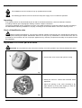
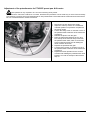
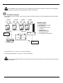
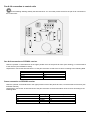
37+6883
MANUALE D’USO
__________________________
OPERATING INSTRUCTIONS
__________________________
MANUEL D’INSTRUCTIONS
__________________________
BEDIENUNGSANWEISUNG
PTH355P
MANUALE
D’USO
INDICE
INDICE ....................................................................................................................................................................................1
INTRODUZIONE .....................................................................................................................................................................2
Contenuto dell’imballo ............................................................................................................................................................................... 2
Cosa contiene questo manuale ................................................................................................................................................................. 2
Convenzioni tipografiche ........................................................................................................................................................................... 2
NORME DI SICUREZZA.........................................................................................................................................................2
DATI DI MARCATURA ...........................................................................................................................................................3
DESCRIZIONE DEL BRANDEGGIO PTH355P .....................................................................................................................3
Caratteristiche ........................................................................................................................................................................................... 3
Apparecchi compatibili............................................................................................................................................................................... 3
INSTALLAZIONE ....................................................................................................................................................................4
Apertura dell’imballaggio ........................................................................................................................................................................... 4
Controllo della marcatura .......................................................................................................................................................................... 4
REGOLAZIONE DEL BRANDEGGIO PTH355P....................................................................................................................4
Regolazione del potenziometro per il brandeggio PTH355P..................................................................................................................... 5
CONNETTORI E COLLEGAMENTI .......................................................................................................................................6
Esempio di installazione ............................................................................................................................................................................ 6
Collegamento del brandeggio alle unità di comando................................................................................................................................. 7
Collegamento del brandeggio al ricevitore DTRXDC ............................................................................................................................ 7
Collegamento del Preset al ricevitore DTRXDC ................................................................................................................................... 7
ACCENSIONE E SPEGNIMENTO..........................................................................................................................................8
MANUTENZIONE....................................................................................................................................................................8
RISOLUZIONE DI PROBLEMI ...............................................................................................................................................8
CARATTERISTICHE TECNICHE ...........................................................................................................................................9
Meccanica.................................................................................................................................................................................................. 9
Generali ..................................................................................................................................................................................................... 9
Caratteristiche elettriche............................................................................................................................................................................ 9
Dimensioni................................................................................................................................................................................................. 9
Il produttore declina ogni responsabilità per eventuali danni derivanti da un uso improprio delle
apparecchiature menzionate in questo manuale; si riserva inoltre il diritto di modificarne il contenuto
senza preavviso.
Ogni cura é stata posta nella raccolta e nella verifica della documentazione contenuta in questo
manuale: tuttavia il produttore non può assumersi alcuna responsabilità derivante dall’utilizzo della
stessa. Lo stesso dicasi per ogni persona o società coinvolta nella creazione e nella produzione di
questo manuale.
Pag. 1
PTH355P 3201
Introduzione
Contenuto dell’imballo
• 1 brandeggio PTH355P
• 1 staffa per supporto telecamera
• 1 sacchetto dotazione viteria
• 1 manuale d’uso
Alla consegna del prodotto verificare che l’imballo sia integro e non abbia segni evidenti di cadute o abrasioni. In caso
di evidenti segni di danno all’imballo contattare immediatamente il fornitore.
Controllare che il contenuto sia rispondente alla lista del materiale sopra indicata.
Cosa contiene questo manuale
In questo manuale è descritto il brandeggio PTH355P, con le particolari procedure di installazione, configurazione e
utilizzo. E’ necessario leggere attentamente questo manuale, in particolar modo il capitolo concernente le norme di
sicurezza, prima di installare ed utilizzare il brandeggio.
Convenzioni tipografiche
Nel presente manuale si fa uso di diversi simboli grafici, il cui significato è riassunto di seguito:
Rischio di scariche elettriche; togliere l’alimentazione prima di procedere con le operazioni, se non é
espressamente indicato il contrario.
L’operazione é molto importante per il corretto funzionamento del sistema: si prega di leggere attentamente la
procedura indicata, ed eseguirla secondo le modalità previste.
Descrizione delle caratteristiche del sistema: si consiglia di leggere attentamente per comprendere le fasi
successive.
Norme di sicurezza
Il brandeggio PTH355P e’ conforme alle normative vigenti all’atto della pubblicazione del presente manuale per
quanto concerne la sicurezza elettrica, la compatibilità elettromagnetica ed i requisiti generali.
Si desidera tuttavia garantire gli utilizzatori (tecnico installatore e operatore) specificando alcune avvertenze per
operare nella massima sicurezza:
• L’installazione dell’apparecchio (e dell’intero impianto di cui esso fa parte) deve essere effettuata da personale
tecnico adeguatamente qualificato
• L’apparecchio deve essere aperto soltanto da personale tecnico qualificato. La manomissione dell’apparecchio fa
decadere i termini di garanzia
• Collegare ad un dispositivo corrispondente come indicato sulle etichette di marcatura (vedere il successivo capitolo
Dati di marcatura)
• Prima di spostare o effettuare interventi tecnici sull’apparecchio, disinserire i cavi di collegamento con altri
dispositivi
• Non utilizzare cavi di tensione con segni di usura o invecchiamento, in quanto rappresentano un grave pericolo per
l’incolumità degli utilizzatori
• Non utilizzare l’apparecchio in presenza di sostanze infiammabili
• Non permettere l’uso dell’apparecchio a bambini o incapaci
• Accertarsi che l’apparecchio sia fissato in maniera solida e affidabile
• L’apparecchio si considera disattivato soltanto quando i cavi di collegamento con altri dispositivi sono stati rimossi
• Per l’assistenza tecnica rivolgersi esclusivamente al personale tecnico autorizzato
• Conservare con cura il presente manuale per ogni futura consultazione
Pag. 2
PTH355P 3201
Dati di marcatura
Sul brandeggio PTH355P sono riportate due etichette conformi alla marcatura CE.
La prima etichetta contiene:
• Codice di identificazione del modello (Codice a barre Extended 3/9 )
• Tensione di alimentazione (Volt)
• Frequenza (Hertz)
• Consumo (Watt)
La seconda etichetta indica il numero di serie del modello (codice a barre Extended 3/9)
All’atto dell’installazione controllare che le caratteristiche di alimentazione del brandeggio corrispondano a quelle
richieste. L’uso di apparecchi non idonei può portare a gravi pericoli per la sicurezza del personale e dell’impianto.
Descrizione del brandeggio PTH355P
L’unità PTH355P è un brandeggio verticale e orizzontale appositamente studiato per essere utilizzato in
ambienti esterni. Il preset è di serie.
Caratteristiche
•
•
•
•
•
•
•
Movimento sul piano orizzontale (Pan): da 0 a 345°. Velocità: 30° al secondo
Movimento sul piano verticale (Tilt): da 0 a 360°. Velocità: 18° al secondo
Costruzione in fusione di alluminio con trattamento anticorrosione
Chiusura completamente sigillata per operare sia in ambiente interno che esterno
Temperatura di funzionamento da -20°C a 50°C (da -4°F a 122°F)
Alimentazione 24V Ù
PRESET
Apparecchi compatibili
La funzionalita’ del brandeggio e’ garantita solo se collegati a :
•
Ricevitore di comandi DTRXDC: ricevitore digitale, controllato da un microprocessore, per la gestione a distanza
di un brandeggio a velocità variabile ed ottiche motorizzate. La connessione all’unità di controllo può essere
eseguita in RS232 o in RS485 (in questo caso, la distanza di connessione può raggiungere 1200m). Il DTRXDC,
controllato dalla tastiera DCS3, può richiamare fino a 14 posizioni preset di brandeggio ed ottiche con 4 allarmi
locali. Sono disponibili 2 relais di controllo ausiliari per la gestione, ad esempio, dell’accensione e spegnimento di
un illuminatore IR, tramite il contatto di potenza. Una scatola stagna IP65 assicura protezione contro tutti gli agenti
atmosferici.
Sei pressacavi PG11 ne facilitano la connessione.
Pag. 3
PTH355P 3201
Installazione
La fase di installazione deve essere effettuata solo da personale tecnico qualificato.
Le seguenti procedure sono da effettuare in assenza di alimentazione, se non diversamente indicato.
Apertura dell’imballaggio
Se l’imballo non presenta evidenti difetti (dovuti a cadute o abrasioni anomale), procedere al controllo del materiale in
esso contenuto, secondo la lista fornita al paragrafo Contenuto dell’imballo al capitolo Introduzione.
I materiali d’imballo sono costituiti interamente da materiale riciclabile. Sarà cura del tecnico installatore smaltirli
secondo le modalità di raccolta differenziata o comunque secondo le norme vigenti nel Paese di utilizzo.
Controllo della marcatura
Prima di procedere con l’installazione controllare che il materiale fornito corrisponda alle specifiche richieste,
esaminando le etichette di marcatura, secondo quanto descritto al capitolo Dati di marcatura.
Non effettuare per nessun motivo alterazioni o collegamenti non previsti in questo manuale: l’uso di apparecchi non
idonei può portare a gravi pericoli per la sicurezza del personale e dell’impianto.
Regolazione del brandeggio PTH355P
ATTENZIONE: Non posizionare il brandeggio manualmente poichè questa operazione può danneggiare
seriamente gli ingranaggi.
• Svitare le viti del coperchio e aprire la
scatola
Fig.1
• Identificare le camme per la regolazione
della corsa verticale e di quella orizzontale
• Regolare l’ampiezza di apertura delle
camme secondo l’angolo desiderato,
forzandole leggermente (non servono
attrezzi, il movimento è a frizione)
Fig.2
Pag. 4
PTH355P 3201
Regolazione del potenziometro per il brandeggio PTH355P
Questa funzione e’ molto importante per il corretto funzionamento del preset.
La seguente procedura deve essere eseguita sia per il potenziometro collegato al movimento orizzontale che per
quello collegato al movimento verticale.
Il brandeggio e’ già regolato in fabbrica , dunque tale procedura dovra’ essere effettua solo in caso di effettiva
necessita’.
1. Disconnettere l’alimentazione del brandeggio.
2. Regolare le camme con l’aiuto di un
cacciavite fino a renderne simmetrica la
posizione rispetto al fine corsa.
3. Allentare la vite di fissaggio A ed il dado B
della barra porta potenziometro del
movimento orizzontale
4. Disimpegnare il pignone dalla ruota dentata.
5. Posizionare un Ohmetro tra i morsetti Vcc e
Pan della morsettiera J4, girare l’alberino del
potenziometro collegato al movimento
orizzontale fino a leggere un valore di 1875
Ohm circa.
6. Riposizionare l’ingranaggio del
potenziometro.
7. Bloccare la vite di fissaggio A ed il dado B
della barra porta potenziometro del
movimento orizzontale
8. Ripetere la stessa operazione per il
movimento verticale leggendo il valore del
potenziometro tra i morsetti Vcc e Tilt della
morsettiera J4.
Pag. 5
PTH355P 3201
Connettori e collegamenti
La procedura di installazione deve essere effettuata soltanto da personale tecnico qualificato: il collegamento
non corretto delle varie periferiche può comportare l’isolamento della tastiera dal resto del sistema.
Esempio di installazione
Un operatore con più monitor, con controllo di una serie di brandeggi in configurazione mista (a stella e in cascata)
PTH355P
DTRXDC
PTH355P
DTRXDC
PTH355P
PTH355P
DTRXDC
MATERIALE IMPIEGATO
Tastiera di controllo:
• 1 tastiera di controllo DCS3
Gestione del video:
• 1 commutatore video SW328
• 2 monitor
• 4 telecamere
Gestione della telemetria:
• 4 ricevitori DTRXDC
• 4 brandeggi PTH355P
DTRXDC
Cavo 2 fili
SW328
DCS3
Cavo 2 fili
2
Collegamento motori-brandeggio: 4 x 0,56mm (AWG 20)
2
Collegamento potenziometri-preset: 4 x 0,34 mm (AWG 22)
E’ necessario utilizzare due cavi diversi per il controllo dei motori e per il collegamento con i potenziometri del
preset.
Pag. 6
PTH355P 3201
Collegamento del brandeggio alle unità di comando
Nella figura seguente identificare la morsettiera J1 per il collegamento del brandeggio alle unità di comando:
Collegamento del brandeggio al ricevitore DTRXDC
Dove Agire: morsettiera J1 sulla scheda superiore del brandeggio (vedi figura), morsettiera J1 del ricevitore (vedi
manuale DTRXDC)
Impostazioni: collegare la morsettiera J1 del brandeggio a quella del ricevitore secondo la tabella seguente
Morsetto J1 del DTRXDC
Morsetto J1 (brandeggio)
PAN+
PANTILT+
TILT-
PAN+
PANTILT+
TILT-
Collegamento del Preset al ricevitore DTRXDC
Dove Agire: morsettiera J4 sulla scheda superiore del brandeggio, morsettiera J3 del ricevitore (vedi manuale
DTRXDC)
Impostazioni: collegare la morsettiera J4 in uscita dal brandeggio a quella del ricevitore secondo la tabella seguente
Morsetto J3 del DTRXDC
Significato
Morsetto J4 sul brandeggio
VCC
PAN
TILT
GND
+5 Volt
Orizzontale
Verticale
0 Volt
Vcc
Pan
Tilt
Gnd
Pag. 7
PTH355P 3201
Accensione e spegnimento
Prima di fornire alimentazione:
• controllare che il materiale fornito corrisponda alle specifiche richieste, esaminando le etichette di marcatura,
secondo quanto descritto al capitolo Descrizione della marcatura.
• controllare che il brandeggio PTH355P e gli altri componenti dell’impianto siano chiusi e sia quindi impossibile il contatto diretto con parti in tensione.
• accertarsi che tutte le parti siano fissate in maniera solida ed affidabile
• controllare che le fonti di alimentazione ed i cavi di collegamento siano in grado di sopportare il consumo del
sistema
Manutenzione
Il brandeggio PTH355P non necessita di particolare manutenzione.
Si raccomanda di fissarlo saldamente ad una una base solida, con i cavi di alimentazione e di collegamento in
posizione tale da non essere causa di intralcio all’operatore.
Risoluzione di problemi
Il brandeggio PTH355P é caratterizzato da una notevole facilità d’uso, ma cio’ nonostante possono insorgere dei
problemi sia in fase di installazione o durante l’uso.
Problema
Possibile causa
La tastiera di comando o il Collegamenti errati
ricevitore funzionano, ma il
brandeggio non risponde
La tensione fornita dall’unità di
comando non è quella richiesta
dal brandeggio
Collegamenti errati
Il brandeggio risponde ai
comandi del ricevitore
DTRXDC ma il PRESET
non funziona
Pag. 8
Intervento correttivo
Controllare i collegamenti tra brandeggio e
unità di comando
Controllare i dati di marcatura dell’unità di
comando e del brandeggio
Controllare i collegamenti tra brandeggio ed il
ricevitore DTRXDC
PTH355P 3201
Caratteristiche tecniche
Meccanica
Pan
Velocità
Coppia
Tilt
Velocità
Coppia
Carico massimo
Protezione
Potenziometro
0-345° movimento nel piano orizzontale
30° al secondo
6 Nm al voltaggio specificato
0-360° movimento nel piano verticale
18° al secondo
6 Nm al voltaggio specificato
12 Kg (26 lb) - (bilanciato)
IP 66
Lineare 5KOhm multigiro (10 giri)
Generali
Costruzione
Finitura
Posiz. montaggio
Temperatura
Dimensioni
Peso
Diametro cavo
Fusione di alluminio;
Verniciatura RAL9002 con polveri epossidiche
normale/rovescia
da -20°C a +50°C (da -4°F a 122°F)
180x166x145 mm (L x H x P)
3.5 Kg (8 lb)
10 mm
Caratteristiche elettriche
Alimentazione
24V Ùý 11+11W
Dimensioni
Pag. 9
PTH355P 3201
37+6883
OPERATING
INSTRUCTIONS
INDEX
INDEX......................................................................................................................................................................................1
INTRODUCTION.....................................................................................................................................................................2
Packing contents ....................................................................................................................................................................................... 2
Contents of this Manual ............................................................................................................................................................................. 2
Typographic conventions........................................................................................................................................................................... 2
SAFETY RULES .....................................................................................................................................................................2
IDENTIFICATION DATA.........................................................................................................................................................3
DESCRIPTION OF PTH355P PAN & TILT MOTOR..............................................................................................................3
Features .................................................................................................................................................................................................... 3
Appliances compatible with PTH355P....................................................................................................................................................... 3
INSTALLATION ......................................................................................................................................................................4
Unpacking.................................................................................................................................................................................................. 4
Check of identification data ....................................................................................................................................................................... 4
ADJUSTMENT OF PTH355P PAN & TILT MOTOR..............................................................................................................4
Adjustment of the potentiometer for PTH355P preset pan & tilt motor...................................................................................................... 5
CONNECTORS AND CONNECTIONS ..................................................................................................................................6
Installation example ................................................................................................................................................................................... 6
Pan & tilt connection to control units ......................................................................................................................................................... 7
Pan & tilt connection to DTRXDC receiver ............................................................................................................................................ 7
Preset connection to DTRXDC receiver ................................................................................................................................................ 7
SWITCHING ON AND OFF ....................................................................................................................................................8
MAINTENANCE ......................................................................................................................................................................8
PROBLEM SOLUTION...........................................................................................................................................................8
SPECIFICATIONS ..................................................................................................................................................................9
Mechanics.................................................................................................................................................................................................. 9
General ...................................................................................................................................................................................................... 9
Electric features ......................................................................................................................................................................................... 9
Dimensions ................................................................................................................................................................................................ 9
The manufacturer declines all responsibility for any damage caused by an improper use of the
appliances mentioned in this manual; furthermore, the manufacturer reserves the right to modify its
contents without any prior notice.
The documentation contained in this manual has been collected with great care: the manufacturer,
however, cannot take any liability for its use. The same thing can be said for any person or company
involved in the creation and production of this manual.
Pag. 1
PTH355P 3201
Introduction
Packing contents
• 1 pan & tilt motor PTH355P
• 1 bracket for camera
• 1 bag with bolts and screws
• 1 instruction manual
After the delivery, check that the packing is not damaged and shows no evident signs of falls or abrasions. Should this
be so, contact immediately the supplier.
Check that the contents correspond to the above-mentioned list of materials.
Contents of this Manual
This manual describes PTH355P pan & tilt motor, together with their specific procedures of installation, configuration
and use. Read this manual carefully, in particular the chapter concerning the safety rules, before installing and
using the pan & tilt motor.
Typographic conventions
Different graphic symbols are used in this manual, the meaning of which is here described:
Hazard of electric shock; disconnect the power supply before proceeding, if not otherwise specified.
The operation is very important for the correct working of the system: read carefully the procedure indicated,
and carry it out according to the required modalities.
Description of system features: read carefully to understand the following phases.
Safety rules
PTH355P pan & tilt motor complies with the normative laws in force at the time of editing of this manual,
concerning electric safety, electromagnetic compatibility and general requirements.
Anyway, in order to ensure the users (installer technician and operator), the following warnings are specified for
safety’s sake:
• The appliance (and the complete system, which it belongs to) must be installed only by qualified technical staff
• The appliance must be opened only by qualified technical staff. The tampering of the appliance may void the
guarantee terms.
• Connect to a device corresponding to the specifications indicated on the data plate (see next chapter Identification
data)
• Before any shifting or technical operations on the appliance, the cables connected to other appliances have been
removed
• Do not use voltage cables showing wear or ageing, since they may seriously compromise the users’ safety
• Do not use the appliance in the presence of inflammable substances
• Do not allow children or people not familiar with the appliance to use it
• Make sure the appliance is fixed in a solid and reliable way
• The appliance is completely off-line only when the cables connected to other appliances have been removed
• For after-sale service call only authorised technical staff
• Keep this manual close to hand for any future reference
Pag. 2
PTH355P 3201
Identification data
On PTH355P pan & tilt motor there are two plates complying with EC specifications.
The first plate includes:
• Model identification code (Extended bar code 3/9 )
• Mains voltage (Volt)
• Frequency (Hertz)
• Power consumption (Watt)
The second plate shows the model serial number (Extended bar code 3/9)
When installing the appliance, check that the power supply specifications of the pan & tilt motor correspond to those
required. The use of improper appliances may seriously compromise the safety of the personnel and the installation.
Description of PTH355P pan & tilt motor
PTH355P unit is a vertical and horizontal pan & tilt motor, expressly projected for outdoor installations.
The PRESET is delivered as standard.
Features
•
•
•
•
•
•
•
Horizontal movement (Pan): from 0 to 345°. Speed: 30° per second
Vertical movement (Tilt): from 0 to 360°. Speed: 18° per second
Construction in corrosion-proof die-cast aluminium
Completely sealed closing for indoor/outdoor operation
Operating temperature from -20°C to +50°C (from -4°F to 122°F)
PTH355P power supply: 24V Ù
PRESET
Appliances compatible with PTH355P
The working of pan & Tilt motors ist guarrated only if connected to:
• DTRXDC control receiver: digital receiver, controlled by a microprocessor, for remote control of a variable speed
Pan & Tilt (PTH355P) and a motor-driven zoom lens. The connection to the control unit can be carried out in
RS232 or in RS485 (in this case, the connection distance can reach 1200m). This digital receiver is controlled by
the DCS3 keyboard and it is possible to recall up to 14 Pan & Tilt and optics preset positions with 4 local alarms.
Two auxiliary control relays are available for controlling, for instance, the switching on and off of a IR illuminator,
through a power contact. A IP65 weatherproof box ensures protection against all weather conditions.
6 PG11 cable glands make connection easier.
Pag. 3
PTH355P 3201
Installation
The installation must be carried out only by qualified technical staff.
The following procedures must be carried out with power supply off, if not otherwise specified.
Unpacking
If the packing shows no relevant defects (due to falls or anomalous abrasions), check the material contained,
according to the list given at paragraph Packing contents chapter Introduction.
The packing materials can be completely recycled. The installer technician is required to dispose of them according to
the differentiated collecting modalities or ,anyway, according to the normative laws in force in the Country of use.
Check of identification data
Before installing the appliance, check that the material supplied corresponds to the specifications indicated on
the data plate, following the chapter Identification data. Do not carry out any modification or connections which are not
provided for in this manual: the use of improper appliances may seriously compromise the safety of the personnel and
the installation.
Adjustment of PTH355P pan & tilt motor
CAUTION: Do not position the pan & tilt motor manually, since this operation may seriously damage the gears.
• Unscrew the cover screws and open the casing
Fig.1
• Identify the cams for vertical and horizontal stroke
adjustment
• Adjust the opening of the cams according to the
angle wished, by forcing them slightly (no tools are
necessary, it is a friction movement)
Fig.2
Pag. 4
PTH355P 3201
Adjustment of the potentiometer for PTH355P preset pan & tilt motor
This operation is very important for the correct working of the preset.
PTH355P Pan & Tilt motor is still set in our works, therefore this procedure is to be made only in case of real necessity.
The following procedure has to be followed both for the potentiometer connected with the horizontal movement and for
the one connected with the vertical movement.
1. Disconnect the pan & tilt motor supply
2. Adjust the cams by means of a screwdriver
until their position is symmetric compared to
the end of stroke
3. Loosen the fixing screw “A” and the nut “B” of
the potentiometer holder bar of the horizontal
movement
4. Release the pinion from the gear
5. Place an Ohmmeter between the Vcc and
Pan clamps of the terminal strip J4 and turn
the potentiometer shaft, which is connected
to the horizontal movement, till reading the
value of about 1875 Ohm.
6. Replace the potentiometer gear
7. Lock the fixing screws “A” and the nut “B” of
the potentiometer holder bar of the horizontal
movement
8. Repeat the same operation for the vertical
movement till reading the potentiometer value
between Vcc and Tilt clamps of the terminal
strip J4.
Pag. 5
PTH355P 3201
Connectors and connections
The installation must be carried out only by qualified technical staff: an improper connection of the peripheral
units may cause the keyboard to be isolated from the rest of the system.
Installation example
One operator with more monitors, who controls a series of pan & tilt motors in mixed configuration (star and cascade
connection)
PTH355P
DTRXDC
PTH355P
DTRXDC
PTH355P
DTRXDC
PTH355P
MATERIAL USED
Control keyboard:
• 1 DCS3 control keyboard
Video handling:
• 1 SW328 video switcher
• 2 monitors
• 4 telecameras
• Telemetry handling:
• 4 DTRXDC receivers
• 4 PTH355P pan & tilt motors
DTRXDC
SW328
Cable with 2
wires
DCS3
Cable with 2
wires
2
Connection Pan & Tilt – motors: 4 x 0,56 mm (AWG 20)
2
Connection potentiometers – preset: 4 x 0,34 mm (AWG 22)
The use of two different cables will be necessary for the control of the motors and for the connection with the
preset potentiometers.
Pag. 6
PTH355P 3201
Pan & tilt connection to control units
In the following drawing, identify the terminal block J1 in the lower printed circuit for the pan & tilt connection to
the control units:
Pan & tilt connection to DTRXDC receiver
Where to operate: J1 terminal block in the upper printed circuit of the pan & tilt motor (see drawing), J1 terminal block
of the receiver (see DTRXDC manual)
Adjustments: connect the terminal block J1 of the pan & tilt motor to that of the receiver according to the following table
Terminal block J1 of DTRXDC Terminal block J1 (Pan & Tilt)
PAN +
PAN TILT +
TILT -
Pan +
Pan Tilt +
Tilt -
Preset connection to DTRXDC receiver
Where to operate: J4 terminal block in the upper printed circuit of the pan & tilt motor, J3 terminal block of receiver (see
DTRXDC manual)
Adjustments: connect the J4 terminal block of the pan & tilt motor to the terminal block of the receiver according to the
following table:
Terminal block J3 of DTRXDC
Vcc
Pan
Tilt
Gnd
Meaning
+5 Volt
Horizontal
Vertical
0 Volt
Terminal block J4 (Pan & Tilt)
Vcc
Pan
Tilt
Gnd
Pag. 7
PTH355P 3201
Switching on and off
Before connecting the appliance:
• check that the material supplied corresponds to the specifications indicated on the data plate, following the chapter
Identification data
• check that PTH355P pan & tilt motor and the other components of the installation are closed in order to avoid direct
contact with energized parts.
• make sure that all the parts are fixed in a solid and reliable way
• check that the electrical capacity and the connection cables will support the system power consumption
Maintenance
PTH355P pan & tilt motor does not need a special maintenance.
Make sure they always rest on a solid base, and that the power supply and connection cables do not hinder the
operator.
Problem solution
Even if PTH355P pan & tilt motor is very easy to use, some problems may arise during installation, configuration or
use.
Problem
Possible cause
The control keyboard or the Incorrect connections
receiver are working, but the
pan & tilt motor does not
respond
The voltage supplied by the
control unit is different from that
required by the pan & tilt motor
Incorrect connections
The pan & tilt motor
responds to the controls of
DTRXDC receiver but the
PRESET does not work
Pag. 8
Remedy
Check the connections between the pan & tilt
motor and the control unit
Check the identification data of the control
unit and of the pan & tilt motor
Check the connections between the pan & tilt
motor and DTRXDC receiver
PTH355P 3201
Specifications
Mechanics
Pan
Speed
Torque
Tilt
Speed
Torque
Maximum load
Protection
Potentiometer
0-345° horizontal plane movement
30° per second
6 Nm at specified voltage
0-360° vertical plane movement
18° per second
6 Nm at specified voltage
12 Kg (26 lb) (balanced)
IP 66
Linear 5Kohm Multiturns (10 turns)
General
Construction
Finish
Mounting pos.
Temperature
Dimensions
Weight
Cable diameter
Aluminium die-cast
RAL9002 epoxy coat
normal/reverse
from -20°C to +50°C (from -4°F to 122°F)
180x166x145 mm (
3,5 Kg (8 lb)
10 mm
Electric features
Power Supply
24V Ù 11 + 11W
Dimensions
Pag. 9
PTH355P 3201
37+6883
MANUEL
D’INSTRUCTIONS
INDEX
INDEX......................................................................................................................................................................................1
INTRODUCTION.....................................................................................................................................................................2
Contenu de l’emballage............................................................................................................................................................................. 2
Contenu de ce manuel .............................................................................................................................................................................. 2
Conventions typographiques ..................................................................................................................................................................... 2
NORMES DE SÉCURITÉ .......................................................................................................................................................2
CARACTÉRISTIQUES TECHNIQUES ...................................................................................................................................3
DESCRIPTION DE LA TOURELLE PTH355P ......................................................................................................................3
Caractéristiques......................................................................................................................................................................................... 3
Appareils compatibles ............................................................................................................................................................................... 3
INSTALLATION ......................................................................................................................................................................4
Déballage .................................................................................................................................................................................................. 4
Contrôle des caractéristiques techniques.................................................................................................................................................. 4
RÉGLAGE DE LA TOURELLE PTH355P ..............................................................................................................................4
Réglage du potentiomètre pour la tourelle avec préselection PTH355P ................................................................................................... 5
CONNECTEURS ET RACCORDEMENTS.............................................................................................................................6
Exemple d’installation ................................................................................................................................................................................ 6
Pour le contrôle des moteurs et pour la connexion avec les potentiomètres du preset il est nécessaire d’utiliser deux câbles différents.6
Raccordement de la tourelle aux unités de commande............................................................................................................................. 7
Raccordement de la tourelle au récepteur DTRXDC............................................................................................................................. 7
Raccordement de la Préselection au récepteur DTRXDC..................................................................................................................... 7
ALLUMAGE ET COUPURE....................................................................................................................................................8
ENTRETIEN ............................................................................................................................................................................8
RÉSOLUTION DES PROBLÈMES.........................................................................................................................................8
DONNÉES TECHNIQUES ......................................................................................................................................................9
Mécanique ................................................................................................................................................................................................. 9
Données générales ................................................................................................................................................................................... 9
Données électriques .................................................................................................................................................................................. 9
Dimensions ................................................................................................................................................................................................ 9
Le producteur décline toute responsabilité pour les dommages éventuels dus à une utilisation non
appropriée des appareils mentionnés dans ce manuel; on réserve en outre le droit d’en modifier le
contenu sans préavis. La documentation contenue dans ce manuel a été rassemblée et vérifiée
avec le plus grand soin: cependant, le producteur ne peut pas s’assumer aucune responsabilité
dérivante de l’emploi de celle-là. La même chose vaut pour chaque personne ou société impliquées
dans la création et la production de ce manuel.
Pag. 1
PTH355P 3201
Introduction
Contenu de l’emballage
• 1 tourelle PTH355P
• 1 support caméra
• 1 sachet de vis
• 1 manuel d’emploi
Lors de la livraison du produit, vérifier si l’emballage est correct et s’il n’a pas subi des signes évidents de chutes ou de
choc. Si l’emballage présente des signes évidents de dommage, contacter immédiatement le transporteur. Vérifier que
le contenu correspond à la liste du matériel indiqué ci-dessus.
Contenu de ce manuel
Dans ce manuel on décrit la tourelle PTH355P et les procédures particulières d’installation, configuration et emploi. Il
est nécessaire de lire attentivement ce manuel, surtout le chapitre concernant les normes de sécurité, avant
d’installer et employer la tourelle.
Conventions typographiques
Dans ce manuel on emploie des symboles graphiques différents, dont le sens est résumé ci-dessous:
Risque de décharge électrique; couper l’alimentation avant de procéder avec toute opération, si le contraire
n’est pas expressément indiqué.
L’opération est très importante pour le fonctionnement correct du système: lire attentivement la procédure
indiquée, et l’exécuter suivant les modalités prévues.
Description des caractéristiques du système: lire attentivement pour comprendre les phases suivantes.
Normes de sécurité
La tourelle PTH355P est conforme aux normes en vigueur au moment de la publication de ce manuel pour ce
qui concerne la sécurité électrique, la compatibilité électromagnétique et les conditions requises générales.
On désire toutefois garantir les utilisateurs (technicien installateur et opérateur) en précisant certaines instructions pour
opérer en toute sécurité:
• L’installation de l’appareil (et du système complet dont il fait partie) doit être effectuée par une personne qualifiée du
point de vue technique.
• L’appareil doit être ouvert seulement par un personnel technique qualifié. L’altération de l’appareil fait déchoir les
termes de garantie
• Raccorder à un appareil en suivant les indications des plaques des caractéristiques techniques (voir le chapitre
suivant Caractéristiques techniques )
• Avant de déplacer ou effectuer des interventions techniques sur l’appareil, débrancher les câbles de raccordement
avec d’autres dispositifs.
• Ne pas employer de câbles de tension avec signes d’usure ou vieillissement, parce qu’ils peuvent compromettre
sérieusement la sécurité des utilisateurs.
• Ne pas employer l’appareil en présence de substances inflammables
• Ne pas laisser des enfants ou des personnes non qualifiées utiliser l’appareil
• Vérifier si l’appareil est fixé de façon solide et fiable
• L’appareil est désactivé seulement quand les câbles de raccordement avec d’autres dispositifs ont été enlevés.
• Pour le service après-vente s’adresser exclusivement à personnel technique autorisé.
• Conserver soigneusement ce manuel pour toute consultation ultérieure
Pag. 2
PTH355P 3201
Caractéristiques techniques
Sur la tourelle PTH355P il y a deux plaques conformes aux caractéristiques techniques CE.
La première plaque contient:
• Code d’identification du modèle (Code à barre EXT3/9 )
• Tension d’alimentation (Volt)
• Fréquence (Hertz)
• Max. consommation (Watt)
La deuxième plaque indique le numéro de série du modèle (Code à barre EXT3/9)
Lors de l’installation vérifier que les caractéristiques d’alimentation de la tourelle correspondent aux caractéristiques
requises. L’emploi d’appareils non appropriés peut compromettre sérieusement la sécurité du personnel et de
l’installation.
Description de la tourelle PTH355P
L’unité PTH355P est une tourelle verticale et horizontale, spécialement conçue pour être employée à
l’extérieur. Le preset (préselection) est fourni en dotation.
Caractéristiques
•
•
•
•
•
•
•
Mouvement horizontal ( Pan ): de 0 à 345°. Vitesse: 30° / sec
Mouvement vertical ( Tilt ): de 0 à 360°. Vitesse: 18° / sec
Construction en fonte d’aluminium avec traitement anticorrosion
Fermeture complètement scellée pour installations intérieures et extérieures
Température de fonctionnement de -20°C à +50°C ( de -4°F à 122°F )
Alimentation: 24V Ù
PRÉSELECTION (preset)
Appareils compatibles
• Récepteur de commandes DTRXDC: récepteur digital, controllè par microprocesseur, pour la géstion à distance
des tourelles à vitesse variable et zooms motorisés. La connexion à l’unité de contrôle peut être effectuée en
RS232 ou en RS485 (dans ce cas là, la distance de connexion peut rejoindre 1200m), Le DTRXDC, controllé par le
pupitre DCS3, peut rappeler 14 positions de preset de la tourelle et des zooms motorisés avec 4 alarmes locals.
Deux relays auxiliaires de contrôle sont disponibles pour la gestion, par exemple, de l’allumage et coupure d’un
projecteur IR, par le contact de puissance. Une boîte avec étanchéité IP65 assure une protection contre tous les
agents atmosphériques.
Six presse-étoupes PG11 en facilitent la connexion.
Pag. 3
PTH355P 3201
Installation
L’installation doit être effectuée seulement par un technicien qualifié.
Les procédures suivantes sont effectuées hors tension, sauf avis contraire.
Déballage
Si l’emballage ne présente pas d’évidents défauts dus à des chutes ou des chocs anormaux, procéder au contrôle du
matériel contenu, suivant la liste fournie au chapitre Introduction, Contenu de l’emballage.
L’emballage est entièrement fait de matériel recyclable. Le technicien installateur devra l’éliminer selon les modalités
de recolte diversifiée ou en tout cas suivant les normes en vigueur dans le Pays d’emploi.
Contrôle des caractéristiques techniques
Avant d’installer l’appareil, vérifier que les caractéristiques techniques du matériel fourni, figurant sur les
plaques, correspondent aux spécifications requises, en se rapportant au chapitre Caractéristiques techniques . Ne
jamais effectuer de modifications ou de raccordements non prévus dans ce manuel: l’emploi d’appareils non
appropriés peut compromettre sérieusement la sécurité des personnes et de l’installation.
Réglage de la tourelle PTH355P
ATTENTION: Ne pas forcer manellement l’orientation horizontale ou verticale sous peine de deteriorer le
mecanisme de la tourelle et annuler la garantie.
• Dévisser les vis du couvercle et ouvrir le boîtier
Fig.1
• Identifier les cames pour le réglage de la course
verticale et horizontale
• Régler l’ouverture des cames selon l’angle désiré, en
les forçant légèrement (il n’y a pas besoin d’outils,
c’est un mouvement à friction)
IMPORTANT : ne jamais desserrer les boulons de
blocage des cames.
Fig.2
Pag. 4
PTH355P 3201
Réglage du potentiomètre pour la tourelle avec préselection PTH355P
Cette opération est très importante pour le correct fonctionnement de la préselection.
Le réglage doit être systématiquement effectué pour le potentiométre horizontal et pour le potentiometre vertical.
Le non respect de cette procedure entraine la destruction du potentiometre.
La tourelle est déjà régulièe en usine, dont telle procédure doit être effectuée seulement en cas de effective nécessité.
1. Couper l’alimentation de la tourelle
2. Régler les cames avec un tournevis jusqu’à
rendre la position symétrique par rapport au
switch fin de course
3. Relâcher la vis de fixage “A” et de l’écrou “B”
de la barre porte-potentiomètre du
mouvement horizontal
4. Désengager le pignon de la roue dentée
5. Placer un Ohmmètre entre les bornes Vcc et
Pan du serre-câbles J4 et tourner l’arbre du
potentiomètre, connecté au mouvement
horizontal, jusqu’à lire la valeur d’environ
1875 Ohm.
6. Replacer l’engrenage du potentiomètre
7. Bloquer la vis de fixage “A” et de l’écrou “B”
de la barre porte-potentiomètre du
mouvement horizontal
8. Répéter la même opération pour le
mouvement vertical en lisant la valeur du
potentiomètre entre les bornes Vcc et Tilt du
serre-câbles J4.
Pag. 5
PTH355P 3201
Connecteurs et raccordements
La procédure d’installation doit être effectuée seulement par personnel technique qualifié: un raccordement
incorrect des différentes périphériques peut entraîner l’isolation du pupitre du reste du système.
Exemple d’installation
Un opérateur avec plusieurs moniteurs, qui contrôle une série de tourelles en configuration mixte (à étoile et en ligne
bus)
PTH355P
DTRXDC
PTH355P
DTRXDC
PTH355P
DTRXDC
PTH355P
MATERIEL EMPLOYÉ
Pupitre de contrôle:
• 1 pupitre DCS3
• Gestion du vidéo:
• 1 commutateur vidéo SW328
• 2 moniteurs
• 4 télécaméras
Gestion de la télémétrie:
• 4 récepteurs DTRXDC
• 4 tourelles PTH355P
DTRXDC
SW328
Câble avec 2
fils
DCS3
Câble avec 2
fils
2
Connexion moteurs – tourelles: 4 x 0,56 mm (AWG 20)
2
Connexion potentiomètres – preset: 4 x 0,34 mm (AWG 22)
Pour le contrôle des moteurs et pour la connexion avec les potentiomètres du preset il est nécessaire d’utiliser
deux câbles différents.
Pag. 6
PTH355P 3201
Raccordement de la tourelle aux unités de commande
Dans la figure suivante, identifier le bornier pour le raccordement de la tourelle aux unités de commande:
Raccordement de la tourelle au récepteur DTRXDC
Où l’on doit agir : plaque à bornes J1 sur la carte supérieure de la tourelle (voir figure), plaque à bornes J1 du
récepteur (voir manuel DTRXDC)
Réglages: raccorder la plaque à bornes J1 de la tourelle à celle du récepteur selon le tableau suivant
Borne J1 du DTRXDC
Borne J1 (tourelle)
PAN +
PAN –
TILT +
TILT -
Pan +
Pan Tilt +
Tilt -t
Raccordement de la Préselection au récepteur DTRXDC
Où l’on doit agir : plaque à bornes J4 sur la carte supérieure de la tourelle, plaque à bornes J3 du récepteur (voir
manuel DTRXDC)
Réglages: raccorder la plaque à bornes J4 en sortie de la tourelle à celle du récepteur DTRXDC selon le tableau
suivant
Borne J3 du DTRXDC
VCC
PAN
TILT
GND
Signifié
+5 Volt
Horizzontal
Vertical
0 Volt
Borne J4 sur la tourelle
Vcc
Pan
Tilt
Gnd
Pag. 7
PTH355P 3201
Allumage et coupure
Avant d’alimenter l’appareil:
• vérifier que le matériel fourni correspond aux spécifications requises, suivant les plaques des caractéristiques
techniques, en se rapportant au chapitre Caractéristiques techniques .
• vérifier si la tourelle PTH355P et les autres composantes de l’installation sont fermées afin d’éviter le contact direct
avec parties sous tension
• vérifier si toutes les parties sont fixées de façon solide et fiable
• vérifier si les sources d’alimentation et les câbles de raccordement sont aptes à supporter la consommation du
système
Entretien
La tourelle PTH355P n’a pas besoin d’un entretien particulier.
On recommande de l’appuyer sur une base solide, en faisant attention que les câbles d’alimentation et de
raccordement ne gênent pas l’opérateur.
Résolution des problèmes
Bien que la tourelle PTH355P se caractérise par une excellente fiabilité d’emploi, des problèmes peuvent se produire
en phase d’installation, de configuration ou pendant l’emploi.
Problème
Cause éventuelle
Le pupitre de commande ou Raccordements incorrects
le récepteur fonctionnent,
mais la tourelle ne repond
pas
La tension fournie par l’unité de
commande n’est pas celle
requise par la tourelle
Raccordements incorrects
La tourelle repond aux
commandes du récepteur
DTRXDC mais le preset ne
fonctionne pas
Solution
Contrôler les raccordements entre la tourelle et
l’unité de commande
Contrôler les caractéristiques techniques de
l’unité de commande et de la tourelle
Contrôler les raccordements entre la tourelle et
le récepteur DTRXDC
Pag. 8
PTH355P 3201
Données techniques
Mécanique
Pan
0-345° mouvement en horizontal
30° / seconde
6 Nm à la tension spécifiée
Tilt
0-360° mouvement en vertical
Vitesse
18° / seconde
Couple
6 Nm à la tension spécifiée
Charge maximum 12 Kg (26 lb) (balancé)
Protection
IP 66
Potentiomètre
Linéaire 5Kohm multirévolution (10 révolution)
Vitesse
Couple
Données générales
Construction
Finition
Posit. montage
Température
Dimensions
Poids
Diamètre câble
Fonte d’aluminium ; toutes les parties internes sont traitées anticorrosion
Vernissage RAL9002 à poudre époxyde
normale/à l’envers
de -20°C à +50°C (de -4°F à 122°F)
180x166x145 mm
3,5 Kg (8 lb)
10 mm
Données électriques
Alimentation
24V Ù 11 + 11W
Dimensions
Pag. 9
PTH355P 3201
37+6883
BEDIENUNGSANWEISUNG
INHALT
INHALT ...................................................................................................................................................................................1
EINLEITUNG...........................................................................................................................................................................2
Verpackungsinhalt ..................................................................................................................................................................................... 2
Inhalt dieses Bedienungshandbuches....................................................................................................................................................... 2
Typographische Symbole .......................................................................................................................................................................... 2
SICHERHEITSBESTIMMUNGEN ..........................................................................................................................................2
BETRIEBSEIGENSCHAFTEN AUF DEN DATENSCHILDERN ............................................................................................3
BESCHREIBUNG DER PTH355P-SCHWENKVORRICHTUNG ...........................................................................................3
Eigenschaften............................................................................................................................................................................................ 3
Kompatibeln Apparate ............................................................................................................................................................................... 3
INSTALLATION ......................................................................................................................................................................4
Öffnen der Verpackung.............................................................................................................................................................................. 4
Überprüfung der Betriebseigenschaften .................................................................................................................................................... 4
EINSTELLUNG DER PTH355P-SCHWENKVORRICHTUNG ..............................................................................................4
Einstellung des Potentiometers für die Schwenkvorrichtung mit Preset PTH355P ................................................................................... 5
VERBINDER UND ANSCHLÜSSE.........................................................................................................................................6
Installationsbeispiel ................................................................................................................................................................................... 6
Für die Motoren-Kontrolle und für die Verbindung mit den Potentiometern des Presets ist es nötig zwei verschiedene Kabel benutzen.6
Anschluß der Schwenkvorrichtung an den Bedienungseinheiten.............................................................................................................. 7
Anschluß der Schwenkvorrichtung am DTRXDC-Empfänger................................................................................................................ 7
Anschluß des Presets am DTRXDC-Empfänger ................................................................................................................................... 7
EINSCHALTEN UND AUSSCHALTEN ..................................................................................................................................8
WARTUNG..............................................................................................................................................................................8
PROBLEMLÖSUNG ...............................................................................................................................................................8
TECHNISCHE EIGENSCHAFTEN .........................................................................................................................................9
Mechanische Angaben .............................................................................................................................................................................. 9
Allgemeine Eigenschaften ......................................................................................................................................................................... 9
Elektrische Eigenschaften ......................................................................................................................................................................... 9
Dimensionen.............................................................................................................................................................................................. 9
Der Hersteller lehnt jede Haftung für eventuelle Schäden ab, die aufgrund unsachgemäßer Anwendung der in diesem
Handbuch erwähnten Geräte entstanden ist. Ferner behält er sich das Recht vor, den Inhalt ohne Vorankündigung
abzuändern. Die Dokumentation in diesem Handbuch wurde sorgfältig ausgeführt und überprüft, dennoch kann der
Hersteller keine Haftung bei der Verwendung übernehmen. Dasselbe gilt für jede Person oder Gesellschaft, die bei der
Schaffung oder Produktion von diesem Handbuch miteinbezogen ist.
Seite 1
PTH355P 3201
Einleitung
Verpackungsinhalt
• 1 PTH355P-Schwenkvorrichtung
• 1 Bügel zur Stütze der Fernsehkamera
• 1 Kleiner Beutel mit Schrauben-Ausstattung
• 1 Bedienungshandbuch
Bei der Lieferung des Produktes ist der einwandfreie Zustand der Verpackung sowie auch das Vorhandensein von
Beschädigungen durch Fall oder Abnützungen zu prüfen. Sollte die Verpackung beschädigt sein, dann ist der Lieferant
sofort zu kontaktieren.
Kontrollieren Sie, daß der Inhalt mit der oben angeführten Materialliste übereinstimmt.
Inhalt dieses Bedienungshandbuches
In diesem Handbuch ist die PTH355P-Schwenkvorrichtung beschrieben sowie die jeweiligen Vorgangsweisen zur
Installation, Konfiguration und Verwendung.
Es ist notwendig, das Handbuch und insbesondere das Kapitel in Bezug auf die Sicherheitsbestimmungen vor der
Installation und Verwendung der Schwenkvorrichtung aufmerksam zu lesen.
Typographische Symbole
Im vorliegenden Handbuch werden verschiedene graphische Symbole verwendet, deren Bedeutung hier in der Folge
angeführt sind:
Gefahr von elektrischer Entladung; vor der Durchführung von Arbeitsschritten, die Spannung, sofern nicht
ausdrücklich anders angegeben, unterbrechen.
Der Arbeitsschritt ist für das korrekte Funktionieren des Systems sehr wichtig: die angegebene Vorgangsweise
ist aufmerksam zu lesen und entsprechend den vorgesehenen Modalitäten auszuführen.
Beschreibung der Systemeigenschaften: es empfiehlt sich, diese aufmerksam durchzulesen, um die folgenden
Phasen zu verstehen.
Sicherheitsbestimmungen
Die PTH355P-Schwenkvorrichtung entspricht den bei Erscheinen des vorliegenden Handbuches gültigen
Vorschriften in Bezug auf die elektrische Sicherheit, die elektromagnetische Kompatibilität und die allgemeinen
Anforderungen.
Man möchte den Anwendern (Installationstechniker und Operator) durch einige Hinweise maximale Sicherheit bei der
Anwendung garantieren:
•
•
•
•
•
•
•
•
•
•
•
Die Installation des Gerätes (und der gesamten Anlage zu der es zählt) muß von entsprechend geschultem Personal
durchgeführt werden
Das Gerät darf nur von technischem Fachpersonal geöffnet werden. Durch die Verletzung des Gerätes verfällt die Garantie
An eine Vorrichtung anschließen, wie auf den Datenschildern entspricht (siehe Folgekapitel Betriebseigenschaften auf den
Datenschildern)
Vor dem Verschieben des Gerätes oder der Durchführung von technischen Arbeiten am Gerät, ausschalten die Anschlußkabel
zu anderen Vorrichtungen .
Keine Spannungskabel verwenden, die Abnützungen und Alterungserscheinungen aufweisen, da diese eine große Gefahr für
die Anwender darstellen.
Das Gerät darf bei Vorhandensein entflammbarer Substanzen nicht verwendet werden
Die Verwendung des Gerätes ist Kindern und Unbefugten untersagt
Sich vergewissern, daß das Gerät stabil und zuverlässig befestigt ist
Das Gerät ist erst dann deaktiviert, wenn die Anschlußkabel zu anderen Vorrichtungen entfernt werden
Sich für den technischen Kundendienst ausschließlich an autorisiertes Fachpersonal wenden.
Das vorliegende Handbuch ist zum Nachschlagen gut aufzubewahren.
Seite 2
PTH355P 3201
Betriebseigenschaften auf den Datenschildern
An den PTH355P-Schwenkvorrichtung sind zwei Schilder angebracht, die der CE Kennung entsprechen.
Das erste Schild enthält:
• Identifikationscode des Modells (Barcode Extended 3/9 )
• Stromspannung (Volt)
• Frequenz (Hertz)
• Verbrauch (Watt)
Das zweite Schild gibt die Seriennummer des Modells an (Barcode Extended 3/9)
Bei der Installation ist zu kontrollieren, daß die Eigenschaften der Versorgung der Schwenkvorrichtung den geforderten
entsprechen. Die Verwendung ungeeigneter Geräte kann die Sicherheit des Personals und der Anlage gefährden.
Beschreibung der PTH355P-Schwenkvorrichtung
Die PTH355P-Einheit ist eine vertikale und horizontale Schwenkvorrichtung, die für die Verwendung in
Außenräumen gebaut worden ist. Das Preset ist als Standard geliefert.
Eigenschaften
•
•
•
•
•
•
•
Bewegung auf horizontaler Ebene ( Pan ): von 0 bis 345°. Geschwindigkeit: 30° / Sekunde
Bewegung auf vertikaler Ebene ( Tilt ): von 0 bis 360°. Geschwindigkeit: 18° / Sekunde
Konstruktion aus Aluminiumschmelzen mit korrosionshemmender Behandlung
Vollkommen versiegelter Verschluß, um in Außen- und Innenräumen arbeiten zu können
Betriebstemperatur von -20°C bis +50°C ( von -4°F bis 122°F )
Versorgung 24V Ù
PRESET
Kompatibeln Apparate
Die Funktionierung der PTH355P-Schwenkvorrichtung garantiert ist, nur wenn sie angeschlossen ist :
• Befehlsempfänger DTRXDC: Digitalempfänger, von Microprozessor gesteuert, für die Fernsteuerung von
Schwenkköpfen mit veränderlicher Geschwindigkeit und Optiken. Die Verbindung an der Bedienungseinheit kann in
RS232 oder in RS485 ( in diesem Fall kann die Weitesverbindung 1200m sein) ausgeführt. Der DTRXDCEmpfänger, der von DCS3 kontroliert ist, kann bis 14 Preset-Positionen des Schwenkkopfes und der Optiken mit 4
Lokalalarme zurückrufen. Zwei Hilfskontrollerelais sind verfügbar für die Fernsteuerung, z.B., der Einschaltung und
Ausschaltung eines Infrarotscheinwerfers, durch die Leistungsverbindung. Eine IP65-dichten Dose garantiert den
Shutz gegen alle Witterungseinflüsse.
Dei Verbindung ist von 6 Kabelklemmen erleichtert.
Seite 3
PTH355P 3201
Installation
Die Installationsphase darf nur von technischem Fachpersonal durchgeführt werden.
Die folgenden Arbeitsschritte sind, sofern nicht anders vermerkt, ohne Stromversorgung durchzuführen
Öffnen der Verpackung
Wenn die Verpackung keine offensichtlichen Fehler ( Fall oder Abnützungen ) aufweist, ist die Kontrolle des Materials
mit der unter dem Kapitel Einleitung, Verpackungsinhalt mitgelieferten Liste vorzunehmen.
Die Verpackungsmaterialien bestehen zur Gänze aus recyclierbarem Material. Es ist die Aufgabe des
Installationstechnikers, das Verpackungsmaterial entsprechend den Modalitäten der Mülltrennung oder entsprechend
den, im jeweiligen Einsatzland gültigen Vorschriften, zu entsorgen.
Überprüfung der Betriebseigenschaften
Vor der Installation ist zu kontrollieren, daß das Material den gewünschten Eigenschaften entspricht, indem die
Etiketten mit den Betriebseigenschaften laut Beschreibung unter dem Kapitel Betriebseigenschaften auf den
Datenschildern geprüft werden. Es dürfen keinesfalls Änderungen oder in diesem Handbuch nicht vorgesehene
Anschlüsse vorgenommen werden: die Verwendugn ungeeigneter Geräte kann zu großer Gefahr für die Sicherheit des
Personals und der Anlage führen.
Einstellung der PTH355P-Schwenkvorrichtung
VORSICHT: Positionieren Sie die Schwenkvorrichtung nicht manuell, denn dieses Verfahren kann die Getriebe
schwer beschädigen.
• Lösen Sie die Deckelschrauben und öffnen Sie den
Kasten
Bild 1
• Identifizieren Sie die Nocken für die Einstellung des
vertikalen und des horizontalen Laufs.
• Stellen Sie die Nockenöffnungsweite nach dem
gewünschten Winkel ein, indem Sie sie leicht
zudrücken (dazu ist kein Werkzeug nötig, es handelt
sich um eine Reibungsbewegung).
Bild 2
Seite 4
PTH355P 3201
Einstellung des Potentiometers für die Schwenkvorrichtung mit Preset PTH355P
Folgende Prozedur gilt sowohl für den mit der horizontalen Bewegung verbundenen Potentiometer, als auch für
den, der mit der vertikalen Bewegung verbunden ist.
1. Entfernen Sie die Versorgung von der
Schwenkvorrichtung.
2. Stellen Sie die Nocken mittels eines
Schraubenziehers ein, bis sie sich den
Endanschlag
3. Lockern Sie die Fixierschraube “A” und die
Scraubenmutte “B” der Potentiometerhalterstange der waagerechten Bewegung
4. Schalten Sie das Ritzel von dem Zahnrad aus
5. Positionieren Sie ein Ohmmeter zwischen
den Vcc and Pan Klammers der J4Klemmleiste und drehen Sie die Welle des
Potentiometers, die an der horizontalen
Bewegung verbindet ist, bis Sie den Wert von
ungefähr 1875 Ohm lesen können.
6. Positionieren Sie das Potentiometergetriebe
wieder
7. Blockieren Sie die Fixierschraube “A” und die
Scraubenmutte “B” der Potentiometerhalterstange
8. Wiederholen Sie dieselbe Handlung für die
vertikalen Bewegung und lesen Sie den
Potentiometerswert
zwischen
den
Vcc
und Tilt –Klammern der J4-Klemmleist
Seite 5
PTH355P 3201
Verbinder und Anschlüsse
Die Installationsprozedur muß nur von Fachpersonal ausgeführt werden: ein falscher Anschluß der
verschiedenen Anschlußgeräte kann zur Isolierung der Tastatur vom übrigen System führen.
Installationsbeispiel
Ein Bediener mit mehreren Monitoren, mit Kontrolle einer Serie von Schwerkvorrichtungen in gemischter Konfiguration
(Stern- und Kaskadenkonfiguration)
PTH355P
DTRXDC
Kabel mit 2
Drähte
PTH355P
DTRXDC
PTH355P
DTRXDC
PTH355P
VERWENDETES MATERIAL
Bedienungstastatur:
• 1 DCS3-Bedienungstastatur
Videoteil:
• 1 SW328-Video-Umschalter
• 2 Monitoren
• 4 Fernsehkameras
Fernmessungsteil:
• 4 DTRXDC-Empfänger
• 4 PTH355P- Schwenkvorrichtung
DTRXDC
SW328
DCS3
Kabel mit 2
Drähte
2
Verbindung zwischen Motoren – Schwenkkopf: 4 x 0,56 mm (AWG 20)
2
Verbindung zwischen Potentiometer – Preset: 4 x 0,34 mm (AWG 22)
Für die Motoren-Kontrolle und für die Verbindung mit den Potentiometern des Presets ist es nötig zwei
verschiedene Kabel benutzen.
Seite 6
PTH355P 3201
Anschluß der Schwenkvorrichtung an den Bedienungseinheiten
Im folgenden Bild das Klemmbrett für den Schwenkvorrichtungsanschluß an der Bedienungseinheit
identifizieren:
Anschluß der Schwenkvorrichtung am DTRXDC-Empfänger
Wirken Sie hier: Klemmbrett J1 auf die obere Karte der Schwenkvorrichtung (siehe Bild), Empfängerklemmbrett J1
(siehe DTRXDC-Handbuch).
Einstellungen: Klemmbrett J1 der Schwenkvorrichtung an jenem des Empfängers zu verbinden.
Klemme J1 von DTRXDC
Klemme J1 (Schwenkung)
PAN +
PAN TILT+
TILT-
Pan +
Pan Tilt+
Tilt-
Anschluß des Presets am DTRXDC-Empfänger
Wirken Sie hier: Klemmbrett J4 auf die obere Karte der Schwenkvorrichtung, Klemmbrett J3 des Empfängers (siehe
DTRXDC-Handbuch)
Einstellungen: schließen Sie das Klemmbrett J4 in Ausgang von der Schwenkvorrichtung am Klemmbrett des
Empfängers an, nach der folgenden Tabelle:
Klemme J3 von DTRXDC
VCC
PAN
TILT
GND
Bedeutung
+5 Volt
Waagrechte
Senkrechte
0 Volt
Seite 7
Klemme J4 auf der Schwenkvorrichtung
Vcc
Pan
Tilt
Gnd
PTH355P 3201
Einschalten und Ausschalten
Vor der Stromversorgung:
• ist zu kontrollieren, ob das gelieferte Material den gewünschten Erfordernissen entspricht, indem die Etiketten mit
den Betriebsdaten laut der Beschreibung unter dem Kapitel Betriebseigenschaften auf den Datenschildern
überprüft werden.
• überprüfen, ob die PTH355P-Schwenkvorrichtung und andere Komponenten der Anlage geschlossen sind und
daher der direkte Kontakt mit unter Spannung stehenden Teilen unmöglich ist.
• sich vergewissern, daß sämtliche Teile stabil und zuverlässig am Boden fixiert sind.
• kontrollieren, ob die Stromquellen und die eventuell verwendeten Verlängerungskabel dem Systemverbrauch
standhalten können.
Wartung
Die PTH355P-Schwenkvorrichtung bedürft keiner besonderen Wartung.
Es ist ratsam, sie auf einer festen Unterlage aufgestellt zu verwenden, mit den Strom- und Anschlußkabeln in einer
Position, in der sie den Operator nicht behindern können.
Problemlösung
Die PTH355P-Schwenkvorrichtung zeicht sich durch extrem einfache Anwendung aus. Trotzdem können während der
Installations- und Konfigurationsphase sowie auch während des Betriebes Probleme entstehen.
Problem
Die Bedienungstastatur oder
der Empfänger funktionieren,
die Schwenkvorrichtung
antwortet aber nicht
Die Schwenkvorrichtung
spricht bei den Befehlen des
DTRXDC-Empfängers an,
aber das PRESET funktioniert
nicht
Mögliche Ursache
Falsche Anschlüße
Korrigierende Maßnahme
Die Anschlüße Schwenkvorrichtung Bedienungseinheit prüfen
Die Spannung, die von der
Bedienungseinheit geliefert wird, ist
nicht diejenige, die von der
Schwenkvorrichtung erfordet wird.
Falsche Anschlüße
Die Betriebseigenschaften auf den
Datenschildern der Bedienungseinheit
und der Schwenkvorrichtung prüfen
Seite 8
Die Anschlüße zwischen der
Schwenkvorrichtung und DTRXDCEmpfänger prüfen.
PTH355P 3201
Technische Eigenschaften
Mechanische Angaben
Pan
Geschwindigkeit
Drehmoment
Tilt
Geschwindigkeit
Drehmoment
Max Belastung
Schutz
Potentiometer
0-345° Bewegung auf horizontaler Ebene
30° pro Sek
6 Nm zu der angegebener Spannung
0-360° Bewegung auf senkrechte Ebene
18° pro Sek
6 Nm zu der angegebenen Spannung
12 Kg (26 lb) (ausgeglichen)
IP 66
Lineare 5Kohm Multidrehungen (10 Drehung)
Allgemeine Eigenschaften
Bau
Fertigstellung
Montagelage
Temperatur
Abmaße
Gewicht
Kabeldurchmesser
Aluminium-Guss; alle innere Teile sind rostfrei behandelt
Anstrich: RAL9002 mit Pulverbeschichtigung
normal/umgekehrt
von -20°C bis zu +50°C (von -4°F bis zu 122°F)
180x166x145 mm
3,5 Kg (8 lb)
10 mm
Elektrische Eigenschaften
Erforderter Strom 24V Ùýýííýóýíí8
Dimensionen
Seite 9
PTH355P 3201