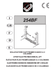
1
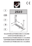
SPRINT JACK
Costruttore WERTHER INTERNATIONAL S.p.A
Manufacturer 42100 Cadè (RE) - Italy
Constructeur
via F.Brunelleschi, 12
Hersteller
Telefono ++/+522/9431 (r.a.)
Constructor Fax ++/+522/941997
Fabrikant
E-Mail [email protected]
Matricola N° - Serial N° - N° de série
Matrikelnummer - Matrícula n°
Anno di costruzione - Year of manufacture
Année de fabrication - Baujahr - Año de fabricación
Rev. 3...............................................21/12/2007
Centro di assistenza autorizzato
Centre d’assistance autorisé
Authorized Service Centre
Kundendiencenter
Centro de Asistencia Autorisado
Geautoriseerde dealer
Fig.1
0
1
2
Fig.2
Fig.3
Fig.4
Fig.5
1
Fig.6
Finecorsa salita/
Lift Limit/
Fin-de-course de montée
Fig.7
Finecorsa discesa/
Descent Limit/
Fin-de-course de descente
NO
Fig.8
Fig.9
2
CAP.2 SPECIFICHE TECNICHE - CHAPTER 2 SPECIFICATIONS -CHAP.2 CARACTERISTIQUES TECHNIQUES
3
Portata
Capacity
Portée
1000 Kg.
Peso massimo autovettura
Maximum car weight
Poids maximum du véhicule
2000 Kg.
Altezza massima di
sollevamento
Max. lifting height
Hauteur maximum de levage
850 mm.
Tempo di salita / discesa
Lifting / Descent time
Temps de montée / descente
35 sec
Alimentazione monofase
Single phase power supply
Alimentation monophasée
230/50
Potenza motore kw
Electric motor power
Puissance du moteur en kW
Peso macchina
Weight
Poids de l’appareil
Comando elettrico con
commutatore
Electric control with switch
Commande électrique avec commutateur
Lifting system by a worm:
screw
Système de levage :
nut
Écrou
safety nut
Écrou de sécurité
Dimensioni ingombro macchina
Overall dimensions
Dimensions d’encombrement de l’appareil
805 x 660 x 1360 [mm]
32,6 x 30,3 x 53,5 [inch]
Dimensioni ingombro imballo
Overall dimensions pack
830 x 770 x 1480 [mm]
32,5 x 30,3 x 58,2 [inch]
Ambiente di lavoro: locale chiuso
Working enviroment: not suitable
for outside use
Temperatura di lavoro
Working temperature range
Dimensions d’encombrement de l’emballage
Milieu de travail requis : local protégé
des intempéries
Températures ambiantes de travail autorisées
Accessorio: presa scocca
Optional: holding device for sill
Accessoire : dispositif de prise pour coque
SI - YES - OUI
Sistema di sollevamento:
a vite
chiocciola
chiocciola di sicurezza
0,73 kW
80 Kg.
Vis
-10°C / +50 °C
4
SCHEMA ELETTRICO MONOFASE
5
SINGLE-PHASE WIRING DIAGRAM
SCHÉMA ÉLECTRIQUE MONOPHASÉ
SIGLA
REF/
SIGLE
DESCRIZIONE
DESCRIPTION
DESCRIPTION
COD.
ART.
FU
PORTA FUSIBILE
(NON FORNITO)
FUSE CARRIER
(NOT SUPPLIED)
PORTE-FUSIBLE
(NON FOURNI)
SA1
COMMUTATORE
SWITCH
COMMUTATEUR
R1415
WIP0161173S001
BOX
BOX COMMUTATORE
SWITCH BOX
BOITIER DU COMMUTATEUR
R1416
WIBF1/2NG0
MI
MOTORE ELETTRICO
ELECTRICAL MOTOR
MOTEUR ELECTRIQUE
R1430
1CV 230V 1Ph
FR
TERMICO MONOFASE
THERMAL
THERMIQUE
R1440
WIFRMF4A
2X10A RIT.
6
IMBALLAGGIO, TRASPORTO E STOCCAGGIO.
LE OPERAZIONI DI IMBALLAGGIO, SOLLEVAMENTO, MOVIMENTAZIONE, TRASPORTO E
DISIMBALLO DEVONO ESSERE AFFIDATE ESCLUSIVAMENTE A PERSONALE CHE SIA
ESPERTO IN TALI OPERAZIONI E CHE CONOSCA BENE IL SOLLEVATORE ED IL PRESENTE
MANUALE
IMBALLAGGIO
Il sollevatore viene spedito completamente montato.
Il sollevatore viene inviato in un cartone appoggiato su di un pallet.
SOLLEVAMENTO E MOVIMENTAZIONE
Le scatole possono essere sollevate e spostate con carrelli elevatori.
STOCCAGGIO
Gli imballi devono sempre essere conservati in luoghi coperti e protetti a temperature comprese fra -10°C
e +40°C. e non devono essere esposti ai raggi diretti del sole.
IMPILAMENTO DEI PACCHI.
Il tipo di imballo previsto prevede la possibilità di impilare in magazzino fino ad 2 cartoni uno sull’altro, purchè vengano correttamente disposte ed assicurati contro la caduta.
Nei cassoni dei camion o nei containers si possono impilare fino a 2 cartoni, purchè vengano reggiati
bene ed assicurati contro la caduta.
APERTURA DEGLI IMBALLI
All’arrivo verificare che la macchina non abbia subito danni durante il trasporto.
I cartoni devono essere aperti adottando tutte le precauzioni per evitare danni alla macchina.
ELIMINAZIONE DELL’IMBALLO.
Il legno ed il cartone possono essere riutilizzato o riciclato.
7
INTRODUZIONE
I ATTENZIONE
Questo manuale è stato scritto per il personale di officina addetto all’uso dello
SprintJack (operatore) e per il tecnico addetto alla manutenzione ordinaria (manutentore) pertanto, prima
di effettuare qualsiasi operazione sul sollevatore e/o sul suo imballaggio, occorre leggere attentamente
tutto il manuale.
CONSERVAZIONE DEL MANUALE
Il manuale è parte integrante dello SprintJack e deve sempre accompagnarlo, anche in caso di vendita.
Lo SprintJack è stato progettato e costruito rispettando quanto segue:
LEGGI
Direttive europee: 73/23 CEE - 89/336 CEE e 98/37/CE
NORME TECNICHE
Norne europee : EN 291 /1992, EN 292 / 1992
IMPIANTO ELETTRICO
Norne europee : UNI EN 60204
l sollevamento, il trasporto, il disimballo, il montaggio, l’installazione e la messa in servizio, la taratura e le registrazioni iniziali, la manutenzione STRAORDINARIA, la riparazione, la revisione,
lo spostamento e lo smantellamento del sollevatore devono essere eseguiti dai tecnici specializzati dei RIVENDITORI AUTORIZZATI o dei CENTRI ASSISTENZA AUTORIZZATI dal Costruttore (vedere centro assistenza autorizzato indicato nel frontespizio):
Il costruttore non risponde di alcun danno a persone, veicoli od oggetti causati dagli interventi
sopracitati se effettuati da personale non autorizzato o da un uso improprio o non consentito del
sollevatore
Nel testo del manuale troverete spesso le diciture “operatore” e “manutentore” il cui significato
è il seguente:
OPERATORE: persona addetta all’uso del sollevatore.
MANUTENTORE: persona addetta alla manutenzione ordinaria del sollevatore.
8
CAP.1. DESCRIZIONE DELLA MACCHINA
Lo Sprintjack è un sollevatore mobile costruito per il sollevamento e stazionamento laterale in
quota di autoveicoli con presa su ruota.
Lo Sprintjack è composto, principalmente da :
· Un Basamento costruito in tubi di acciaio saldati.
· 1 colonna in lamiera di acciaio piegata saldata alla basamento.
· un carrello in lamiera di acciaio saldata, collegato nella parte inferiore, ai bracci sollevamento.
Al centro, il carrello è collegato alla madrevite che, tramite il movimento della vite, ne permette il
sollevamento
Nella parte laterale esso è collegato, mediante perni, ai pattini di scorrimento che lo mantengono
in guida .
GRUPPO DI TRASMISSIONE
E’ composto da una vite elicoidale in acciaio speciale sospese nella parte superiore della colonna mediante un cuscinetto.
La vite della colonna motrice è azionata da un dispositivo composto da un motore elettrico, pulegge e cinghia trapezoidale.
QUADRO DI COMANDO
Sul pannello del quadro elettrico di comando è installato il pulsante di stop/ salita/discesa
SICUREZZE
Una sicurezza meccanica ( chiocciola di sicurezza ) è posta sotto alla chiocciola portante; questa interviene in caso di rottura di quella portante.
PESI MASSIMI DEI VEICOLI DA SOLLEVARE
IATTENZIONE:
IIL PESO MASSIMO DELLA VETTURA DA SOLLEVARE E' DI 2000 KG
IIL DIAMETRO MINIMO DELLA RUOTA DA SOLLEVARE E' DI 500 mm
ILE DIMENSIONI SI RIFERISCONO AL DIAMETRO COMPLESSIVO
DELLA RUOTA CON COPERTONE MONTATO GONFIO.
INON SI DEVE SOLLEVARE IL VEICOLO CON RUOTA SGONFIA O SU
CERCHIONE.
IQUANDO SI USA IL GANCIO O IL PIANO QUESTI DEVONO ESSERE
POSIZIONATI SOLO NEL PUNTO INDICATO DAL COSTRUTTORE.
9
CAP.2 SICUREZZA
É estremamente importante leggere questo capitolo attentamente ed in ogni sua parte poichè
contiene importanti informazioni sui rischi che operatore e manutentore possono correre in caso
di un uso errato dello SprintJack.
I ATTENZIONE:
Lo Sprint jack è un sollevatore mobile costruito per il sollevamento e stazionamento laterale in
quota di autoveicoli con presa su ruota.
Si tratta quindi di un CRIC per sollevare lateralmente le vetture ( vedere fig. 1,3,4,5 )
Il costruttore non risponde di alcun danno a persone, veicoli od oggetti causati dall’uso improprio o non consentito dello Spring Jack .
É estremamente importante che in fase di salita o discesa l’operatore agisca soltanto dalla postazione di comando dietro la colonna del cric
Il sistema a forche è stato progettato per uso presa ruote.
ATTENZIONE ! E’ VIETATO :
·PRENDERE LA MACCHINA CON LE FORCHE IN POSIZIONE DIVERSA DELLE RUOTE (
VEDERE FIG 8 ) .
·SOLLEVARE COMPLETAMENTE IL VEICOLO SIA CON DUE Sprint Jack SIA CON UNO
Sprint Jack ED ALTRE ATTREZZATURE.
·SOLLEVARE LE PERSONE .
·SALIRE SUL VEICOLO E/O METTERLO IN MOTO CON IL VEICOLO SOLLEVATO.
ATTENZIONE!
·IL LAVORO DELL’OPERATORE SOTTO LA VETTURA SOLLEVATA NON È CONSENTITO A
MENO CHE NON SIANO PRESENTI MEZZI SUPPLEMENTARI DI FISSAGGIO DEL CARICO
STESSO QUALI COLONNETTE PER VETTURE .
·L’APPARECCHIATURA DI SOLLEVAMENTO DEVE ESSERE USATA SOLO DA
PERSONALE ADDESTRATO.
·TUTTI I COMPONENTI DEVONO ESSERE TENUTI IN CONDIZIONE DI BUON
FUNZIONAMENTO.
·L’APPARECCHIATURA DEVE ESSERE USATA IN UN’AREA DI LAVORO IDONEA (
PAVIMENTO PORTANTE E NON INCLINATO , IDONEA ILLUMINAZIONE ).
·PER UN CORRETTO FUNZIONAMENTO VERIFICARE PERIODICAMENTE ( MAX OGNI 3
MESI ) L’USURA DELLA CHIOCCIOLA PORTANTE ( FIG. 8 )
·IN CASO DI ROTTURE O NON CORRETTO FUNZIONAMENTO INTERPELLARE IL
SERVIZIO ASSISTENZA DEL COSTRUTTORE / DISTRIBUTORE .
ATTENZIONE !
·RISCHIO DI CADUTA DEL VEICOLO IN CASO DI UN POSIZIONAMENTO NON CORRETTO
DELLA FORCA O CON DIMENSIONI E PESI DEL VEICOLO NON COMPATIBILI CON IL
CRIC.
·RISCHIO DI SCHIACCIAMENTO DEL PERSONALE IN FASE DI DISCESA DEL VEICOLO :
DURANTE LA FASE DI DISCESA IL PERSONALE NON DEVE SOSTARE NELLE ZONE
INTERESSATE DALLE TRAETTORIE DI DISCESA E L’OPERATORE DEVE MANOVRARE
SOLO DOPO ESSERSI ACCERTATO CHE NESSUNA PERSONA SIA IN POSIZIONE
PERICOLOSA.
10
IL MANCATO RISPETTO DI QUESTE NORME PUO’ RECARE GRAVI DANNI ALLE
PERSONE, AL CRIC ED AI VEICOLI SOLLEVATI.
PRECAUZIONI GENERALI
L’operatore ed il manutentore sono tenuti al rispetto delle prescrizioni contenute in leggi e norme antinfortunistiche vigenti nel paese in cui è installato il cric.
Devono inoltre:
- operare sempre dalle postazioni di lavoro previste ed indicate nel manuale;
- non rimuovere nè disattivare i carter e le protezioni meccaniche, elettriche, o di altra natura;
- prestare attenzione agli avvisi di sicurezza riportati nelle targhette applicate sulla macchina e nel manuale.
Nel testo del manuale gli avvisi di sicurezza saranno evidenziati nelle forme seguenti:
PERICOLO: Indica un pericolo imminente che può causare danno alle persone (gravi lesioni o anche la morte).
ATTENZIONE: Indica situazioni e/o comportamenti rischiosi che possono causare danni
alle persone (lesioni più o meno gravi e/o anche la morte).
CAUTELA: Indica situazioni e/o comportamenti rischiosi che possono causare danni di minore gravità
alle persone e/o danni allo SprintJack, al veicolo o ad altre cose.
RISCHIO DI FOLGORAZIONE: è un particolare avviso di sicurezza che viene riportato sul sollevatore,
tramite targhetta, in alcuni punti dove è particolarmente elevato il rischio di forti scosse elettriche
11
CAP.3 FUNZIONAMENTO ED USO
I comandi del sollevatore sono i seguenti:
QUADRO COMANDI FIG.2
POSIZIONE 0:
Lo SprintJack non è in tensione; è possibile l’accesso all’interno del quadro.
POSIZIONE 1 SALITA
Tipo “uomo presente“, funziona sotto tensione; se premuto, aziona il motore elettrico ed i meccanismi che attuano il sollevamento del carrello .
POSIZIONE 2 DISCESA
Tipo “uomo presente“, funziona sotto tensione; se premuto, azione il motore elettrico ed i meccanismi che
attuano la discesa del carrello .
SEQUENZA DI FUNZIONAMENTO
Posizionare la forca dello SprintJack posta nella parte inferiore tra la ruota.
SOLLEVAMENTO
Ruotare l’interrutore in posizione 1 salita fino al raggiungimento dell’altezza desiderata.
STAZIONAMENTO
Una volta raggiunta l’altezza desiderata rilasciare l’interrutore che si posizionerà su 0.
DISCESA
Verificare che sotto al sollevatore non vi siano ostacoli, quindi ruotare l’interrutore in posizione 2
discesa che porta il veicolo a terra o all’altezza voluta.
IL'arresto della salita e della discesa del carrello è regolato dalle camme fig.6-7
IATTENZIONE:
INON SOLLEVARE MAI IL VEICOLO COME IN FIGURA 8
ILO SprintJack E' IDONEO A SOLLEVARE LATERALMENTE LA
VETTURA
IE' VIETATO SOLLEVARE COMPLETAMENTE IL VEICOLO CON DUE
SprintJack OPPURE CON UNO SprintJack ED ALTRE
ATTREZZATURE
12
Cap.4 MANUTENZIONE
MANUTENZIONE PERIODICA
Per mantenere lo SprintJack in piena efficienza, è necessario attenersi alle tempistiche di manutenzione indicate.
IL MANCATO RISPETTO DI QUANTO SOPRA ESONERA IL COSTRUTTORE DA
QUALUNQUE RE SPONSABILITA’ AGLI EFFETTI DELLA GARANZIA.
I NOTA:
Le periodicità indicate si riferiscono a condizioni di funzionamento normali; in condizioni particolarmente severe si richiedono periodicità diverse.
TUTTE LE OPERAZIONI DI MANUTENZIONE DEVONO ESSERE EFFETTUATE CON
SOLLEVATORE FERMO
DOPO 1 SETTIMANA
dall’installazione verificare:
· La tensione delle cinghie di trasmissione motore.
· Verificare che sulla vite sia presente un velo di grasso, se necessario lubrificare.
( minimo ogni settimana)
OGNI 3 MESI...
· Verificare tensione delle cinghie di trasmissione del motore.
· Ingrassare i cuscinetti delle viti posti alle sommità delle colonne mediante ingrassatore.
· Verificare lo stato di usura delle chiocciole portanti attraverso il foro di controllo posto sul carrello fig.9
APPENDICE A INFORMAZIONI
DEMOLIZIONE DELLA MACCHINA
DURANTE LA DEMOLIZIONE DELLA MACCHINA DEVONO ESSERE OSSERVATE TUTTE LE
PRECAUZIONI DI SICUREZZA ILLUSTRATE AL CAPITOLO 3 E VALIDE PER IL MONTAGGIO.
La demolizione della macchina deve essere effettuata da tecnici autorizzati, come per il montaggio.
Le parti metalliche possono essere rottamate come rottami ferrosi.
In ogni caso tutti i materiali derivati dalla demolizione devono essere smaltiti in accordo alla normativa vigente del paese in cui il ponte è installato.
Si ricorda inoltre che, ai fini fiscali, occorre documentare l’avvenuta demolizione producendo denunce e
documenti secondo la legislazione vigente nel paese in cui il ponte è installato al momento della demolizione stessa.
APPENDICE B PARTI DI RICAMBIO
RICAMBI
la sostituzione dei pezzi e gli interventi di riparazione richiedono il rispetto di TUTTE LE
PRECAUZIONI DI SICUREZZA indicate al capitolo 5 “MANUTENZIONE” e al capitolo 3
SICUREZZA”.
PROCEDURA PER L’ORDINAZIONE DEI PEZZI DI RICAMBIO
Per ordinare pezzi di ricambio occorre:
· indicare il numero di matricola del sollevatore e l’anno di costruzione;
· indicare la quantità richiesta.
· Indicare il riferimento della parte richiesta che appare nella colonna "CODICE" della nomenclatura qui di seguito
La richiesta deve essere fatta al rivenditore autorizzato indicato nel frontespizio.
13
PACKING, TRANSPORT AND STORAGE
ALL PACKING, LIFTING, HANDLING, TRANSPORT AND UNPACKING OPERATIONS ARE
TO BE PERFORMED EXCLUSIVELY BY EXPERT PERSONNEL WITH KNOWLEDGE OF
THE LIFT AND THE CONTENTS OF THIS MANUAL
PACKING
The lift is shipped completely assembled.
The jack is shipped in a cardboard box on a pallet.
LIFTING AND HANDLING
The boxes can be lifted and moved with lift trucks
STORAGE
Packed machinery must always be kept in a covered, protected place, at a temperature between -10 °C e + 40°C, and must not be exposed to direct sunlight.
CRATE STACKING.
Thanks to the type of packing, up to 2 boxes can be stacked on each other provided they are
placed properly and cannot fall.
Up to 2 boxes can be stacked on each other in lorries or containers provided they are firmly
strapped and cannot fall..
OPENING THE CRATES
Upon arrival check that the machine has not been damaged during transport.
The boxes must be opened taking all the necessary precautions to avoid damaging the machine.
DISPOSAL OF CRATES
The wood and cardboard can be reutilised or recycled
14
INTRODUCTION
I WARNING
This manual has been prepared for workshop personnel expert in the use of the SprintJack (operator) and technicians responsible for routine maintenance (maintenance fitter); read the manual before carrying out any operation with the lift and/or the packing.
CONSERVING THE MANUAL
The manual is an integral part of the
SprintJack, which it should always accompany , even if the unit is sold.
The SprintJack rack has been designed and built in compliance with the following
LAWS
European directives: 73/23 CEE - 89/336 CEE and 98/37/CE
TECHNICAL STANDARDS
European standards: EN 291 /1992, EN 292 / 1992
ELECTRIC PLANT
European standards: Uni En 60204
The lifting, transport, unpacking, assembly, installation, starting up, initial adjustment and testing,
EXTRAORDINARY maintenance, repair, overhauls, transport and dismantling of the lift must be
performed by specialised personnel from the LICENSED DEALER or an SERVICE CENTRE
authorised by the manufacturer (see authorised dealer on front cover).
The manufacturer declines all responsibility for injury to persons or damage to vehicles or objects
when any of the above mentioned operations has been performed by unauthorised personnel or
when the rack has been subject to improper use.
The words “operator” and “maintenance fitter” used in this manual are construed as follows:
OPERATOR: person authorised to use the lift
MAINTENANCE FITTER: person authorised for routine maintenance of the lift.
15
CHAPTER 1.DESCRIPTION OF THE MACHINE
Sprintjack is a mobile lift designed to lift and hold vehicles laterally, gripping the wheel.
The SprintJack mainly comprises:
Base made of welded steel tubes.
· 1 bent steel plate post welded to the baseplate a welded sheet steel carriage connected to the lif-
ting arms at the bottom.
· In the centre the carriage is connected to the lead nut which provides the lifting motion via the
movement of the screw.
The carriage is laterally joined by pins to sliding shoes which keep it on the slide ways
TRANSMISSION UNIT
The unit comprises one special-steel helical screw suspended in the upper part of the post by a
bearing.
The screw of the drive post is operated by a device consisting of an electric motor , pulleys and a
V-belt.
CONTROL PANEL
The STOP/UP/DOWN push button is installed on the electrical control panel
SAFETY DEVICES
A mechanical safety device (safety nut) is under the load bearing nut; this intervenes if the load bearing nut breaks.
MAXIMUM WEIGHT OF THE VEHICLE TO BE LIFT
I WARNING:
ITHE MAXIMUM WEIGHT OF THE VEHICLE TO LIFT IS 2000 Kg.
ITHE MINIMUM DIAMETER OF THE WHEEL TO LIFT IS 500 mm
ITHIS DIMENSION REFERS TO THE OVERALL DIAMETER OF THE
TYRE ACTUALLY FITTED ON THE WHEEL.
IYOU MUST NOT LIFT THE VEHICLE BY THE WHEEL USING THE
FORK UNLESS TYRE IS CORRECTLY INFLATED.
IWHEN USING SILL PAD / HOOK IT SHOULD ONLY BE POSITIONED
AT THE RECOMMENDED LIFTING POINTS FOR THAT VEHICLE
16
CHAPTER 2 SAFETY
It is vital to read this chapter of the manual carefully and from beginning to end as it contains important information regarding the risks that the operator or maintenance fitter may be exposed to in the
eventuality that the SprintJack is used incorrectly.
I WARNING:
The Sprint Jack is a mobile hoist designed to lift cars and keep them in raised position taking the vehicle laterally from its wheel.
- JACK for lifting vehicles.
The manufacturer disclaims all liability for injury to persons or damage to vehicles and other property
caused by the incorrect and unauthorised use of the lift.
During lift and descent movements, the operator must remain in the command station.
It is a JACK for lifting cars laterally (see Figs. 1, 3, 4, 5)
The manufacturer is not liable for any injuries to people or damage to vehicles or objects caused by
an improper or forbidden use of the Spring Jack.
It is extremely important that the operator, during the up and down phases, works from his work
station, behind the jack column.
The fork system is designed for gripping the wheels.
ATTENTION! IT IS FORBIDDEN TO:
· LIFT THE CAR WITH THE FORKS OTHER THAN BY THE WHEELS (SEE FIG. 8)
· LIFT THE VEHICLE COMPLETELY EITHER WITH TWO Sprint Jacks OR WITH ONE Sprint Jack
AND OTHER EQUIPMENT.
· LIFT PEOPLE.
· GET INTO THE VEHICHLE AND/OR START IT WHILE IT IS RAISED.
ATTENTION!
· IT IS FORBIDDEN FOR THE OPERATOR TO WORK UNDER THE RAISED VEHICLE UNLESS ADDITIONAL
MEANS ARE USED TO SECURE THE LOAD, SUCH AS AXLE STANDS FOR CARS.
· THE LIFTING EQUIPMENT MUST ONLY BE USED BY TRAINED PERSONNEL.
· ALL COMPONENTS MUST BE KEPT IN GOOD WORKING CONDITION.
· THE EQUIPMENT MUST BE USED IN A SUITABLE WORKING AREA (A COMPLETELY LEVEL, BEARING FLOOR,
SUITABLE LIGHTING).
· TO ENSURE CORRECT OPERATION, CHECK WEAR OF THE LOAD BEARING NUT (FIG. 8) REGULARLY (MAX.
EVERY 3 MONTHS).
· IN THE CASE OF BREAKS OR INCORRECT OPERATION, CONTACT THE MANUFACTURER’S or DISTRIBUTOR’S ASSISTANCE SERVICE.
ATTENTION!
· RISK OF THE VEHICLE FALLING IF THE FORK IS NOT POSITIONED CORRECTLY OR IF THE SIZE AND
WEIGHT OF THE VEHICLE ARE INCOMPATIBLE WITH THE JACK.
· CRUSHING HAZARD WHEN THE VEHICLE IS BEING LOWERED: DURING THE LOWERING PHASE PEOPLE
MUST NOT STAY IN THE AREA UNDER THE VEHICLE AS IT IS BEING LOWERED AND THE OPERATOR MUST
ONLY LOWER THE VEHICLE ONCE HE HAS MADE CERTAIN THERE IS NO ONE IN A DANGEROUS POSITION.
17
FAILURE TO COMPLY WITH THESE REGULATIONS CAN CAUSE SERIOUS INJURY TO PERSONS, AND IRREPERABLE DAMAGE TO THE JACKS AND THE VEHICLE BEING LIFTED.
GENERAL PRECAUTIONS
The operator and the maintenance fitter are required to observe the prescriptions of accident prevention legislation in force in the country of installation of the jacks.
Furthermore, the operator and maintenance fitter must:
- Always work in the scheduled working area as shown in the manual.
- never remove or deactivate the guards and mechanical, electrical, or other types of safety devices;
- read the safety notices affixed to the machine and the safety information in this manual.
In the manual all safety notices are shown as follows:
DANGER: Indicates imminent danger that can result in serious injury or death..
WARNING: Indicates situations and/or types of manoeuvres that are unsafe and can cause injuries
of various degrees or death.
CAUTION: Indicates situations and/or types of manoeuvres that are unsafe and can cause minor injury to persons and/or damage the SprintJack, the vehicle or other property.
RISK OF ELECTRIC SHOCK: specific safety notice affixed to the lift in areas where the risk of electric shock is particularly high.
18
CHAPTER 3 OPERATION AND USE
The lift commands include:
CONTROL BOX FIG.2
POSITION 0: The SprintJack is not receiving electrical power: access to panel is possible.
POSITION 1 LIFT BUTTON
“Hands-on” type, works under tension: when pressed it starts the electric motor and the mechanisms that lift the carriage
POSITION 2 DESCEND BUTTON
“Hands-on” type, works under tension: when pressed it starts the electric motor and the mechanisms
that lower the carriage
OPERATING SEQUENCE
Place the SprintJack fork at the bottom of the wheel.
LIFTING
Turn the switch to position 1, it lifts up to the height wanted.
PARKING
Release lift button once the desired height has been reached (it goes to 0).
DESCENT
After ensuring that no obstacles are under the lift, turn the switch round to the descent position 2
which lowers the vehicle to the desired height or to the ground.
ICams (Fig6-7) see to stopping carriage lifting and lowering
IWARNING!
NEVER LIFT A VEHICLE AS SHOWN IN THE FIGURE 8
ITHE SprintJack IS SUITABLE FOR LIFTING VEHICLES LATERALLY
19
CHAPTER 4
MAINTENANCE
PERIODICAL MAINTENANCE
To maintain the SprintJack in good working order, the following indications must be observed.
FAILURE TO RESPECT THESE RECOMMENDATIONS WILL EXEMPT THE MANUFACTURER
FROM ALL RESPONSIBILITIES ENTAILED IN THE GUARANTEE.
I N.B.:
The frequencies shown refer to standard working conditions; different frequencies will be necessary
if conditions are particularly tough.
ALL THE MAINTENANCE OPERATIONS MUST BE DONE WITH THE LIFT STOPPED
SEVEN DAYS
after installation, check:
· The tension of the motor drive belts.
· Check there is grease on the screw, lubricate if necessary
(every week minimum).
EVERY THREE MONTHS
· Check tension of motor drive belts.
· Grease the lead screw bearings at the top of the posts using grease nipples
· Check wear of the lifting nuts through the inspection hole on the carriage, Fig. 9
APPENDIX A
INFORMATIONS
SCRAPPING THE MACHINE
WHEN SCRAPPING THE MACHINE OBSERVE ALL PRECAUTIONS ILLUSTRATED IN
CHAPTER 3, ADOPTED ALSO DU-RING MACHINE ASSEMBLY.
The machine can only be scrapped by authorised technicians, as in the case of assembly.
Metal parts of the lift can be disposed of as scrap ferrous material.
In all cases when the machine is scrapped all materials must be disposed of in conformity with the
laws in force in the country of installation of the machine.
Note also, that for tax purposes the effective scrapping of the machine must be documented with reports and forms in compliance with the laws in force in the country of installation.
APPENDIX B
SPARE PARTS
SPARES
Parts substitution and repairs need the observance of all the SAFETY PRECAUTIONS
shown in the chapter 5 “MAINTENANCE” and in the chapter 3 “SAFETY”.
SPARE ORDERING PROCEDURE
To order the spare parts it is necessary to:
· indicate the lift serial number and the year of manufacturing.
· Indicate the quantity requested
· To indicate the reference of the desired part appearing in the column "CODES" nomenclature
hereafter
The order must be placed with the authorized distributor shown in the first page.
20
CONDITIONNEMENT, TRANSPORT ET STOCKAGE
LES OPERATIONS DE CONDITIONNEMENT, DE MANUTENTION, DE TRANSPORT ET DE
STOCKAGE DEVRONT ETRE CONFIEES EXCLUSIVEMENT A UN PERSONNEL
EXPERIMENTE DANS CE TYPE D’OPERATION ET CONNAISSANT BIEN L’ELEVATEUR ET
LE PRESENT MANUEL D’INSTRUCTIONS..
CONDITIONNEMENT
L’élévateur est expédié complètement assemblé..
L’appareil est livré dans un emballage carton fixé sur une palette.
MANUTENTION
Les colis peuvent être soulevées et déplacées à l’aide de chariots élévateurs
STOCKAGE
Les appareils emballés devront toujours être stockés dans des endroits couverts et protégés, à des
températures comprises entre -10°C et +40°C et à l’abri du rayonnement direct du soleil.
GERBAGE DES COLIS
Le type d’emballage adopté permet d’empiler en magasin jusqu’à 2 colis l’un sur l’autre pourvu qu’ils
soient correctement placés et assurés contre tout risque de chute.
Dans les camions ou les conteneurs, il est possible d’empiler jusqu’à 2 colis pourvu qu’ils soient sanglés et protégés contre tout risque de chute.
OUVERTURE DES COLIS
A la réception, s’assurer que le matériel n’ait subit aucune avarie durant le transport et que tous les
éléments indiqués sur le bordereau de colisage soient présents.
Les colis devront être ouvertes en prenant toutes précautions afin d’éviter d’endommager leur contenu (éviter de faire tomber des éléments de l’élévateur en ouvrant la caisse).
ÉLIMINATION DE L’EMBALLAGE
Le bois de le carton peut être réutilisé ou recyclé.
21
INTRODUCTION
I ATTENTION
Ce manuel a été rédigé pour le personnel d’atelier affecté à l’utilisation du Sprint Jack (opérateur) et
pour l’agent affecté à l’entretien courant (agent d’entretien) toutefois, avant d’effectuer quelque opération que ce soit sur l’élévateur et / ou sur son emballage, il est nécessaire de lire attentivement et
entièrement ce manuel d’instructions.
CONSERVATION DU MANUEL
Ce manuel fait intégralement partie de Sprint Jack et doit toujours l’accompagner, même en cas de revente
Le Sprint Jack a été conçu et construit en respectant des dispositions suivantes
LÉGISLATION
Directives européennes: 73/23 CEE - 89/336 CEE et 98/37/CE
NORMES TECHNIQUES
Normes européennes: EN 291/1992, EN 292/1992
ÉQUIPEMENT ÉLECTRIQUE
Normes européennes: UNI EN 60204 .
La manutention, le transport, le déballage, le montage, l’installation et la mise en service, le tarage et
les réglages initiaux, l’entretien EXTRAORDINAIRE, la réparation, la révision, le déplacement ou le
démantèlement de l’élévateur devront être exécutés par les techniciens spécialisés des
REVENDEURS AUTORISÉS ou des CENTRES TECHNIQUES AGRÉÉS par le constructeur
(voir l’adresse indiquée en première page).
Le constructeur dégage toute responsabilité concernant les dommages aux personnes, véhicules et
bien causés par les interventions mentionnées ci-dessus lorsqu’elles sont effectuées par un personnel non autorisé ou par une utilisation inadaptée et non prévue de l’élévateur.
Dans le texte de ce manuel, vous trouverez souvent les mots “opérateur” et “agent d’entretien”
dont la signification est la suivante:
OPÉRATEUR: personne affectée à l’utilisation de l’élévateur
AGENT D’ENTRETIEN: personne affectée à l’entretien courant de l’élévateur.
22
CHAP.1
DESCRIPTION DE L’APPAREIL
Le Sprintjack est un élévateur mobile conçu pour le levage et le maintien latéral en hauteur d’un véhicule, la prise s’effectuant sur une roue.
Le sprint Jack comprend principalement:
· une base réalisée en tubes en acier, soudés.
· 1 colonne en tôle d’acier, pliée et soudée sur la base.
· Un chariot en acier soudé à la partie inférieure duquel sont reliés les bras de levage.
Le chariot est relié en partie centrale à l’écrou porteur qui entraîné par la rotation de la vis
produit le mouvement de levage.
Il est relié latéralement par des axes aux patins de guidage qui glissent à l’intérieur de la colonne.
GROUPE DE TRANSMISSION
Il se compose d’une vis à filet hélicoïdal en acier spécial suspendue à la partie supérieure de la colonne par une butée à bille.
La vis porteuse est actionnée par un système comprenant un moteur électrique, deux poulies et une
courroie trapézoïdale.
TABLEAU DE COMMANDE
Le bouton poussoir de « Stop / Montée / Descente » est situé sur le panneau du tableau
électrique de commande.
DISPOSITIFS DE SÉCURITÉ
Une sécurité mécanique (vis sans fin de sécurité) est située sous la vis sans fin portante
; cette sécurité intervient en cas de cassure de la vis portante.
POIDS MAXIMAL DES VÉHICULES A SOULEVER Fig.12
I ATTENTION
ILE POIDS MAXIMUM DE LA VOITURE À LEVER LATERALEMENT EST DE
2000 KG
ILE DIAMETRE MINIMUM DE LA ROUE À LEVER EST DE 500 mm
ILes dimensions se réfèrent au diamètre de la roue avec le pneu gonflé
IOn ne doit pas soulever le véhicule avec la roue dégonflé ou sur jantes
IQuand on utilise la prise sous coque l’option doit être fixé seulement sur le
point indiqué par le constructeur (pag. 10 de la notice)
23
CHAP.2
SÉCURITÉ
Il est extrêmement important de lire attentivement et entièrement ce chapitre qui contient des informations importantes sur les risques encourus par l’opérateur et l’agent d’entretien en cas de mauvaise utilisation du Sprint Jack.
IATTENTION
Le Sprint Jack est un cric mobile construit pour le soulèvement et stationnement latéral dans
cote d'autoveicoli avec prise sur roue.
Il s’agit donc d’un CRIC destiné au levage latéral des véhicules (voir les fig. 1,3,4,5)
Le fabricant ne répondra en aucun cas des dommages aux personnes, véhicules, choses, etc., causés par une utilisation abusive ou non autorisée du Spring Jack.
Il est extrêmement important que pendant la phase de montée ou de descente l’opérateur agisse
toujours uniquement à partir du poste de commande situé derrière la colonne du cric.
Le système à fourches a été conçu uniquement pour réaliser la prise au niveau des roues.
ATTENTION ! IL EST STRICTEMENT INTERDIT :
· DE SAISIR UN VÉHICULE AVEC LES FOURCHES DANS UNE POSITION AUTRE QU’AU NIVEAU
DES ROUES ( VOIR LA FIG 8 ).
· DE SOULEVER COMPLÈTEMENT LE VÉHICULE AVEC DEUX Sprint Jack OU BIEN AVEC UN
Sprint Jack ET D’AUTRES ÉQUIPEMENTS.
· DE SOULEVER UNE OU PLUSIEURS PERSONNES.
· DE MONTER SUR LE VÉHICULE ET/OU DE LE METTRE EN MARCHE LORSQU’IL EST
SOULEVÉ.
ATTENTION !
· LE TRAVAIL DE L’OPÉRATEUR SOUS LA VOITURE SOULEVÉE EST STRICTEMENT INTERDIT
SAUF SI ON POSITIONNE PRÉALABLEMENT DES MOYENS SUPPLÉMENTAIRES ADÉQUATS DE
SUPPORT ET MAINTIEN DE LA CHARGE, PAR EXEMPLE DE SOLIDES COLONNES DE
SUPPORT POUR VÉHICULES.
· L’APPAREIL DE LEVAGE DOIT ÊTRE UTILISÉE UNIQUEMENT PAR UN PERSONNEL
PROFESSIONNEL CORRECTEMENT FORMÉ.
· TOUS LES COMPOSANTS DOIVENT ÊTRE CONSERVÉS EN PARFAITE CONDITION DE
FONCTIONNEMENT.
· L’APPAREIL DOIT ÊTRE UTILISÉ DANS UNE ZONE DE TRAVAIL ADÉQUATE ( SOL TRÈS
SOLIDE, PARFAITEMENT HORIZONTAL ET BIEN ÉCLAIRÉ ).
· POUR OBTENIR UN BON FONCTIONNEMENT, VÉRIFIER RÉGULIÈREMENT (AU MAXIMUM
TOUS LES 3 MOIS ) L’USURE DE LA VIS SANS FIN PORTANTE ( FIG. 8 ).
· EN CAS DE CASSURE OU DE MAUVAIS FONCTIONNEMENT, CONTACTER IMMÉDIATEMENT
LE SERVICE ASSISTANCE DU FABRICANT / DU DISTRIBUTEUR.
ATTENTION !
· EN CAS DE MAUVAIS POSITIONNEMENT DE LA FOURCHE OU EN PRÉSENCE DE
DIMENSIONS ET/OU POIDS DU VÉHICULE NON COMPATIBLES AVEC LE CRIC IL EXISTE UN
RISQUE DE CHUTE DU VÉHICULE.
· IL EXISTE UN RISQUE D’ÉCRASEMENT DU PERSONNEL LORS DE LA PHASE DE DESCENTE
DU VÉHICULE : PENDANT LA PHASE DE DESCENTE AUCUNE PERSONNE NE DOIT RESTER
DANS LA ZONE INTÉRESSÉE PAR LES TRAJECTOIRES DE DESCENTE ET L’OPÉRATEUR DOIT
MANŒUVRER UNIQUEMENT APRÈS S’ÊTRE ASSURÉ QU’AUCUNE PERSONNE N’OCCUPE
UNE POSITION DANGEREUSE.
24
LE NON RESPECT DE CES CONSIGNES PEUT ENTRAÎNER DE GRAVES DOMMAGES AUX
PERSONNES, A LE CRIC ET AU VÉHICULE SOULEVÉ.
PRÉCAUTIONS GÉNÉRALES
L’opérateur et l’agent d’entretien sont tenus au respect des prescriptions définies par la législation du
travail en vigueur dans le pays où est installé le cric.
Ils doivent en outre,
- opérer toujours depuis les emplacements de travail indiqués dans le manuel;
- ne pas enlever ou neutraliser les carters et les protections mécaniques, électriques ou de toute
autre nature;
- respecter les consignes de sécurités affichées sur l’appareil ou inscrites dans le manuel.
Dans le manuel, les avertissements de sécurité seront mis en évidence sous les formes suivantes:
DANGER: indique un danger imminent qui peut avoir de graves conséquences sur les personnes
(blessures graves voir décès).
ATTENTION: indique des situations ou des comportements à risque qui peuvent avoir des conséquences sur les personnes (blessures plus ou moins graves voir décès).
PRÉCAUTION: indique des situations ou des comportements qui risquent de causer des lésions
mineures aux personnes ou des dommages à l’élévateur, au véhicule soulevé ou à d' autres objets.
RISQUE D’ÉLECTROCUTION: avis de sécurité particulier placé sur l’élévateur même, aux endroits
où le risque d’électrocution est particulièrement élevé.
25
CHAP. 3
FONCTIONNEMENT ET UTILISATION
Les commandes de l’élévateur comprennent:
TABLEAU DE COMMANDE FIG.2
POSITION O:
Le Sprint Jack est hors tension, il est possible d’ouvrir le coffret électrique
POSITION 1: MONTÉE
De type “commande maintenue”,,son action provoque la mise en route du moteur électrique et des
mécanismes qui entraînent la montée des chariots.
POSITION 2: DESCENTE
De type “commande maintenue”, son action provoque la mise en route du moteur élec trique et des
mécanismes qui entraînent la descente des chariots.
SEQUENCE DE FONCTIONNEMENT
Positionner la fourche du SprintJack correctement enfilée sous une roue
MONTÉE
Une fois la hauteur désirée atteinte, relâcher le bouton de montée (il reviendra automatiquement en
position 0).
STATIONNEMENT
Une fois la hauteur désirée atteinte, relâcher le bouton de montée et remettre l’interrupteur général
sur la position 0.
DESCENTE
S’assurer qu’aucun obstacle ne se trouve dans la zone d’action de l’élévateur, tourner le commutateur sur la position 2 et descendre le véhicule jusqu’à la hauteur désirée ou jusqu’au sol.
IL’arrêt de la montée et de la descente du chariot est réalisé grâce à
des cames fig.6-7
IATTENTION NE JAMAIS LEVER LE VEHICULE DE LA MANIÈRE
MONTRÉE SUR LA FIGURE 8
ILE SprintJack EST CONCU POUR EFFECTUER LE LEVAGE LATERAL
DE LA VOITURE
IIL EST STRICTEMENT INTERDIT DE SOULEVER ENTIEREMENT LE
VÉHICULE AVEC DEUX SprintJack OU UN SEUL SprintJack ET
D’AUTRES EQUIPEMENTS.
26
CHAP. 4
ENTRETIEN
ENTRETIEN PÉRIODIQUE
Pour maintenir l’éIévateur en parfaite condition, il est nécessaire de respecter scrupuleusement la périodicité d’entretien .
LE NON RESPECT DE CETTE RECOMMANDATION DÉGAGE LE CONSTRUCTEUR DE TOUTE
RESPONSABILITÉ, EN PARTICULIER VIS À VIS DE LA GARANTIE.
I NOTA:
La périodicité indiquée correspond à un usage normal du pont. En cas d’utilisation intensive, les
opérations d’entretien devront être plus rapprochées.
TOUTES LES OPERATIONS D’ENTRETIEN DOIVENT ETRE EFFECTUEES AVEC
L’ELEVATEUR A L’ARRET ET ISOLE DE SA SOURCE D’ALIMENTATION.
APRÈS LA PREMIERE SEMAINE de fonctionnement, :
· Vérifier la tension de la courroie d’entraînement.
· Vérifier la présence permanente d’un film de graisse sur la vis ; si nécessaire lubrifier.(au moins une fois par
semaine)
TOUS LES 3 MOIS
· Vérifier la tension de la courroie d’entraînement.
· Graisser le roulement et la butée à bille de suspension de la vis en sommet de colonne au moyen du graisseur.
· Vérifier l’usure de l’écrou porteur au travers du trou de visite dans le chariot, fig.9.
ANNEXE A
Informations particulières
DESTRUCTION DE L’ÉLÉVATEUR
LES CONSIGNES DE SÉCURITÉ POUR LE MONTAGE, MENTIONNÉES AU PARAGRAPHE 3,
SONT À RESPECTER AUSSI POUR LE DÉMONTAGE ET LA DESTRUCTION DE L’ÉLÉVATEUR.
La destruction de l’élévateur, doit être effectuée, comme le montage, par des techniciens spécialisés.
Les parties métalliques devront être traitées comme ferraille.
De toute façon, les matériaux résultant de la destruction devront être éliminés conformément à la législation en vigueur dans le pays où l’élévateur était installé au jour de sa démolition.
Il est important en outre, pour des raisons fiscales, de déclarer la destruction de l’élévateur conformément
à la réglementation en vigueur dans le pays où l’élévateur était installé au jour de sa démolition.
ANNEXE B PIÈCES DÉTACHÉES
PIÈCES DÉTACHÉES
Le remplacement de pièces et les opérations de réparation nécessitent le respect de TOUTES LES
PRÉCAUTIONS DE SÉCURITÉ indiquées au chapitre 5 “ENTRETIEN” et au chapitre 3
“SÉCURITÉ”.
PROCÉDURE POUR LA COMMANDE DE PIÈCES DÉTACHÉES
Pour toute commande de pièces détachées:
· indiquer le numéro de série de l’élévateur et son année de fabrication;
· indiquer la quantité désirée.
· Indiquer la référence de la pièce souhaitée figurant dans la colonne « CODE » de la nomenclature ci-après
La commande doit être adressée au Centre Technique dont l’adresse figure en première page
27
Part Code
Descrizione
Description
Beschreibung
Description
Denominacion
A0346
RONDELLA P 12 X 24 UNI 6592
WASHER 12 X 24
UNTERLEGSCHEIBE 12 X 24
RONDELLE Ø13X24
ARANDELA 13X24
A0433
DADO AUTOBLOCCANTE M12
ZINCATO
SELF-LOCKING NUT M12
SELBSTSPERRENDEMUTTER M12
ECROU FREIN M12
TUERCA AUTOBLOQUEADORA M12
ZINCADA
A0745
VITE TCEI M6X12 UNI 5931 ZB
HEX. SOCKET HEAD SCREW M6X12
UNI 5931 ZB
VERZINKT ZYLINDERSCHRAUBE MIT
INNENSECHSKANT M6X12
VIS TCEI M6X12 GALVANISÉE
TORNILLO TCEI M6X12 UNI 5931
A1420
VITE TE 6X12 UNI 5739
SCREW 6X12 8.8 UNI 5739
SCHRAUBE 6X12 8.8
VIS TE 6X12 8.8
TORNILLO
B3777
VITE TE M12X45 UNI 5739 ZB
SCREW M12X45 UNI 5739 ZB
SCHRAUBE M12X45 UNI 5739 ZB
VIS M12X45 UNI 5739 ZB
TORNILLO M12X45 UNI 5739 ZB
B5008
RONDELLA P 21X37X3 UNI 6592
WASHER Ø21X37X3 UNI 6592
UNTERLEGSCHEIBE Ø21X37X3 UNI
6592
RONDELLE PLATE 21X37 UNI 6592
ARANDELA 21X37 UNI 6592
C0099
VITE TE 6X20 8.8 UNI 5739
SCREW M6X20 - 8.8
SCHRAUBE M6X20 8.8
VIS TH M6 X 20 UNI 5739
TORNILLO TE M6X20 UNI 5739
C0617
RONDELLA Ø6,4X12,5 UNI 6592
WASHER Ø6,4X12,5 UNI 6592
SCHEIBE Ø6,4X12,5 UNI 6592
RONDELLE Ø6,4X12,5 UNI 6592
ARANDELA Ø6,4X12,5 UNI6592
C2193
VITE TCCE M5X50 UNI 5931
SCREW TCCE M5X50 UNI 5931
SCRAUBE TCCE M5X50 UNI 5931
VIS TCCE M5X50 UNI 5931
TORNILLO TCCE M5X50 UNI 5931
R0046
DADO MEDIO M12 UNI 5588
NUT M12
MUTTER M12 UNI 5588
ECROU M12 UNI 5588
TUERCA M12 UNI 5588
R1016
VITE TE M12X70 PF UNI5737
SCREW M12X70 PF UNI5737
SCHRAUBE
VIS M12X70 UNI5737
TORNILLO
R1400XX
CARRELLO SJ
CARRIAGE
CHARIOT
CARRO
PATTINO SJ
PAD
GLEITSCHUH
PATIN
PATÍN
R1402
BLOCCHETTO DI FULCRO SJ
BLOCK
BLOCK
BLOC
BLOQUE
R1403
NOTTOLINO DI REGISTRO SJ
PAWL
CAME
PESTILLO
R1404
LEVA AZIONAMENTO ARRESTI SJ
LEVER
R1405
ASTA AZIONAMENTO SJ
MOVING ROD
R1406XX
PIASTRA SUPERIORE COLONNA SJ
POST CAP
R1407
BOCCOLA SJ
BUSH
R1408
VITE PORTANTE SJ
LIFTING SCREW
R1409
CHIOCCIOLA PORTANTE SJ
BEARING NUT
R1410
CHIOCCIOLA SICUREZZA SJ
SAFETY NUT
R1411
PULEGGIA SJ
PULLEY
SCHEIBE
POULIE
POLEA
R1412
PULEGGIA MOTORE SJ
MOTOR PULLEY
MOTORTRAGSCHEIBE
POULIE MOTEUR
POLEA MOTOR
R1413
DISTANZIALE PULEGGIA SJ
SPACER
DISTANZSTUECK
ENTRETOISE
DISTANCIADOR
R1415
COMMUTATORE SJ
RISING-LOWERING SWITCH
WAHLSCHALTER AUF - AB
COMMUTATEUR MONTEE-DESCENTE
CONMUTADOR
R1416
CASSETTA COMMUTATORE SJ
ELECTRIC BOX
KASTEN
COFFRET
CAJA ELÉCTRICA
R1417XX
TELAIO SJ
FRAME
GESTELL
CHASSIS
BASTIDOR
R1418
STAFFA SOLLEVAMENTO SCOCCA
SUPPORT CHASSIS
BÜGEL
SUPPORT
SOPORTE
R1419
FLANGIA DISTANZIALE MOTORE SJ
FLANGE
FLANSCH
BRIDE
BRIDA
R1420XX
CARTER SUPERIORE SJ
UPPER CASING
OBERES GEHÄU
CARTER SUPÉRIEUR
PROTECCION SUPERIOR
R1421
CHIAVETTA 5X5X25 UNI 6604
KEY 5X5X25 UNI 6604
KEIL 5X5X25 UNI 6604
CLAVETTE 5X5X25 UNI 6604
CHAVETA 5X5X25 UNI 6604
R1422
RONDELLA 6,4 DIN 9021
WASHER 6,4 DIN 9021
UNTERLEGSCHEIBE 6,4 DIN 9021
RONDELLE 6,4 DIN 9021
ARANDELA 6,4 DIN 9021
R1401
Sugg
*
HEBEL
BUECHSE
HAUPTSCHNECKE
LEVIER
PALANCA
TIGE D’ACTIONNEMENT
ASTA ACCIONAMIENTO
CAPOT COLONNE
PLACA SUPERIOR
DOUILLE
CASQUILLO
VIS PORTEUR
TORNILLO PORTANTE
ÉCROU PORTEUR
TORNILLO PATRÓN PORTANTE
ECROU SECURITE
TORNILLO PATRÓN DE SEGURIDAD
SECHSSCHRAUBE MIT
INNENSECHSKANT M6X35 UNI 5933
ZB
VIS STHC TSCE90ØM6X35 UNI 5933
ZB
TORNILLO TSCE90ØM6X35 UNI 5933
ZB
R1423
VITE TSCE90ØM6X35 UNI 5933 ZB
SCREW TSCE90ØM6X35 UNI 5933 ZB
R1424
VITE M4X8 EN ISO 7045
SCREW M4X8 EN ISO 7045
SENKSCHRAUBE M4X8 EN ISO 7045
VIS M4X8 EN ISO 7045
TORNILLO M4X8 EN ISO 7045
R1425
RUOTA NB GF 80
WHEEL NB GF 80
RAD NB GF 80
ROUE NB GF 80
RUEDA NB GF 80
R1426
RUOTA NB SR 100
WHEEL NB SR 100
RAD NB SR 100
ROUE NB SR 100
RUEDA NB SR 100
R1427
CINGHIA A31 TRAPEZOIDALE
BELT A31
RIEMEN A31
COURROIE A31
CORREA TRAPEZOIDAL A31
R1428
CUSCINETTO REGGISPINTA 51204
20X40
BEARING
LAGER
BUTEE A BILLE
COJINETE
R1429
CUSCINETTO A SFERE 6203 17X40X
BEARING
LAGER
ROULEMENT
COJINETE
R1430
MOTORE B14 230/50M 0,73KW G80
MOTOR B14 230/50M 0,73KW G80
ELEKTRO-MOTOR B14 230/50M
0,73KW G80
MOTOR B14 230/50M 0,73KW G80
MOTOR ELÉCTRICO B14 230/50M
0,73KW G80
R1431
DADO MEDIO M20X1,5 UNI5588 ZB
NUT M20X1,5 UNI5588 ZB
MUTTER M20X1,5 UNI5588 ZB
ÉCROU M20X1,5 UNI5588 ZB
TUERCA M20X1,5 UNI5588 ZB
R1432
TAPPO TUBO D48X3
PLUG
DECKEL
BOUCHON
TAPÓN
R1433
CARTER PROTEZIONE PULEGGIA
CASING
GEHAEUSE
CARTER
CÁRTER PROTECCIÓN POLEA
R1438XX
CARTER PROTEZIONE MOTORE
CASING
GEHAEUSE
CARTER
CÁRTER PROTECCIÓN MOTOR
R1439
QUADRO/M 230/50
ELECTRIC BOX 230/50
KASTEN EINPHASE 230/50
COFFRET ÉLECTRIQUE 230/50
CUADRO ELÉCTRICO 230/50
* = EMPFOHLENE E-TEILE
* = PIECES DE RECHANGE
CONSEILLEES
* = REPUESTOS ACONSEJAIOS
Z_RICAMBI
* = RICAMBI CONSIGLIATI
* = RECOMMENDED SPARE PARTS
Dichiarazione di conformità - Declaration of Conformity
Konformitätserklärung - Déclaration de conformité
Declaración de conformidad - Overensstemmelseserklæring
Samsverserklæring - Överensstämmande intyg
EG-Conformiteitsverklaring
WERTHER INTERNATIONAL S.p.A.
Via F.Brunelleschi, 12 42040 CADE’ (Reggio Emilia) Italy
Tel.++/+522/9431 (r.a.) Fax ++/+522/941997
con la presente dichiariamo che il modello
déclare par la presente que le modèle
hereby we declare that the model
hiermit erklären wir, daß Die Modell
por la presente declara, que el modelo
Vi erklærer hermed, at model
Vi erklærer herved, at model
Vi förklarer härmed att model
verklaren hiermee, dat
Sprint Jack
I
è stato costruito in conformità alle normative 73/23 CEE - 89/336 CEE - 98/37/CE
F
a été construite en conformité avec les normes 73/23 CEE - 89/336 CEE - 98/37/CE
GB
was manufactured in conformity with the normes 73/23 CEE - 89/336 CEE - 98/37/CE
D
in Übereinstimmung mit den Richtlinien 73/23 CEE - 89/336 CEE - 98/37/CE
E
ha sido fabricado según las disposiciones 73/23 CEE - 89/336 CEE - 98/37/CE
DK
N
er fremstillet i overensstemmelse med bestemmelserne i 73/23 EØF - 89/336 EØF - 98/37/EØF
ble produsert i samsvar med direktivene 73/23 CEE - 89/336 CEE - 98/37/CE
S
är framställt i överensstämelse med bestämelser i RÅDETS DIREKTIV 73/23 EG - 89/336 EG 98/37/EG
NL
waarop deze verklaring betrekking heeft, voldoet aan de voorschriften van richtlijn 73/23/EEG
en 89/336 EEG en 98/37 EEG de daaropvolgende veranderingen en aanvullingen.
Cadè,21/12/2007
Vice president Iori Werter