1
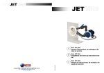
JET
JET
F
GB
15 rue des Marais - 44310 SAINT PHILBERT DE GRAND LIEU - France
Tél. : 02 40 59 95 35 - Fax : 02 40 59 94 91
[email protected]
ACIS 12/01/2011
E
JET VAG - Pièce à sceller pour piscine
BETON, PANNEAU et BOIS
Manuel d’instructions, de montage et de
mise en service
JET VAG - Flow fitting for CONCRETE,
WOOD swimming-pool or with PANELS
Installation and start-up instruction
manual
JET VAG - Accesorio empotable para piscina HORMIGÓN, PANEL y MADERA
Manual de instrucciones, de montaje y de
puesta en servicio
JET
Turn your swimming pool into a fun
and pleasurable place by installing the
JETVAG with its revolutionary design.
JETVAG is attractive, easy to use,
reliable, high-performance and costeffective. The single-body flow fitting
centralises the air and water flows on
one adjustable nozzle. Patented system.
En installant le nouvel appareil JETVAG, de conception révolutionnaire,
votre piscine devient un lieu d’attraction et de plaisir. JETVAG est esthétique, simple, fiable, performant et
économique. Sa pièce à sceller ou à
fixer monocorps centralise sur une
même buse orientable le débit de l’air
et le débit de l’eau. Système breveté.
Take the time to read this installation
and startup instruction manual in
order to make the most of your JETVAG.
Prenez le temps de lire ce manuel
d’installation et de mise en service
afin de pouvoir profiter pleinement de
votre nouveau JETVAG.
Box contents
Inside your box, you will find all the
parts you need to install the flow
fitting in a concrete, vinyl liner or
polyester swimming pool.
Contenu du colis
A l’intérieur de votre colis, vous
trouverez toutes les pièces nécessaires à l’installation de votre pièce à
sceller pour les piscines.
Ø63 flow fitting (photo 1): one
carton containing:
- this technical booklet
- 2 Ø63 valves
- 1 protection plate
- 1 screw kit
- 1 flow fitting with pipes
- 2 seals
OR
Ø90 flow fitting (photo 2): one
carton containing:
- this technical booklet
- 2 Ø63 valves
- 1 protection plate
- 1 screw kit
- 1 flow fitting with pipes and 2
75x90 glued-on reducers
- 2 90x63 reducers
- 2 couplers FF Ø90
- 2 seals
Pièce à sceller Ø63 (photo1) : un
carton comprenant :
- ce livret technique
- 2 vannes Ø63
- 1 plaque de protection
- 1 kit vis
- 1 pièce à sceller avec tuyaux
- 2 joints
OU
Pièce à sceller Ø90 (photo2) : un
carton comprenant :
- ce livret technique
- 2 vannes Ø63
- 1 plaque de protection
- 1 kit vis
- 1 pièce à sceller avec tuyaux
et 2 réductions collées 75x90
- 2 réductions 90x63
- 2 manchons FF Ø90
- 2 joints
JET
Con la instalación del nuevo aparato
JETVAG, que presenta un diseño
revolucionario, su piscina se convertirá en un lugar atractivo y placentero.
JETVAG es estético, sencillo, fiable,
eficaz y económico. Su accesorio
empotrable monocuerpo centraliza en
una misma boquilla orientable el
caudal de aire y de agua. Sistema
patentado.
Tómese el tiempo de leer este manual
de instalación y de puesta en servicio
para poder disfrutar plenamente de
su nuevo JETVAG.
Contenido del paquete
En el interior del paquete encontrará todas las piezas necesarias
para la instalación del accesorio
empotrable para las piscinas de
hormigón, liner y poliéster.
Accesorio empotrable Ø63 (foto 1):
una caja que contiene:
- este folleto técnico
- 2 válvulas Ø63
- 1 placa de protección
- 1 kit de tornillos
- 1 accesorio empotrable con tubos
- 2 juntas
O
Accesorio empotrable Ø90 (foto 2):
una caja que contiene:
- este folleto técnico
- 2 válvulas Ø63
- 1 placa de protección
- 1 kit de tornillos
- 1 accesorio empotrable con tubos
y 2 piezas de reducción encoladas
75x90
- 2 piezas de reducción 90x63.
- 2 manguitos FF Ø90
- 2 juntas
n°
Désignation
Description
Denominación
1
Pièce à sceller
Flow fitting
Accesorio empotrable
2
Bride
Flange
Brida
3
Plaque de protection
Protection plate
Placa de protección
4
Joint adhésif
Adhesive seal
Junta adhesiva
5
Kit vis pièce à sceller
Screw kit
Kit de tornillos
6
Vannes Ø63
Gates Ø63
Válvulas Ø63
7
Manchon Ø90
Coupler Ø90
Manguito Ø90
8
Réduction Ø90/Ø75
Reduction Ø90/Ø75
Reducción Ø90/Ø75
9
Réduction Ø63/Ø90
Reduction Ø63/Ø90
Reducción Ø63/Ø90
Photo1
Photo2
2
7
JET
JET
1. INSTALLING THE FLOW FITTING
The flow fitting (photo 3) must be
installed at least 30 cm from the
water level. Make sure that it is
installed the right way round.
1. INSTALLATION DE LA PIECE
A SCELLER
La pièce à sceller (photo3) doit être
installée à une distance minimale de
30 cm par rapport au niveau de
l’eau. Attention à la partie Haute et
Basse.
1. INSTALACIÓN DEL ACCESORIO EMPOTRABLE
El accesorio empotrable (foto 3)
debe instalarse a una distancia
mínima de 30 cm con respecto al
nivel del agua. Preste atención a la
parte Alta y Baja.
1
Niveau de l’eau / Water
level / Nivel del agua
30cm mini / 30cm
como mínimo
2
Photo3
3
1.1 CUT-OUT:
If the hole for installing the flow
fitting has not been made, please
refer to the drawing below.
1.1 DECOUPE :
Si le trou pour l’installation de la
pièce à sceller n’est pas fait, veuillez
vous reporter au plan ci-dessous.
1.1 CORTE:
El orificio para la instalación del
accesorio empotrable no se ha
realizado, remítase al siguiente
plano.
4
5
R=140 mm
6
270 mm
10 mm
.
R=140 mm
237 mm
7
8
9
6
Pour/For/Para Ø90
Please ensure the correct distance
in relation to the water level and
ensure that the installation is parallel to the structure.
Veuillez respecter la distance par
rapport au niveau de l’eau et que
l’installation soit bien parallèle à la
structure
Respete la distancia con respecto al
nivel del agua y que la instalación
sea perfectamente paralela a la
estructura.
3
JET
1.2 INSTALLATION:
STEP 1:
For concrete pools:
Install the flow fitting the right way
round on the bare concrete. Note:
for 90 mm dia. installations, check
that the shuttering embeds the
couplers fully, to avoid any cement
entering the joint. You may pour the
concrete.
For other types of pool:
Position the flow fitting the right
way round. Fit it using the four
screws.
1.2 INSTALLATION :
ETAPE 1 :
Pour les piscines béton :
Installer votre pièce à sceller dans le
bon sens à la rase du béton. Attention, pour les installations en Ø90,
vérifier que le coffrage encastre
bien les manchons afin d’éviter
toute infiltration. Vous pouvez couler le béton.
Pour les autres types de piscines :
Positionner votre pièce à sceller
dans le bon sens. La fixer à l’aide
des 4 vis.
JET
1.2 INSTALACIÓN:
ETAPA 1:
Para las piscinas de hormigón:
Instalar su accesorio empotrable en
el sentido correcto a ras del hormigón. Atención, para las instalaciones de Ø90, comprobar que el
encofrado encastre bien los manguitos para evitar toda infiltración.
Usted puede colar el hormigón.
Para los otros tipos de piscinas:
Colocar su accesorio empotrable en
el sentido correcto. Fijarlo con 4
tornillos.
Fit the protection plate onto the
flow fitting using the 3 M5 screws.
Monter la plaque de protection sur
la pièce à sceller à l’aide des 3 vis
M5.
Monte la placa de protección en el
accesorio empotrable con 3 tornillos
M5.
STEP 2: For the vinyl liner swimming pools EXCLUSIVELY: Clean
and then glue the seal onto the
front of the flow fitting. After this
step, the liner must be fitted.
ETAPE 2 : Pour les piscines Liner
EXCLUSIVEMENT : Nettoyer puis
coller le joint sur le devant de la
pièce à sceller. A partir de cette
étape, le pose du liner est à faire.
ETAPA 2: Para las piscinas de liner
EXCLUSIVAMENTE: limpie y, a
continuación, encole la junta en la
parte delantera del accesorio empotrable. A partir de esta etapa, debe
realizarse la colocación del liner.
STEP 3: For vinyl liner and Polyester swimming pools: Fill the swimming pool up to the lower part of
the flow fitting and put the liner
flange and the 12 screws in place
(NB: It is easy to make holes in the
liner using the screws). Tighten
sufficiently so that the seal(s) is
(are) flattened.
ETAPE 3 : Pour les piscines Liner et
Polyester : Remplir la piscine jusqu’au niveau inférieur de la pièce à
sceller et mettre la bride liner et les
12 vis (NB : le liner se percera
facilement avec les vis). Serrer
suffisamment pour que le(s) joint(s)
s’aplatisse(nt).
4
STEP 4: For the vinyl liner swimming pools EXCLUSIVELY: Cut out
the liner (lower part of the liner
flange).
ETAPE 4 : Pour les piscines Liner
EXCLUSIVEMENT : Faire une découpe du liner (partie intérieure de la
bride liner).
ETAPA 4: Para las piscinas de liner
EXCLUSIVAMENTE: realice un corte
del liner (parte interior de la brida
liner).
Important note: The addition to
the flow fitting will be supplied with
a 63 mm diameter, max. length 3
m. For longer distances, we advise
you to fit 2 x 63 mm dia. or 90 mm
dia. pipework. Refer to the instructions for the addition to the flow
fitting.
Remarque importante : Le complément à la pièce à sceller vous
sera livré en Ø63, longueur maxi
3m. Pour une distance supérieure,
nous vous conseillons un montage
en 2xØ63 ou sinon avec une canalisation en Ø90. Se reporter à la
notice du complément à la pièce à
sceller.
Observación importante:
El complemento al accesorio empotrable se le suministrará en Ø63,
longitud máxima de 3 m. Para una
distancia superior, le aconsejamos
un montaje en 2xØ63 o, de lo contrario, con una canalización de Ø90.
Remitirse a la instrucción del complemento al accesorio empotrable.
ETAPA 3: Para las piscinas de liner
y poliéster: llene la piscina hasta el
nivel inferior del accesorio empotrable y coloque la brida liner y los 12
tornillos (nota: el liner se perforará
fácilmente con los tornillos). Apriete
lo suficiente como para que la(s)
junta(s) se aplane(n).
5