1
INSTALLATION
PREPARING THE BASE
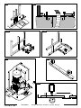
The product may only be installed by a qualified fitter. The manu- Dig foundations at least 15 cm deep and sufficiently wide. Use
facturer, Tau, declines all liability for damage to property and/or in- protective sheaths for the cables.
jury to people deriving from the incorrect installation of the system
or its noncompliance with current law (see Machinery Directive).
Fill the hole with concrete and sink the bet pins into it; the counterplate must be perfectly flat at 1 or 2 cm from the level of the
finished floor and at a distance of approximately 65 mm from the
gate.
NB: it is also possible to install the gear motor without the foundation counterplate by using four foundation bolts on a flat concrete
base; the measurements shown in fig. 9 must always be respected.
A height-adjustable counterplate may be used for models BIG12
and BIG18; in this case, the fixed bent pins must be welded to the
rail, see fig. 12/a.
This makes it possible to adapt the gear motor to a pre-existing
system; the measurements shown in fig. 12/b must be respected.
FIG. 2 - INSTALLATION MATERIAL
1. gear motor
2. counterplate
3. rack
4. self-tapping screws
5. limit switch shoes
6. release key
7. rack brackets
8. bent pins for counterplate
ANCHORING THE GEAR MOTOR
Tighten the screws (as shown in fig. 13) on both sides of the gear
motor. Fit all the cables into the sheath, which passes through the
hole made in the base of the foundation counterplate.
FIXING THE RACK
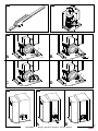
Prepare the rack with the relative brackets (fig. 14).
Place the rack on the motor pinion (released) respecting the disPlace the control unit (external versions) in the immeditance between the tooth of the gear and the tooth of the rack as
ate vicinity of the motors.
shown in fig. 15. Make a hole in the leaf at the centre of the slot
Be careful not to run cables for auxiliary devices in- and fix with the relative screws. Slide the leaf along the pinion and
side raceways housing other cables supplying power fix each bracket in turn.
to large loads or lights with electronic starters.
In the event control pushbuttons or indicator lights are
installed inside homes or offices several metres from
the actual control unit, it is advisable to decouple the
signal by means of a relay in order to avoid induced
interference.
FIXING AND ADJUSTING THE LIMIT SWITCH SHOES
Fix the shoes as shown in fig. 16, one near either end of the rack.
Move the leaf by hand and position the shoes so that they touch
the microswitch lever just before the leaf hits the travel stops at
both ends of the rail; then tighten the screws.
A single factor or combination of factors (thermal expansion, climate, frequency of use, etc.) may result in
the position the gate stops in changing over the course
of the day, both when opening and when closing. Consequently, we cannot guarantee that the gate will always stop in the same position.
OVERALL DIMENSIONS
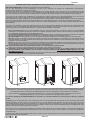
Figs. 3,4,5 show the main overall dimensions for the sliding gate;
figs.6-7 show the dimensions of the foundation counterplate, while
fig.8 shows the dimensions of the adjustable counterplate for models BIG12 and BIG18.
PRELIMINARY OPERATIONS
Carefully read the instructions contained in the handbook before
starting work.
Before proceeding with installation, make sure that all the components are present, use suitable work equipment and do not touch
live electrical parts.
ADJUSTING THE MECHANICAL CLUTCH
Before starting, make sure to disconnect the gear motor from the
power supply.
BIG12-18: Make a 1/2 or a whole turn at a time using the supplied wrench (fig. 17).
BIG30-40: After removing the lock nut (1 fig. 18A) and the stop
dowel (2 fig. 18A), adjust the thrust force using the
hex wrench provided (3 fig. 18B) (rotate clockwise to
CONSIDERATIONS PRIOR TO INSTALLATION
increase the thrust force, rotate counter-clockwise
Before proceeding with installation check that:
to decrease it). After adjusting as needed, reas- The wheels of the gate are mounted in such a way as to make
semble the stop dowel (2 fig. 18D) until it reaches
it stable and that they are in good condition and perfect working
the mechanical stop, then fasten the lock nut (1 fig.
order;
18D).
- The whole of the slide rail is unobstructed, straight and clean
and a travel stop is fitted at either end.
ELECTRICAL CONNECTIONS
For electrical connection, please refer to the specific instructions
for each electrical control panel. The following tips apply to all modTo install the gear motor correctly, make sure it is at a distance of els.
Do not put the power cables in the same sheath as the motor ca65 mm from the gate.
See fig. 09 for fixing to a concrete floor, fig. 10 for digging and fig. bles. Always choose the shortest routes for the cable lines. Make
sure the equipment is well earthed. A general switch should be
11 for positioning the counterplate.
fitted to the system, out of reach of unauthorised people, allowing
power to be disconnected from the gear motor for maintenance
purposes or if the gear motor remains inactive for a long period.
INSTALLATION DISTANCES
BIG Series
11
ENGLISH
FIXING THE FOUNDATION COUNTERPLATE
FIG. 1 - STANDARD SYSTEM
1. Gear motor
2. Release
3. Photocells
4. Posts + Photocells
5. Aerial and Flashing light
6. Key switch
7. Electromechanical edge
8. Gate guide
9. Limit switch shoe
10. Rack