1
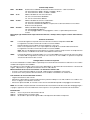
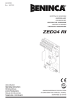
L8542336
Rev. 07/04/02
CENTRALE DI COMANDO
CONTROL UNIT
STEUEREINHEIT
CENTRALE DE COMMANDE
CENTRAL DE MANDO
CENTRALKA STEROWANIA
MBE
Libro istruzioni
Operating instructions
Betriebsanleitung
Livret d’instructions
Manual de instrucciones
Książeczka z instrukcjami
UNIONE NAZIONALE COSTRUTTORI
AUTOMATISMI PER CANCELLI, PORTE,
SERRANDE ED AFFINI
Dichiarazione CE di conformità
EC declaration of confirmity
EG-Konformitatserklarung
Déclaration CE de conformité
Declaracion CE de conformidad
Deklaracja UE o zgodności
Con la presente dichiariamo che il nostro prodotto
We hereby declare that our product
Hiermit erklaren wir, dass unser Produkt
Nous déclarons par la présente que notre produit
Por la presente declaramos que nuestro producto
Niniejszym oświadczamy że nasz produkt
MBE
è conforme alle seguenti disposizioni pertinenti:
complies with the following relevant provisions:
folgenden einschlagigen Bestimmungen entspricht:
correspond aux dispositions pertinentes suivantes:
satisface las disposiciones pertinentes siguientes:
zgodny jest z poniżej wyszczególnionymi rozporządzeniami:
Direttiva sulla compatibilità elettromagnetica (89/336/
CCE, 93/68/CEE)
EMC guidelines (89/336/EEC, 93/68/EEC)
EMV-Richtlinie (89/336/EWG, 93/68/EWG)
Directive EMV (89/336/CCE, 93/68/CEE) (Compatibilité
électromagnétique)
Reglamento de compatibilidad electromagnética (89/336/
MCE, 93/68/MCE)
Wytyczna odnośnie zdolności współdziałania elektromagnetycznego (89/336/EWG, 93/68/EWG)
Direttiva sulla bassa tensione (73/23/CEE, 93/68/CEE)
Low voltage guidelines (73/23/EEC, 93/68/EEC)
Tiefe Spannung Richtlinie (73/23/EWG, 93/68/EWG)
Directive bas voltage (73/23/CEE, 93/68/CEE)
Reglamento de bajo Voltaje (73/23/MCE, 93/68/MCE)
Wytyczna odnośnie niskiego napięcia (73/23/EWG, 93/
68/EWG)
Norme armonizzate applicate in particolare:
Applied harmonized standards, in particular:
Angewendete harmonisierte Normen, insbesondere:
Normes harmonisée utilisées, notamment:
Normas armonizadas utilzadas particularmente:
Normy standard najczęściej stosowane:
Norme armonizzate applicate in particolare:
Applied harmonized standards, in particular:
Angewendete harmonisierte Normen, insbesondere:
Normes harmonisée utilisées, notamment:
Normas armonizadas utilzadas particularmente:
Normy standard najczęściej stosowane:
EN 55022, EN 61000-3-2, EN 61000-3-3, EN 50082-1
EN 60204-1, EN 60335-1
Data/Firma
Data/Firma
Automatismi Benincà SpA
Via Capitello, 45
36066 Sandrigo (VI)
ITALIA
2
# Ingresso pulsante pedonale
# Input, pedestrian entrance push-button
# Eingang, Fußgängereingang Taste
# Entrée bouton entrée piétonne
# Entrada pulsador entrada de peatones
# Wejście dla przycisku nożnego
0 NT
0
120
12
155 POWER
24
190
230 FT
SHIELD
N.O.
P.P.
N.C.
STOP
FTC
N.C.
D5
3 4 5 6 7 8 9 10 11
SCA
24Vac
3W max
RADIO
1 2
ANT
ANT
+V
24Vac
0,5A max
ELS
12Vac
D4
PGM
1 P.P. Mod
2 C.A.
3 Cond.
4 Prelamp.
24V 12V 0V Power NT FT
12 13 14 15 16 17
D2
F2 2A
F1 6.3A
18
19 20 21
L
230VAC
50Hz
N
22 23 24 25 26
COM
LAMP
230Vac
C
MB
C
MBE
3
Centrale di comando per MBE
La centrale elettronica MBE può essere utilizzata per il controllo di 1 o 2 motori MB/MBE.
AVVERTENZE GENERALI
a) L’installazione elettrica e la logica di funzionamento devono essere in accordo con le normative vigenti.
b) I conduttori alimentati con tensioni diverse, devono essere fisicamente separati, oppure devono essere
adeguatamente isolati con isolamento supplementare di almeno 1 mm.
c) I conduttori devono essere vincolati da un fissaggio supplementare in prossimità dei morsetti.
d) Ricontrollare tutti i collegamenti fatti prima di dare tensione.
e) Controllare che le impostazioni dei Dip-Switch siano quelle volute.
f) Gli ingressi N.C. non utilizzati devono essere ponticellati.
FUNZIONI INGRESSI/USCITE
N° Morsetti
Funzione
Descrizione
1
ANT
Segnale Antenna.
2
SHIELD
Schermo Antenna.
3-8
SCA
Collegamento spia cancello aperto 24 Vac/3W max.
4
Passo-Passo
Ingresso pulsante passo-passo N.O.
5
STOP
Ingresso pulsante STOP N.C.
6
FTC
Ingresso collegamento dispositivi di sicurezza, contatto N.C. (ad es. fotocellule)
7
+V
Comune per tutti gli ingressi di comando.
8-9
24 Vac
Uscita alimentazione accessori 24Vac/0,5A max.
10-11
ELS
Collegamento elettroserratura 12Vac/0,5A max.
12-13-14
24-12-0
Collegamento avvolgimento secondario trasformatore
15-16-17
POWER-NT-FT
Collegamento avvolgimento primario trasformatore
18-19
Alimentazione
Ingresso 230 Vac 50Hz (18-fase/19-neutro)
20-21
LAMP
Uscita collegamento lampeggiante 230Vac 40W max.
22-23-24
Motore MB
Collegamento al motore MB (senza centrale di comando):
(22-marcia/23-marcia/24 com)
24-25-26
Motore MBE
Collegamento al motore MBE (con centrale di comando):
(24-com/25-marcia/26 marcia)
#
Pedonale
Se si desidera utilizzare l’ingresso pedonale collegare un pulsante normalmente aperto (N.O.) tra +V (comune dei comandi) ed il piolino posto vicino
al morsetto STOP (vedi schema).
Verifica collegamenti:
Dopo aver regolato i finecorsa come indicato nel manuale istruzioni dell'attuatore, procedere come segue:
1) Togliere alimentazione.
2) Sbloccare manualmente le ante, portarle a circa metà della corsa e ribloccarle.
3) Ripristinare l’alimentazione.
4) Dare un comando di passo-passo mediante pulsante o radiocomando.
5) Le ante devono muoversi in apertura. Nel caso ciò non avvenisse, è sufficiente invertire tra loro i fili di marcia
del motore. (22/23 per il motore MB, e 25/26 per il motore MBE).
6) Procedere con la regolazione dei Tempi e delle Logiche di funzionamento e della potenza motore.
Regolazione della potenza motore
ATTENZIONE! Questa regolazione influisce sul grado di sicurezza dell’automazione.
Verificare che la forza applicata sull’anta sia conforme con quanto previsto dalle normative vigenti.
Sul trasformatore di alimentazione è presente un connettore Faston (POWER) che permette la regolazione della
potenza dei motori su 3 diversi livelli.
Posizionando il Faston (POWER) su 120 si ha la potenza minore, spostandolo su 190 si ha la potenza maggiore.
ATTENZIONE!: Non essendo l'attuatore MB/MBE dotato di frizione meccanica regolabile, il faston POWER non
deve mai essere portato in posizione 230V.
4
Funzione Dip-Switch
DIP 1
“P.P. Mod”
Seleziona la modalità di funzionamento del ”Pulsante P.P.” e del trasmettitore.
Off: Funzionamento: APRE > STOP > CHIUDE > STOP >
On: Funzionamento: APRE > CHIUDE > APRE >
DIP 2
“C.A.”
Abilita o disabilita la chiusura automatica.
Off: chiusura automatica disabilitata
On: chiusura automatica abilitata
DIP 3
“Cond.”
Abilita o disabilita la funzione condominiale.
Off: Funzione condominiale disabilitata.
On: Funzione condominiale abilitata. L’impulso P.P. o del trasmettitore non ha effetto
durante la fase di apertura.
DIP 4
“Prelam.”
Abilita o disabilita il prelampeggio
Off: Prelampeggio disabilitato
On: Prelampeggio abilitato. Il lampeggiante si attiva 3 s prima della partenza del
motore.
Nota: Dopo ogni modifica delle impostazioni dei trimmer e dei Dip-switch, togliere e ridare alimentazione
di rete.
Funzione dei Trimmer
TCA
Permette di regolare il tempo di chiusura automatica. Verificare il Dip-Switch N°2= On.
La regolazione varia da un minimo di 1 s ad un massimo di 125 s
TL
Regola la durata massima della manovra di apertura e chiusura.
Deve essere impostato circa 4 sec. in più rispetto al tempo di corsa effettiva dell’automatismo.
La regolazione varia da un minimo di 5 s ad un massimo di 130 s
Nota: Nel caso di apertura/chiusura parziale, la centrale calcola il tempo restante al completamento
della manovra, in modo da evitare inutili surriscaldamenti del motore.
TRAC
Permette di regolare il tempo di ritardo con cui il motore MBE inizia la manovra di chiusura rispetto
al motore MB. La regolazione varia da un min. di 3 s a un max. di 30 s. In apertura il tempo di
sfasamento dei motori è di 2 secondi.
Configurazione ricevitore incorporato
La centrale è dotata di un modulo radio incorporato per la ricezione di telecomandi sia a codice fisso che a codice
variabile alla frequenza di 433.92MHz.
Per utilizzare un telecomando è prima necessario apprenderlo, la procedura di memorizzazione è illustrata di
seguito, il dispositivo è in grado di memorizzare fino a 14 codici diversi.
Memorizzazione di un nuovo trasmettitore con attivazione funzione P.P.
- Premere 1 volta il pulsante PGM per 2 secondi, il led D4 inizia a lampeggiare velocemente.
- Premere entro 10s il pulsante del trasmettitore che si desidera memorizzare con funzione P.P.
Cancellazione dei telecomandi dalla memoria
- Togliere alimentazione alla centrale
- Ripristinare l’alimentazione mantenendo premuto il pulsante PGM per 5 secondi, il led D4 si accende a luce
fissa e si spegne a cancellazione avvenuta.
- Rilasciare il pulsante PGM, la memoria è stata cancella ed il LED D4 riprende a lampeggiare normalmente.
NOTA: Se entrando nella procedura di memorizzazione dei trasmettitori il LED D4 emette due lampeggi lunghi e
si spegne, significa che la memoria della ricevente è piena e non è possibile memorizzare altri trasmettitori.
Funzioni LED
LED D2
Acceso in presenza alimentazione di rete
LED D4
Programmazione ricevitore radio
LED D5
Si accende in presenza di segnali radio sulla frequenza del modulo incorporato.
5
MBE control unit
The electronic control unit MBE can be used to control 1 or 2 motors MB/MBE.
GENERAL WARNINGS
a) The wire connections and the operating logic should be in compliance with regulations in force.
b) The cables featuring different voltage should be physically detached, or adequately insulated by an additional
insulation of at least 1 mm.
c) The cables should be further fastened in proximity to the terminals.
d) Check all connections before powering the unit.
e) Check that settings of the Dip-switches are the required ones.
f) The N.C. inputs which are not in use should be short-circuited.
INPUT/OUTPUT FUNCTIONS
Terminal No.
Function
Description
1
ANT
Antenna Signal
2
SHIELD
Antenna Shield
3-8
SCA
Indicator lamp, Open gate
4
P-P
Input, N.O. step-by-step push-button
5
STOP
Input, N.C. STOP push-button
6
FTC
Input, safety devices connection, N.C. terminal (e.g. photocells)
7
+V
Common to all control inputs.
8-9
24 Vac
Output, accessories power supply 24Vac/0,5 A max.
10-11
ELS
Electric lock connection, 12Vac/0,5A max.
12-13-14
24-12-0
Connection to transformer secondary winding
15-16-17
POWER-NT-FT
Connection to transformer primary winding
18-19
Power supply
Input, 230Vac 50Hz (18-Phase/19-Neutral)
20-21
LAMP
Output, flashing light connection, 230Vac 40W max.
22-23-24
MB Motor
Connection to MB motor (without control unit):
(22-movement/23-movement/24 com)
24-25-26
MBE Motor
Connection to MBE motor (with control unit):
(24-com/25-mouvement/26 movement)
#
Pedestrian
To use the pedestrian entrance, connect the normally open (N.O.) pushbutton between +V (control common) and the little knob near terminal
STOP (see wire diagram).
To check connections:
After adjusting the limit switches as shown in the actuator instruction manual, proceed as follows:
1) Cut-off power supply.
2) Manually release the wings, move them to approx. half-stroke and lock them again.
3) Reset power supply.
4) Send a step-by-step control signal by pressing the button or the remote control key.
5) The wings should start an opening movement. If this is not the case, invert the movement wires of the motor.
(22/23 for motor MB, and 25/26 for motor MBE).
6) Adjust Time, Operating Logic and Motor Power.
To adjust the motor power
WARNING! This adjustment affects the safety of the automatic system.
Check that the thrust applied onto the wing complies with regulations in force.
A Faston (POWER) connector is provided on the power supply transformer which allows the power adjustment
of the motors on 3different levels. By moving the Faston (POWER) to 120, power is at minimum, by moving it to
190, power is at maximum.
WARNING! : As the MB/MBE actuator is not equipped with adjustable mechanical clutch, the POWER faston
must never be moved to 230V position.
6
Dip-Switch functions
DIP 1
“P.P. Mod”
The operating mode of ”Pulsante P.P.” (Step-by-step push button) and of the transmitter
is selected.
Off: operation : APRE > STOP > CHIUDE > STOP >
On: operation: APRE > CHIUDE > APRE >
DIP 2
“C.A.”
Automatic closure is enabled or disabled.
Off: disabled automatic closure
On: enabled automatic closure
DIP 3
“Cond.”
The multi-flat function is enabled or disabled.
Off: disabled multi-flat function.
On: enabled multi-flat function. The P.P. (Step-by-step) impulse or the impulse of the
transmitter have no effect in the opening phase.
DIP 4
“Prelam.”
Forewarning flashing light enabled or disabled
Off: disabled forewarning flashing light
On: enabled forewarning flashing light. The flashing light is activated 3 s before the motor
starts.
Note: After modifying the setting of trimmers and Dip-Switches, switch off and power the unit again.
Functions of Trimmers
TCA
TL
TRAC
The automatic closure time can be adjusted with this trimmer. Check Dip-switch N°2= On.
This function can be adjusted between 1 s minimum and 125 s maximum
The maximum time of the opening and closing phases can be adjusted with this trimmer.
Time should be preset approx. 4 sec. longer than the actual stroke time of the automatic system.
Adjustment ranges from 5 s minimum to 130 s maximum
Note: In the event of partial opening/closing, the control unit calculates the remaining time to
complete the operation in order to avert useless overheating of the motor.
It allows to adjust the delay time with which motor MBE starts closing with respect to motor MB.
Adjustment range from 3 s minimum to 30 s maximum. During opening, the out of phase time of the
motors is 2 seconds.
Configuration of the built-in receiver
The control unit is complete with an incorporated radio receiver for both fixed-code and variable code radio
controls, at 433.92MHz frequency.
To use a radio control, its code should be copied first. The memorization procedure is shown here under. The
device is able to store up to 14 different codes in memory.
Memorization of a new transmitter with activation of the P.P. (step-by-step) function
- Press PGM button once for 2 seconds, the D4 LED starts flashing rapidly.
- Within 10s, press the transmitter push-button which should be stored in memory with P.P. function.
To delete the control unit codes from memory
- Cut-off power supply to the control unit
- Reset power supply by keeping the PGM button pressed for 5 seconds; the D4 LED switches on with fixed
light and then off when deletion is completed.
- Release the PGM button, memory is deleted and the D4 LED starts flashing regularly again.
NOTE: If the D4 LED switches on with two long flashes and then switches off, when entering the transmitter
codes memorization mode, this means that the receiver is full and no other transmitter code can be stored in
memory.
LED functions
LED D2
Access when the unit is powered
LED D4
Radio receiver programming
LED D5
This LED switches on when radio signals are received on the built-in module frequency.
7
Steuerung für ”MBE”
Die elektronische Zentrale MBE kann zur Steuerung von 1 oder 2 Motoren MB/MBE verwendet werden.
ALLGEMEINE HINWEISE
a) Die elektrische Installation und die Betriebslogik müssen den geltenden Vorschriften entsprechen.
b) Die Leiter die mit unterschiedlichen Spannungen gespeist werden müssen physisch getrennt oder
sachgerecht mit einer zusätzlichen Isolierung von mindestens 1 mm isoliert werden.
c) Die Leiter müssen in der Nähe der Klemmen zusätzlich befestigt werden.
d) Alle Anschlüsse nochmals prüfen, bevor die Zentrale mit Strom versorgt wird.
e) Kontrollieren, ob die Dip-Schalter richtig positioniert sind.
f) Die nicht verwendeten N.C. Eingänge müssen überbrückt werden.
FUNKTIONEN EINGÄNGE/AUSGÄNGE
Anzahl
Klemmen
Funktion
Beschreibung
1
ANT
Antennensignal
2
SHIELD
Antennenabschrimung
3-8
SCA
Anschluss Meldeleuchte Tor offen 24 Vac/3W max.
4
P-P
Eingang Schritt-Schritt-Taste N.O.
5
STOP
Eingang Taste STOP N.C.
6
FTC
Eingang Anschluss Sicherheitsvorrichtungen, Kontakt N.C. (z.B. Fotozellen)
7
+V
Allgemein für alle Steuerungseingänge.
8-9
24 Vac
Ausgang Speisung Zubehör 24Vac/0,5A max.
10-11
ELS
Anschluss an das Elektroschloss 12Vac/0,5A max.
12-13-14
24-12-0
Anschluss Wicklung sekundäres Trafo
15-16-17
POWER-NT-FT
Anschluss Wicklung primäres Trafo
18-19
Speisung
Eingang 230Vac 50Hz (1-Phase/2-Nulleiter)
20-21
LAMP
Ausgang Anschluss Blinkleuchte 230Vac 40W max.
22-23-24
Motor MB
Anschluss an den Motor MB (ohne Steuereinheit):
(22-Betrieb/23-Betrieb/24 com)
24-25-26
Motor MBE
Anschluss an den Motor MBE (mit Steuereinheit):
(24-com/25-Betrieb/26 Betrieb)
#
Fußgänger
Will man den Fußgängereingang verwenden, die Taste N.O. zwischen
+V (allgemein für Steuerungen) und der Sprosse in der Nähe der Klemme
STOP (siehe Plan) anschließen.
Anschlüsse überprüfen:
Nachdem die Endschalter laut Anweisungen des Aktuatoren-Handbuchs eingestellt worden sind,
folgendermaßen vorgehen:
1) Stromversorgung abtrennen.
2) Von Hand die Torflügel entsichern, bis auf halbem Hub führen und wieder blockieren.
3) Wieder Strom geben.
4) Einen Schritt-Schritt-Befehl über die Taste oder die Fernsteuerung geben.
5) Die Torflügel müssen sich öffnen. Anderenfalls die Leiter für den Betrieb des Motors (22/23 für den Motor
MB, und 25/26 für den Motor MBE) umkehren.
6) Nun Zeiten, Betriebslogik und Motorleistung einstellen.
Motorleistung einstellen
ACHTUNG! Diese Einstellung hat Einfluss auf die Sicherheit der Automatik.
Die für das Tor angewendete Kraft muss den geltenden Vorschriften entsprechen.
Der Speisetrafo ist mit einem Faston (POWER) Verbinder versehen, durch den die Motorleistung auf 3
verschiedene Stufen eingestellt werden kann. Wird der Faston (POWER) Verbinder auf 120 eingestellt, wird
die Motorleistung auf das Minimum geregelt; wird er auf 190 eingestellt, wird die maximale Motorleistung
erreicht.
ACHTUNG!: Da der Aktuator MB/MBE nicht mit einer einstellbaren mechanischen Kupplung ausgestattet ist,
darf der Faston POWER niemals auf die Position 230V positioniert werden.
8
Dip-Schalter-Funktionen
DIP 1
“P.P. Mod”
Wählt die Betriebsart der „Taste P.P.“ und des Sendegeräts.
Off: Betrieb: ÖFFNEN > STOPP > SCHLIESSEN > STOPP
On: Betrieb: ÖFFNEN > SCHLIESSEN > ÖFFNEN
DIP 2
“C.A.”
Aktiviert oder deaktiviert den automatischen Schließvorgang.
Off: automatischer Schließvorgang deaktiviert
On: automatischer Schließvorgang aktiviert
DIP 3
“Cond.”
Aktiviert oder deaktiviert die Funktion Wohngemeinschaft.
Off: Funktion Wohngemeinschaft deaktiviert.
On: Funktion Wohngemeinschaft aktiviert. Auf den Öffnungsvorgang haben weder der
Schritt-Schritt-Impuls noch der Impuls des Sendegeräts Einfluss.
DIP 4
“Prelam.”
Aktiviert oder deaktiviert das Vorblinken.
Off: Vorblinken deaktiviert
On: Vorblinken aktiviert. Das Vorblinken beginnt 3 sec. vor dem Einschalten des Motors.
Bemerkung: Nach jeder Änderung der Trimmer- und Dip-Schalter-Einstellungen, das Gerät stromlos machen und
dann wieder an das Stromnetz anschließen.
Trimmer-Funktionen
TCA
TL
TRAC
Ermöglicht es die Zeit des automatischen Schließvorgangs einzustellen.
Kontrollieren ob Dip-Schalter Nr. 2= On.
Die Zeit kann zwischen 1 sec. und maximal 125 sec. eingestellt werden.
Stellt die maximale Zeit des Öffnungs- und Schließvorgangs ein.
Die Zeit muss ungefähr 4 sec. länger sein als die die für den tatsächlichen Hub der Automatik
benötigt wird.
Die Zeit kann zwischen 0 sec. und maximal 130 sec. eingestellt werden.
Bemerkung: bei unvollständigem Öffnungs-/Schließvorgang rechnet die Zentrale die restliche
Zeit bis zur Vervollständigung der Bewegung aus, um den Motor nicht unnötig zu belasten und zu
überhitzen.
Ermöglicht es die Verzögerung mit welcher der Motor MBE den Flügel im Verhältnis zum Motor
MB schließt, einzustellen. Die Zeit kann zwischen 3 s und max. 30 sec. eingestellt werden. Beim
Öffnen beträgt der Unterschied zwischen den Motoren 2 Sekunden.
Konfiguration des eingebauten Empfängers
Die Zentrale ist mit einem eingebauten Funkmodul für den Empfang von Fernbedienungen mit festem Code
und mit variablen Code, mit einer Frequenz von 433.92MHz ausgestattet.
Um eine Fernbedienung verwenden zu können, muss diese zuerst erlernt werden; die Speicherungsprozedur
ist nachstehend beschrieben. Das Gerät kann bis zu 14 unterschiedliche Codes speichern.
Speicherung eines neuen Sendegeräts mit Aktivierung der Schritt-Schritt-Funktion
- 1 Mal die Taste PGM 2 Sekunden lang drücken, die Leuchte D4 beginnt schnell zu blinken.
- Innerhalb von 10 sec. die Taste des Sendegeräts drücken, das mit der Schritt-Schritt-Funktion gespeichert
werden soll.
Fernbedienungen aus dem Speicher löschen
- Zentrale stromlos machen
- Wieder Strom geben und gleichzeitig die Taste PGM 5 Sekunden lang gedrückt halten; die Leuchte D4
leuchtet fest und erlischt nach erfolgter Löschung.
- Taste PGM wieder loslassen; nun ist der Speicher leer und die Leuchte D4 blinkt wieder wie üblich.
BEMERKUNG: Wenn die Speicherungsprozedur der Sendegeräte abgerufen wird und die Leuchte D4 zwei
Mal lang blinkt und dann erlischt, bedeutet dies dass der Speicher des Empfängers voll ist und das keine
weiteren Sendegräte gespeichert werden können.
Funktionen der LEUCHTEN
LED D2
Leuchtet bei Stromversorgung
LED D4
Programmierung Funkempfänger
LED D5
Leuchtet bei Funksignalen auf der Frequenz des eingebauten Moduls.
9
Centrale de commande pour MBE
La centrale électronique MBE peut être utilisée pour le contrôle d’un ou de deux moteurs MB/MBE.
AVERTISSEMENTS GENERAUX
a) L’installation électrique et la logique de fonctionnement doivent être conformes aux normes en vigueur.
b) Les conducteurs alimentés avec tensions différentes doivent être séparés physiquement ou adéquatement
isolés avec une isolation supplémentaire d’au moins 1 mm.
c) Les conducteurs doivent être contraints par une fixation supplémentaire à proximité des bornes.
d) Contrôler à nouveau toutes les connexions faites avant de mettre sous tension.
e) Contrôler que les programmations des Dip-Switch sont celles désirées.
f) Les entrées N.C. non utilisées doivent être fixées avec pontets.
FONCTIONS ENTREES/SORTIES
N° Bornes
Fonction
Description
1
ANT
Signal Antenne
2
SHIELD
Blindage Antenne
3-8
SCA
Connexion voyant portail ouvert 24 Vac/3W max.
4
P-P
Entrée touche pas à pas N.O.
5
STOP
Entrée touche STOP N.C.
6
FTC
Entrée connexion dispositif de sécurité, contact N.C. (es. photocellules)
7
+V
Commun pour toutes les entrées de commande.
8-9
24 Vac
Sortie alimentation accessoires 24Vac/0,5A max.
10-11
ELS
Connexion serrure électrique 12Vac/0,5A max.
12-13-14
24-12-0
Connexion enroulement secondaire transformateur
15-16-17
POWER-NT-FT
Connexion enroulement primaire transformateur
18-19
Input 230 Vac
Entrée 230Vac 50Hz (1-Phase/2-Neutre)
20-21
LAMP
Sortie connexion clignotant 230Vac 40W max.
22-23-24
Moteur MB
Connexion au moteur MB (sans centrale de commande):
(22-marche/23-marche/24 com)
24-25-26
Moteur MBE
Connexion au moteur MBE (avec centrale de commande):
(24-com/25-marche/26 marche)
#
Entrée piétonnière
Si on désire utiliser l’entrée piétonnière, connecter un bouton normalement
ouvert (N.O.) entre +V (commun des commandes) et le téton situé près de
la borne STOP (voir schéma).
Vérification des connexions:
Après avoir réglé les fins de course de la manière indiquée dans le manuel d’instructions de l’actionneur, suivre
la marche ci-dessous:
1) Couper le courant.
2) Débloquer manuellement les vantaux, les placer à environ mi-course et les bloquer à nouveau.
3) Restaurer le courant.
4) Donner une commande de pas à pas en appuyant sur la touche ou la radiocommande.
5) Les vantaux doivent se déplacer en ouverture. Au cas contraire, il suffira d’inverser entre eux les fils de vitesse
du moteur. (22/23 pour le moteur MB, e 25/26 pour le moteur MBE).
6) Régler alors les Temps et les Logiques de fonctionnement et de puissance du moteur.
Réglage de la puissance moteur
ATTENTION! Ce réglage influe sur le degré de sécurité de l’automation.
Vérifier que la force appliquée sur le vantail est conforme aux normes en vigueur.
Sur le transformateur d’alimentation il y a un connecteur Faston (POWER) qui permet le réglage de la puissance
de moteurs sur 3 déférents niveaux. En plaçant le Faston (POWER) sur 120 on obtient la puissance mineure,
tandis que sur 190 on a la puissance majeure.
10
ATTENTION!: L’actionneur MB/MBE n’étant pas doté d’un embrayage mécanique réglable, le faston POWER ne
doit pas être placé en position 230V.
Fonction Dip-Switch
DIP 1
“P.P. Mod”
DIP 2
“C.A.”
DIP 3
“Cond.”
DIP 4
“Prelam.”
Sélectionne le mode de fonctionnement de la ”Touche P.P.” et de l’émetteur.
Off: Fonctionnement: OUVRE > STOP > FERME > STOP >
On: Fonctionnement: OUVRE > FERME > OUVRE >
Valide ou invalide la fermeture automatique.
Off: fermeture automatique invalidée
On: fermeture automatique validée
Valide ou invalide la fonction copropriété.
Off: Fonction copropriété invalidée.
On: Fonction copropriété validée. L’impulsion P.P. ou de l’émetteur n’a aucun effet lors
de la phase d’ouverture.
Valide ou invalide le pré clignotement
Off: Pré clignotement invalidé
On: Pré clignotement validé. Le clignotant s’active 3 s avant la mise en route du moteur.
Note: Après toute modification des programmations des trimmers et des dip-switches, débrancher et
rebrancher la fiche du réseau.
Fonction des Trimmers
TCA
TL
TRAC
Permet de régler le temps de fermeture automatique. Vérifier le Dip-Switch N°2= On.
Le réglage varie d’un minimum de 1 s à un maximum de 125 s
Règle la durée maximum de la manœuvre d’ouverture et de fermeture.
Il doit être programmé environ 4 sec. en plus par rapport au temps de course effective de
l’automatisme.
Le réglage varie d’un minimum de 5 s à un maximum de 130 s
Nota: En cas d’ouverture/fermeture partielle, la centrale calcule le temps qui reste pour l’achèvement
de la manœuvre, de manière à éviter d’inutiles surchauffes du moteur.
Permet de régler le temps de retard avec lequel le moteur MBE commence la manœuvre de fermeture
par rapport au moteur MB. Le réglage varie d’un min. de 3 s à un max. de 30 s
En ouverture le temps de décalage des moteurs est de 2 secondes.
Configuration récepteur incorporé
La centrale dispose d’un module radio incorporé pour la réception des télécommandes soit à code fixe, soit à
code variable à la fréquence de 433.92MHz.
Pour utiliser une télécommande il faut tout d’abord l’apprendre, la procédure de mise en mémoire est illustrée ci
de suite, le dispositif peut mémoriser jusqu’à 14 codes différents.
La mise en mémoire d’un nouvel émetteur avec activation de la fonction P.P.
- Appuyer 1 fois sur la touche PGM pendant 2 secondes, le led D4 commence à clignoter rapidement.
- Dans les 10 s appuyer sur la touche de l’émetteur que l’on désire mémoriser avec fonction P.P.
Effacement des télécommandes de la mémoire
- Couper l’alimentation à la centrale
- Restaurer l’alimentation en gardant le doit appuyé sur la touche PGM pendant 5 secondes, le led D4 s’allume
à lumière fixe (sans clignoter) et s’éteint une fois l’effacement complété.
- Relâcher la touche PGM, la mémoire a été effacée et le LED D4 reprend à clignoter normalement.
NOTA: Si, une fois entrés dans la procédure de mise en mémoire des émetteurs, le LED D4 s’éteint après
avoir émis deux clignotements longs, cela signifie que la mémoire du récepteur est pleine et que l’on peut plus
mémoriser d’autres émetteurs
Fonctions LED
LED D2
Branché en présence d’une alimentation de réseau
LED D4
Programmation récepteur radio
LED D5
S’éclaire en présence de signaux radio sur la fréquence du module incorporé.
11
Central por MBE
La central electrónica MBE puede utilizarse para el control de 1 o 2 motores con MB/MBE.
ADVERTENCIAS GENERALES
a) La instalación eléctrica y la lógica de funcionamiento deben cumplir las normas vigentes.
b) Los conductores alimentados con tensiones distintas deben estar físicamente separados, o bien deben estar
adecuadamente aislados con aislamiento suplementario de por lo menos 1 mm.
c) Los conductores deben estar vinculados por una fijación suplementaria cerca de los bornes.
d) Comprobar todas las conexiones efectuadas antes de dar la tensión.
e) Comprobar que las configuraciones de los Dip-Switch sean las deseadas.
f) Las entradas N.C. no utilizadas deben estar puenteadas.
FUNCIONES ENTRADAS/SALIDAS
N° Bornes
Función
Descripción
1
ANT
Señal Antena
2
SHIELD
Blindaje Antena
3-8
SCA
Conexión chivato cancela abierta 24 Vac/3W máx.
4
P-P
Entrada botón paso-paso N.A.
5
STOP
Entrada botón STOP N.C.
6
FTC
Entrada conexión dispositivos de seguridad, contacto N.C. (por ej. fotocélulas)
7
+V
Común para todas las entradas de control.
8-9
24 Vac
Salida alimentación accesorios 24Vac/0,5A máx.
10-11
ELS
Conexión cerradura eléctrica 12Vac/0,5A máx.
12-13-14
24-12-0
Conexión bobinado secundario transformador
15-16-17
POWER-NT-FT
Conexión bobinado primario transformador
18-19
Input 230Vac
Entrada 230Vac 50Hz (1-Fase/2-Neutro)
20-21
LAMP
Salida conexión intermitente 230Vac 40W máx.
22-23-24
Motor MB
Conexionado con el MB (sin central de control):
(22-marcha/23-marcha/24-com)
24-25-26
Motor MBE
Conexionado con el MBE (con central de control):
(24-com/25-marcha/26-marcha)
#
Peatonal
Si se desea utilizar la entrada peatones, conectar un pulsador normalmente abierto (N.A.) entre +V (común de los comandos) y el terminal
situado cerca del borne STOP (ver el esquema).
Comprobación de las conexiones:
Después de haber ajustado los finales de carrera tal y como indicado en el manual de instrucciones del actuador,
proceder como sigue:
1) Cortar la alimentación.
2) Desbloquear manualmente las hojas, llevarlas a aproximadamente mitad de la carrera y bloquearlas de
nuevo.
3) Restablecer la alimentación.
4) Dar un mando de paso-paso mediante botón o mando a distancia.
5) Las hojas deben moverse en apertura. En caso contrario basta invertir entre ellos los hilos de marcha del
motor. (22/23 para el motor MB, y 25/26 para el motor MBE).
6) Proceder con la regulación de los Tiempos y de las lógicas de funcionamiento y de la potencia motor.
Regulación de la potencia motor
¡ATENCIÓN! Esta regulación repercute en el grado de seguridad de la automatización.
Comprobar que la fuerza aplicada sobre la hoja sea conforme con cuanto previsto por las normas vigentes.
En el transformador de alimentación hay presente un conector Faston (POWER) que permite la regulación de la
potencia de los motores en 3 niveles distintos. Poniendo el Faston (POWER) en 120 se tiene la potencia menor,
desplazándolo en 190 se tiene la potencia mayor.
¡ATENCIÓN! Puesto que el actuador MB/MBE no tiene embrague mecánico regulable, el faston POWER no se
debe poner nunca en posición 230V.
12
Función Dip-Switch
DIP 1
“P.P. Mod”
Selecciona la modalidad de funcionamiento del ”Botón P.P.” y del transmisor.
Off: Funcionamiento: ABRE > STOP > CIERRA > STOP >
On: Funcionamiento: ABRE > CIERRA > ABRE >
DIP 2
“C.A.”
Habilita o inhabilita el cierre automático.
Off: cierre automático inhabilitado
On: cierre automático habilitado
DIP 3
“Com.”
Habilita o inhabilita la función comunidad.
Off: Función comunidad inhabilitada.
On: Función comunidad habilitada. El impulso P.P. o del transmisor no tiene efecto
durante la fase de apertura.
DIP 4
“Prelam.”
Habilita o inhabilita la pre-intermitencia.
Off: Intermitencia previa inhabilitada
On: Intermitencia previa habilitada. El intermitente se activa 3 s antes del arranque del
motor.
Nota: Después de cada modificación de los ajustes de los trimmer y de los Dip-switch, cortar y dar de nuevo
la alimentación de red.
Función de los Trimmer
TCA
TL
TRAC
Permite ajustar el tiempo de cierre automático. Comprobar el Dip-Switch N°2= On.
La regulación varía entre un mínimo de 1 s y un máximo de 125 s
Ajusta la duración máxima de la maniobra de apertura y cierre.
Debe programarse en aproximadamente 4 seg. más que el tiempo de carrera efectiva del
automatismo.
La regulación varía entre un mínimo de 5 s y un máximo de 130 s
Nota: En el caso de apertura/cierre parcial, la central calcula el tiempo restante para completar la
maniobra, a fin de evitar inútiles recalentamientos del motor.
Permite ajustar el tiempo de retraso con el cual el motor MBE comienza la maniobra de cierre con
respecto al motor MB. La regulación varía entre un mín. de 3 s y un máx. de 30 s. En apertura el
tiempo de desfase de los motores es de 2 segundos.
Configuración receptor incorporado
La central tiene un módulo radio incorporado para la recepción de mandos a distancia tanto con código fijo
como con código variable con una frecuencia de 433.92 MHz.
Para utilizar un mando a distancia primero es necesario aprenderlo, el procedimiento de memorización es
presentado a continuación; el dispositivo puede memorizar hasta 14 códigos diferentes.
Memorización de un nuevo transmisor con activación de la función P.P.
- Pulsar 1 vez el botón PGM por 2 segundos, el LED D4 empieza a parpadear rápidamente.
- Pulsar, dentro de 10s, el botón del transmisor que se desea memorizar con función P.P.
Tachado de los mandos a distancia de la memoria.
- Cortar la alimentación para la central
- Restablecer la alimentación manteniendo pulsado el botón PGM durante 5 segundos, el LED D4 se enciende
con luz fija y se apaga una vez efectuado el tachado.
- Soltar el botón PGM, la memoria ha sido tachada y el LED D4 vuelve a parpadear normalmente.
NOTA: Si entrando en el procedimiento de memorización de los transmisores el LED D4 emite dos parpadeos
largos y se apaga, significa que la memoria de la receptora está llena y no es posible memorizar otros
transmisores.
Funciones LEDs
LED D2
Encendido con presencia de la alimentación de red
LED D4
Programación receptor radio
LED D5
Se enciende ante señales radio en la frecuencia del modulo incorporado.
13
Centralka dla MBE
Elektroniczna centralka MBE może być używana do sterowania 1 lub 2 silnikami MB/MBE.
a)
b)
c)
d)
e)
f)
Wskazówki dla instalacji.
UWAGI OGÓLNE
Instalacja elektryczna i sposób funkcjonowania muszą być zgodne z obowiązującymi normami.
Przewody zasilania o różnym napięciu muszą być odzielone od siebie albo odpowiednio izolowane, z
zastosowaniem dodatkowej, przynajmniej 1 milimetrowej warstwy izolacyjnej.
W pobliżu zacisków przewody muszą mieć dodatkowe zamocowanie.
Przed włączeniem napięcia należy sprawdzić wszystkie połączenia.
Sprawdzić czy wszystkie ustawienie dip-switchów są w żądanej pozycji.
Nieużywane wejścia N.C. (normalnie zwarte) należy zmostkować.
FUNKCJE WEJŚĆ – WYJŚĆ
Nr Zacisku
Funkcja
Opis
1
ANT
Znak dla Anteny
2
SHIELD
Ekran Anteny
3-8
SCA
Połączenie lampki kontrolnej brama otwarta 24 Vac/3W max.
4
P-P
Wejście przycisku posuw-posuw N.O.
5
STOP
Wejście przycisku STOP N.C.
6
FTC
Wejście połączeń urządzeń bezpieczeństwa, zestyk N.C. (normalnie
zwarty) (na przykład fotokomórki).
7
+V
Wspólny dla wszystkich wejść sterowania
8-9
24 Vac
Wyjście zasilania dodatkowych 24Vac/0,5A max.
10-11
ELS
Połączenie zamka elektrycznego 12Vac/0,5A max.
12-13-14
24-12-0
Połączenie wtórnego uzwojenia transformatora.
15-16-17
POWER-NT-FT
Połączenie pierwotnego uzwojenia transformatora.
18-19
Input 230Vac
Wejście 230Vac 50Hz (1-Faza/2-Zerowy)
20-21
LAMP
Wyjście połączenia lampy ostrzegawczej 230Vac 40W max.
22-23-24
Silnik MB
Połączenie silnika MB (bez centralki sterowania)
(22-bieg/23-bieg/24 wspól.)
24-25-26
Silnik MB
Połączenie silnika MB (z centralką sterowania)
(24-wspól./25-bieg/26 bieg)
#
Bramka (przejście dla
pieszych)
Jeżeli będzie używane przejście dla pieszych należy połączyć
przycisk normalnie otwarty (N.O.) między +V (wspólny sterowania)
i kołeczkiem umieszczonym w pobliżu zacisku STOP (zobacz
schemat).
Sprawdzanie połączeń:
Po wyregulowaniu krańcówek mechanicznych tak jak to podano w instrukcji siłownika, należy postępować
tak jak wskazano poniżej:
1) Odłączyć zasilanie.
2) Odsprzęglić ręcznie skrzydła bramy, przesunąć na pozycję do około połowy biegu, a następnie
zablokować.
3) Włączyć zasilanie.
4) Przy pomocy przycisku lub pilota dać polecenie przesuwu typu posuw-posuw.
5) Podczas fazy otwierania skrzydła bramy powinny poruszać się. Gdyby tak się nie stało, należy zamienić
przewody biegu silnika. (22/23 dla silnika MB i 25/26 dla silnika MBE).
6) Wyregulować czas i tryb działania urządzenia oraz moc silnika.
Regulacja mocy silnika
UWAGA! Operacja ta wpływa na stopień bezpieczeństwa urządzenia automatyzacji. Sprawdzić, czy
siła przyłożona do skrzydła bramy zgodna jest z parametrami przewidzianymi przez obowiązujące
normy.
Na transformatorze zasilania znajduje się przełącznik Faston (POWER), pozwalający na wyregulowanie
mocy silników na czterech różnych poziomach. Po ustawieniu przełącznika (POWER) na 120 uzyskuje się
najniższą moc, przesuwając go na 190 otrzymuje się moc najwyższą.
14
UWAGA! Ponieważ siłownik MB/MBE nie jest wyposażony w regulowane sprzęgło mechaniczne, nie należy
ustawiać zacisku POWER w pozycji 230 V.
Funkcje Dip-Switchów
DIP 1
“P.P. Mod”
Wybiera tryb działania przycisku P.P. (posuw-posuw) i nadajnika.
Off: Działanie w sekwencji OTWIERA > STOP >ZAMYKA > STOP >
On: Działanie w sekwencji OTWIERA > ZAMYKA > OTWIERA >
DIP 2 “C.A.”
Aktywuje lub wyłącza funkcję automatycznego zamykania.
Off: automatyczne zamykanie wyłączone
On: automatyczne zamykanie włączone
DIP 3 “Użytkownik.”
Aktywuje lub wyłącza funkcję użytkownika.
Off: Funkcja użytkownika wyłączona
On: Funkcja użytkownika włączona. Impuls przycisku P.P.
wpływa na pracę urządzenia podczas fazy otwierania.
DIP 4 “Lamp. ostrz..”
lub nadajnika nie
Aktywuje lub wyłącza funkcję ostrzegawczej lampy błyskającej.
Off: Lampa ostrzegawcza wyłączona.
On: Lampa ostrzegawcza włączona. Lampa zaczyna błyskać 3 s przed
rozpoczęciem pracy silnika.
Uwaga: Po każdej zmianie ustawień trymerów i Dip-switchów odłączyć, a następnie włączyć
zasilanie elektryczne.
Funkcje Trymerów
TCA
TL
TRAC
Pozwala na regulowanie czasu automatycznego zamykania.
Sprawdzić czy Dip-Switch Nr 5 = ON.
Czas otwierania może być wyregulowany od min. 1 s do maks. 125 s.
Reguluje maksymalny czas operacji zamykania i otwierania.
Musi być ustawiony z dodaniem około 4 sekund do efektywnego czasu biegu urządzenia.
Czas otwierania może być wyregulowany od min. 5 s do maks. 130 s.
Uwaga: W przypadku niepełnego zamknięcia/otwarcia bramy centralka oblicza czas pozostały
do skończenia manewru w celu uniknięcia niepotrzebnego przegrzania silnika.
Pozwala wyregulować czas opóźnienia, z jakim silnik MBE rozpoczyna operację zamykania
skrzydła w odniesieniu do tej samej operacji dokonywanej przez silnik MB. Czas może być
wyregulowany od min. 3 s do maks. 30 s. Czas opóźnienia w cyklu otwierania ustawiony jest na 2
sekundy.
Konfiguracja odbiornika wbudowanego
Centralka wyposażona jest w moduł radio wbudowany, którego celem jest odbieranie sygnałów
nadajników, zarównio na kod stały, jak i na kod zróżnicowany na częstotliwość 433.92MHz.
Przed przystąpieniem do używania nadajnika moduł musi “nauczyć się” jego odczytywania; poniżej
podana jest procedura zapisywania w pamięci – urządzenie może zapamiętać dane do 14 różnych kodów.
Zapisywanie w pamięci nowego nadajnika z aktywacją funkcji P.P.
- Wcisnąć jeden raz przycisk PGM przez 2 sekundy – led D4 zaczyna błyskać z dużą częstotliwością
(szybko).
- W ciągu następnych 10 sekund należy wcisnąć przycisk nadajnika z funkcją P.P., który ma być
wprowadzony do pamięci.
Kasowanie nadajników z pamięci
- Odłączyć zasilanie centralki.
- Przywrócić zasilanie trzymając wciśnięty przycisk PGM przez 5 sekund – led D4 zapali się stałym światłem
i zgaśnie po zakończeniu procesu kasowania.
- Zwolnić przycisk PGM – dane zostały wykasowane z pamięci i led D 4 będzie się świecił światłem
normalnym.
UWAGA: Jeżeli podczas procedury zapisywania w pamięci danych nadajników LED D4 zaświeci się
dwukrotnie długim światłem a następnie zgaśnie, oznacza to, że pamięć odbiornika jest pełna i nie ma
możliwości zapisywania innych nadajników.
przestawiając go na 230 uzyskuje się wyższy poziom mocy.
Funkcje LEDÓW
LED D2
Zaświeci się przy obecności zasilania z sieci
LED D4
Programowanie radioodbiornika
LED D5
Zaświeci się przy obecności sygnałów radiowych o częstotliwości wbudowanego modułu.
15
AUTOMATISMI BENINCÀ SpA - Via Capitello, 45 - 36066 Sandrigo (VI) - Tel. 0444 751030 r.a. - Fax 0444 759728