1
A.
GENERAL.
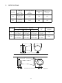
These air horns utilize stainless steel diaphragms and corrosion resistant castings
finished with a gray polyester coating. They are capable of being operated on air pressure of
20 to 150 p.s.i.g., but are tuned for optimum audibility at 80 to 90 p.s.i.g.
The Model 3H horn is tuned to a frequency of 750 Hz. It has a female 3/8 I.P.S threaded
opening for connection to the compressed air system, and is light enough to be supported by
the pipe to which it is connected.
The Model 6H horn is tuned to a frequency of 295Hz. It has a female 3/4 I.P.S. threaded
opening for connection to the compressed air system and is provided with a mounting ear
on top of the casting that includes two mounting holes for 1/2 inch bolts. It also contains a
mounting flange around the pipe opening with four mounting holes for 1/2 inch bolts.
B.
INSTALLATION.
1. Determine the location of the horn and air valve, and layout the airline to them from
the air source. For optimum performance the air line should be as short and as straight as
possible. Angles and bends should be avoided as much as possible, but where unavoidable,
it is recommended that long sweep elbows be used to maximize air flow to the horn.
NOTE
The valve to actuate the horn should be located as close to the horn as possible.
The farther it is located from the horn the longer it will take to obtain full volume
when activated and the longer it will take to stop sounding when deactivated.
2. Before attaching the horn to the air line, blow out the air line to remove any debris
that may have accumulated during assembly. Failure to do so may cause the debris to
become lodged in the air valve or between the horn diaphragm and body which will restrict
movement of the diaphragm and significantly affect horn performance.
3. It is recommended that a pipe union be used when connecting the horn and air
valve to the air line. This will allow for easier removal of the horn and air valve should service
be required.
-2-