1
I
GB
Nel ringraziarVi per la preferenza accordata a questo prodotto, la ditta è certa che
da esso otterrete le prestazioni necessarie al Vostro uso.
Leggete attentamente l’opuscolo ”Libretto istruzioni” che lo accompagna in quanto esso fornisce importanti indicazioni riguardanti la sicurezza, l’installazione, l’uso
e la manutenzione.
Questo prodotto risponde alle norme riconosciute della tecnica e delle disposizioni relative alla sicurezza.
Confermiamo che esso è conforme alle seguenti direttive europee: 89/336/CEE,
73/23/CEE (modificata da RL 91/263/CEE, 92/31/CEE e 93/68/CEE).
Thank you for buying this product, our company is sure that you will be more than
satisfied with the product’s performance.
The product is supplied an “INSTRUCTION MANUAL” which provides important
information about safety, installation, operation and maintenance.
This product complies with the recognised technical standards and safety regulations.
We declare that this product is in conformity with the following European Directives: 89/336/EEC and 73/23/EEC (amended by RL 91/263/EEC, 92/31/EEC and
93/68/EEC).
AVVERTENZE
Nelle operazioni di cablaggio ed installazione riferirsi alle
norme vigenti e comunque ai principi di buona tecnica.
IMPORTANT NOTE
For wiring and installation operations, refer to the
current standards and follow the main technical principles
ensuring good performance.
1) Generalità
ELMEC2 è adatta a controllare un motore trifase fino a 750 W di potenza.
La centralina è dotata di Dip-FIX che ne consentono la configurazione.
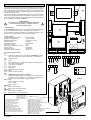
Le funzioni dei Dip-FIX vengono spiegate nei paragrafi seguenti e il collegamento
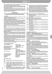
ai morsetti è illustrato dallo schema di figura 1.
2) Dati tecnici
Tensione di alimentazione trifase
Isolamento rete/bassa tensione
Rigidità dielettrica rete/bt
Corrente a vuoto
Alimentazione accessori
Corrente max relè
Potenza max assorbita dal motore
Finecorsa
Dimensione quadro
Temperatura di utilizzo
400V±10% 50Hz.
> 2MOhm 500Vdc
3750Vac per 1 minuto
0.05A max
24Vac 8VA max
1.6A
750W
contatto N.C.
183x225x120
-20/+55 °C
3) Collegamento morsettiera
JP1
1-2-3 Alimentazione trifase: 400V ±10% 50/60 Hz. Attenzione: prevedere il
sezionamento della linea a monte e 3 fusibili da 2A.
4-5-6 Collegamenti motore
JP3
7
Comune
7-8
Pulsante di STOP (N.C.). In caso di non utilizzo, lasciare ponticellato.
7-9
Finecorsa apertura (SWO)
7-10
Finecorsa chiusura (SWC)
9-11
Pulsante apertura
10-12 Pulsante chiusura
13-14 Uscita 24Vac 0.3A max (8VA)
JP4 (opzionale)
15-16 Antenna (15 segnale, 16 calza)
JP2
17-18 ATTENZIONE: Tensione di rete ai morsetti
Pulsante di EMERGENZA (N.C.). Utilizzare un pulsante di arresto con
ritenuta e con due contatti N.C. con almeno 8 mm di distanza in aria.
In caso di non utilizzo, lasciare ponticellato.
JP5 (opzionale)
Connettore ricevente 1-2 canali.
Canale 1 - Apre (opzionale)
Canale 2 - Chiude
DIP-FIX J1
ON
Comando chiusura automatica.
OFF
Comando chiusura ad uomo presente.
DIP-FIX J2
ON
Comando apertura automatica.
OFF
Comando apertura ad uomo presente.
2 - ELMEC2
1) General outline
The ELMEC2 control unit has been designed to control one three-phase motor
with a power up to 750 W.
The control unit is equipped with Dip-FIX which allow configuration of the unit.
The functions of the Dip-FIX are described in the following paragraphs while the
connection to the terminals is shown in the diagram of fig. 1.
2) Technical specifications
Three-phase main power supply
Mains insulation/low voltage
Dielectric strength/low voltage
No-load current
Power supply to accessories
Relay max current
Max power absorbed by motor
Limit switches
Control board dimensions
Working temperature
400V±10% 50Hz.
> 2MOhm 500Vdc
3750Vac per 1 minute
0.05A max
24Vac 8VA max
1.6A
750W
N.C. contact
183x225x120
-20/+55 °C
3) Terminal board connection
JP1
1-2-3 Three-phase power supply: 400V ±10% 50/60 Hz. WARNING: break the
line upstream and fit three 2A fuses.
4-5-6 Motor connections
JP3
7
Common wire
7-8
STOP push button (N.C.). If not used, leave jumped.
7-9
Opening limit switch (SWO)
7-10
Closing limit switch (SWC)
9-11
Opening push button
10-12 Closing push button
13-14 Output 24Vac 0.3A max (8VA)
JP4 (on request)
15-16 Antenna (15 signal, 16 braid)
JP2
17-18 WARNING: Mains current to terminals
EMERGENCY push button (N.C.). Use a stop hold-to-run push button
and two N.C. contacts having at least 8 mm air distance. If not used,
leave jumped.
JP5 (on request).
1-2 channel receiver connector.
Channel 1 - Opens
Channel 2 - Closes
DIP-FIX J1
ON
Automatic closing control.
OFF
Hold-to-run closing control.
DIP-FIX J2
ON
Automatic opening control.
OFF
Hold-to-run opening control.