1
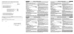
INSTALLATION MANUAL 1) GENERAL OUTLINE BTBAT mod. buffer battery kit. Allows the automation system to operate even when the mains power supply is disconnected for a short time. The pack is made up of: • 2 battery back up units (ref. B). • 1 battery charger board (ref. SBS). • 1 battery fixing bracket • Connection cables, spacers, screws. • Fitting instruction manual. Note: The BT BAT kit is also available already assembled and prewired on a SD box, to be used for all the LIBRA boards and the HYDRA boards fitted inside the operator (Fig. 3). 2) SBS BOARD AND BATTERY SPECIFICATIONS Charge voltage: .......................................... 27.2Vdc Charge current: ............................................. 130mA Data detected with external temperature of: ... 25°C Battery capacity: .............................. 2x (12V 1.2Ah) Exhausted battery protection threshold: .... 20.4Vdc Battery recharging time: .............................. 12/14 h 3) FITTING All the fitting and connection operations must be carried out by qualified personnel. To fit this accessory, proceed as specified below. BT BAT to be fitted to a Hydra QSG control panel - Disconnect the power supply. - Fix the board in the position shown in Fig. 4, using appropriate spacers “D” supplied as standard. - Then fix the batteries, using the appropriate bracket as shown in Fig. 4. - Carry out connections as shown in the diagram in Fig, 1 for the LIBRA control panel and diagram in Fig. 2 for HYDRA panel. BT BAT preinstalled on SD box - Disconnect the power supply. - Carry out connections as shown in the diagram in Fig, 1 for the LIBRA control panel and diagram in Fig. 2 for HYDRA panel IMPORTANT NOTE: In the panels supplied by battery back up power, the “24Va.c.” and “Vsafe 24Va.c.” outputs have a 24Vd.c. voltage, polarised as shown in Fig. 1 for the LIBRA board and in Fig. 2 for the HYDRA board. At the time of installing the BT-BAT kit, check that the devices supplied by these outputs are correctly connected. 4 - BT BAT - Ver. 02 4) BATTERY REMOVAL When removing the batteries, observe the current regulations and in particular: 1) Remove the batteries before dismantling the operator. 2) The batteries must be discarded safely. 3) The appliance must be disconnected from the power supply during battery removal. Having disconnected the power supply. remove the wiring existing between the batteries and the SBS board. Then, remove the fixing bracket S and dispose of the batteries according to whatever prescribed by the current regulations. The descriptions and illustrations contained in the present manual are not binding. The Company reserves the right to make any alterations deemed appropriate for the technical, manufacturing and commercial improvement of the product, whileleaving the essential product features unchanged, at any time and without undertaking to update the present publication. D811336_02 ENGLISH