1
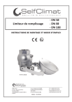
Limiteur de remplissage - DN 50 NT - DN 80 NT - DN 80 INOX INSTRUCTIONS DE MONTAGE ET MODE D’EMPLOI NF EN 13616 Siège social : Z.I Sud - Rue des Epinettes CS 50152 TORCY 77208 MARNE LA VALLEE CEDEX 1 FRANCE S.A. au Capital de 315 000€ N°SIREN 698 202 868 00023 NAF 4674B N°TVA FR 25 698 202 868 Edition : 01/2014 Tél : +33(0)1 60 05 18 53 Fax : +33(0)1 60 17 58 39 [email protected] www.selfclimat-morvan.com AVERTISSEMENT ! CE MANUEL DOIT ÊTRE LU AVEC ATTENTION PAR TOUTES LES PERSONNES QUI ONT OU QUI AURONT LA RESPONSABILITE DE L’INSTALLATION OU DE L’UTILISATION DU PRODUIT. MISE EN GARDE ! Pour des raisons de sécurité, cet appareil doit être utilisé par du personnel HABILITE A TRAVAILLER SUR DU MATERIEL UTILISABLE DANS DES ATMOSPHERES EXPLOSIBLES. Veuillez lire et prendre pleine connaissance de ce manuel avant utilisation. IMarquage TABLE DES MATIERES 3 II Caractéristiques générales 2.1 Description 2.2 Liste non exhaustive des produits chimiques pouvant être utilisés avec les LDR DN 50 NT et DN 80 NT 3 3 4 III IV Instructions d’utilisation 3.1 Consignes de sécurité 3.2 Mise en service 3.3 Fonctionnement 4 4 4 4 Montage 4.1 Installation du limiteur de remplissage 4.2 Entretien et dépannage 4.3 Démontage 6 6 7 7 V Conditions particulières 7 VI Accessoires en option 7 VII Données techniques 8 VIII Normes et agréments 9 FOURNITURES A réception du colis, veuillez vous assurer de l’emballage d’origine et du bon état du matériel. La fourniture doit comprendre : - le limiteur de remplissage Self Climat - la plaque signalétique avec deux clous sous pochette - le manuel d’instructions - la déclaration de conformité 2 I) MARQUAGE Les matériaux de type limiteur de remplissage Self Climat DN 50 NT, DN 80 NT et DN 80 INOX sont conformes à la directive 94/9/CE. Le matériel utilisable dans les atmosphères explosibles du groupe IIB est construit conformément aux normes harmonisées suivantes : NF EN 13616 : 2004 - catégorie A2 - étanchéité vapeur : non NF EN 13463-5 : 2003 NF EN 13463-1 : 2001 (La conformité matérielle n’est pas impacté par les modifications substantielles de la norme NF EN 13463-1 : 2009) DN 50 NT Self Climat 77200 TORCY FRANCE Limiteur de Remplissage Type DN50 NT Sous-Catégorie A2 0080 II1 G c IIB T6 T amb. : -25°C à +60°C INERIS 07ATEX0037 DN 80 NT DN 80 INOX Self Climat 77200 TORCY FRANCE Limiteur de Remplissage Type DN80 NT Sous-Catégorie A2 0080 II1 G c IIB T6 T amb. : -25°C à +60°C INERIS 07ATEX0037 Self Climat 77200 TORCY FRANCE Limiteur de Remplissage Type DN80 INOX Sous-Catégorie A2 0080 II1 G c IIB T6 T amb. : -25°C à +60°C INERIS 07ATEX0037 II) CARACTERISTIQUES GENERALES 2.1 / Description Le limiteur de remplissage Self Climat est un appareil de sécurité mécanique placé sur le tube de remplissage à l’intérieur du réservoir de stockage de liquide. Cet appareil «Dispositif anti-débordement à sécurité totale» a pour objet de réduire les risques pour l’environnement, les risques de pollution de l’eau ainsi que tout risque d’incendie ou d’explosion susceptibles de se produire lors du remplissage de réservoirs de stockage de produits industriels ou chimiques. Avant son installation, il est obligatoire de s’assurer de la compatibilité entre le limiteur de remplissage et la nature de liquide stocké à l’intérieur du réservoir, les caractéristiques du liquide déterminant le type de limiteur de remplissage à installer. Pour cela, le Service Technique Self Climat possède les connaissances requises pour conseiller l’installateur dans son choix. LIMITEUR DE REMPLISSAGE Désignation LDR - Type DN 50 NT LDR - Type DN 80 NT LDR - Type DN 80 INOX Débit DN Pression Référence pompe d’utilisation Température * d’utilisation Température Max. Fluide 6 bar 8 bar 8 bar -25°C à +60°C -25°C à +60°C -25°C à +60°C +80°C +80°C +80°C 40 m3/h 50 60 m3/h 80 60 m3/h 80 308 279 308 277 308 268 * La température du matériel dépend de la température du fluide 3 2.2 / Liste non exhaustive des produits chimiques pouvant être utilisés avec les LDR DN 50 NT et DN 80 NT 1 - acétate d’isopropyle 2 - acétate d’éthyle 3 - acétate butyle 4 - acétate d’éthyl glycol 5 - acétone 6 - acide rosolique 7 - acide hexavanadique 8 - acide acétique 9 - alcool à brûler 10 - alcool dénaturé 95° 11 - alcool 90° 12 - alcool méthylique 13 - alcool éthylique 14 - alcool isopropylique 15 - alcool isibutylique 16 - alcool butylique normal 17 - anthracène 18 - antigel 19 - benzine 20 - benzol 21 - black warnish 22 - butanol 23 - buthyglycol 24 25 26 27 28 29 30 31 32 33 34 35 36 37 38 39 40 41 42 43 44 45 46 - carbonyl foncé carbonyl clair chlorure de benzol coaltar diéthylène glycol dioctyle phalate dilutine M5 diluant réf.7031 dutrex réf. 238 FC essence A essence C essence E essence F essence 92/98 essence de térébenthine essences diverses essence de mirbane éthyle glycol exsol 140/170 glycol glycérine hexane héxylène glycol 47 48 49 50 51 52 53 54 55 56 57 58 59 60 61 62 63 64 65 66 67 68 69 - huile anti-poussière huile AD claire huile A1 huile de lin ROB 108 huile de goudron huile minérale huiles végétales huile réf. P223 IPA 91 IPA 99 iso propanol méthyl éthyl cétone méthyl isobuthyl cétone méthyl glycol méthanol monopropylène glycol monoéthylène glycol M.E.K. M.I.B.K. naphta pentane perchloréthylène pétrole lampant 70 71 72 73 74 75 76 77 78 79 80 81 82 83 84 85 86 87 88 89 90 91 92 - pétrole désodorisé propanol solvesso 150 (white) shell sol A shell sol E shell sol K shell sol R shell sol T solvants régénérés solvants usés solvant naphta 90/170 solvant naphta 90/160 S3 dilluant/solvant lourd total S6 dilluant/solvant lourd total sulfure de carbone toluène télura réf.168 trichloréthylène tétrachlorure de carbone varsol white spirit B.T.A. white spirit ordinaire xylène III) INSTRUCTIONS D’UTILISATION 3.1 / Consignes de securité Toute modification de l’appareil peut invalider la certification de celui-ci. Consulter les certificats ainsi que les documents relatifs aux équipements de l’appareil afin de s’informer de la classe de température et du groupe d’explosion. L’intervenant doit être habilité pour les interventions ATEX afin d’éviter la dégradation du mode de protection des équipements certifiés. 3.2 / Mise en service L’installation et les raccordements ne peuvent être effectués que par du personnel qualifié. Les normes EN correspondantes et les règlementations nationales en matière de sécurité des appareils, de même que les règles générales admises dans le domaine technique doivent impérativement être respectées. 3.3 / Fonctionnement Introduction Le limiteur de remplissage Self Climat permet le remplissage du réservoir qu’il équipe jusqu’à un niveau de fermeture N1. A cette fermeture un écoulement résiduel de liquide resté en amont de l’appareil est autorisé une fois ce niveau atteint et la procédure de remplissage est arrêtée. Le Limiteur de Remplissage Self Climat peut équiper indépendamment les installations de remplissage par gravité ou par groupe de pompage. 4 Fonctionnement détaillé Principe de fonctionnement du LDR Self Climat tYPE nt ET inox 1) lIMITEUR DE REMPLISSAGE EN POSITION REPOS - Le flotteur est en position basse. - Le piston en position haute (ouverture totale). - Les lumières d’écoulement sont totalement dégagées. 2) PROCESSUS DE FERMETURE AVANT LE NIVEAU N1 - La montée progressive du niveau à l’intérieur de la cuve entraîne l’élévation du flotteur. - Celui-ci actionne la fermeture progressive du piston - Le piston obstrue partiellement les lumières d’écoulement. - Le flotteur poursuit sa montée. - Les lumières d’écoulement sont fermées. - La pression hydraulique croissante entraîne la fermeture totale du piston. 3) A CET INSTANT LE NIVEAU N1 EST ATTEINT : LE LIMITEUR ASSURE UNE FERMETURE TOTALE - Le piston obstrue totalement les lumières d’écoulement. - Le flotteur est en position haute. 4) PROCEDER A LA FERMETURE DE LA VANNE CAMION ET A LA PRISE D’AIR ADDITIONNELLE 5) VOLUME RESIDUEL Après avoir procédé à la fermeture de la vanne camion et à la prise d’air additionnelle, la pression résiduelle exercée sur le piston s’élimine à ce moment : - Le flotteur est maintenu immergé. - Le piston remonte partiellement. - Les lumières d’écoulement sont partiellement ouvertes. Cette ouverture partielle des lumières d’écoulement permet un écoulement résiduel de liquide resté éventuellement en amont de l’appareil. Il est possible de calculer le volume résiduel admis sachant que la différence de hauteur autorisée correspond environ à 20 mm après le niveau N1. Plateau du réservoir 50 mm Soupape de décharge (Type NT) NIVEAU N1 Flotteur Repos 5 IV) MONTAGE 4.1 / Installation du limiteur de remplissage IMPORTANT : Pendant le montage, protégez le limiteur contre les impuretés telles que le sable 1 : Il est recommandé de positionner le Limiteur dans l’axe longitudinal du réservoir. 2 : Monter le Limiteur de Remplissage sur la douille du tuyau sous le plateau de trou d’homme. La côte de 50 mm minimum entre le dessus du limiteur et le générateur du réser voir doit absolument être respectée. (Figure 2) 3 : Raccorder le tuyau (position 2/Figure 1) au limiteur : - mesurer la distance X entre la bague du trou d’homme et le fond du réservoir - racourcir le tuyau de façon à laisser 70 mm d’espace entre le dessous du tuyau et le fond du réservoir. 4 : Afin de respecter la mise à la terre du limiteur de remplissage lors de son montage dans la cuve, il convient de s’assurer de l’équipotentialité entre la douille du tuyau du trou d’homme et le tuyau situé en partie basse du limiteur. 5 : Remettre le couvercle de trou d’homme après montage de la conduite de remplissage et vérifier si le flotteur ne frotte pas contre les tuyaux internes. 6 : Vérifier le diamètre de l’évent du réservoir dont la section doit être au moins égale au quart de la section de la tuyauterie de remplissage (Art.9 Arrêté du 22 juin 1998 relatif aux réservoirs enterrés de liquides inflammables). 7 : Monter la plaque d’identification sur la conduite de remplissage. Plateau du réservoir Soupape de décharge (Type NT) 50 mm NIVEAU N1 X X - 70 1 Flotteur Repos 2 Figure 1 Attention : Ne pas mettre en pression la cuve avec un limiteur de remplissage. 6 Figure 2 4.2 / Entretien et dépannage Les opérations pouvant être effectuées par l’utilisateur se limitent à l’installation et aux raccordements. Toute intervention de démontage, réparation ou modification sur le limiteur de remplissage annule systématiquement la garantie constructeur. Par conséquent, toute intervention ne peut être effectuée que par la société «Self Climat» après retour de l’appareil d’origine à l’usine. En cas de défaillance du limiteur de remplissage, celui-ci sera à retourner à : Self Climat Z.I Sud - Rue des Epinettes CS 50152 TORCY 77208 MARNE LA VALLEE CEDEX 1 FRANCE Un test de continuité électrique doit être effectué tous les ans. Ce test ne peut être effectué que par du personnel habilité à travailler sur du matériel utilisable dans les atmosphères explosibles. 4.3 / Démontage Le Limiteur de Remplissage ne peut être démonté qu’en cas de dysfonctionnement ou de remplacement de celui-ci. Il ne peut être démonté que par du personnel habilité à travailler sur du matériel utilisable dans les atmosphères explosibles. V) CONDITIONS PARTICULIERES Les limiteurs de remplissage automatiques Self Climat sont garantis un an contre tout vice de fabrication reconnu par notre usine à dater du jour de facturation. Nos limiteurs ne peuvent en aucun cas subir de modifications quelles qu’elles soient, sans entraîner la perte de la garantie. N’étant pas installé par nos soins, il ne peut être prétendu à quelque indemnité que ce soit pour cause directe et indirecte. VI) ACCESSOIRES EN OPTION Perspective 1 1) Le testeur Réf : 308 267 +/- 180 Piquage 1" Soupape de décharge (Type NT) Composition - Câble inox ø 1mm Lg 2 m à une extrémité un anneau de traction, à l’autre extrémité un serre câble. - Raccord laiton ø 1’’ F équipé d’un couvercle à chaînette. LDR Self Climat NT/INOX Testeur en position de repos - monté sur LDR NT/INOX 7 Méthode de test Perspective 2 Moyen de vérification manuelle du bon foctionnement du limiteur. A l’aide de l’anneau, exercer progressivement une traction sur le câble afin d’amener le flotteur en position haute. Faire redescendre lentement le flotteur à sa position de repos. Recommencer cette manoeuvre plusieurs fois pour s’assurer qu’aucun obstacle ne s’oppose au libre mouvement du flotteur sur toute sa trajectoire. +/- 180 Piquage 1" LDR Self Climat NT/INOX Soupape de décharge (Type NT) Testeur en position d’essai - monté sur LDR NT/INOX Il est impératif de veiller à ce que l’orifice du testeur soit toujours placé sur le plateau de trou d’homme et non pas sur le corps du réservoir. Procédure Lorsque le testeur est installé, il est obligatoire de vérifier son bon fonctionnement avant tout premier remplissage de la cuve selon le procédé décrit dans Méthode de test. Ceci permet de valider la bonne installation du LDR. Une fois le testeur installé, il est obligatoire de procéder à cette vérification au moins une fois par an. 2) Collier de support 8 Désignation Référence Collier de support 50/60 Collier de support 80/90 308 242 308 243 VII) DONNEES TECHNIQUES Code produit Côte A (mm) B (mm) C (mm) Construction Corps Flotteur Visserie et autres pièces Fonctionnement Raccordement Pression Max. Débit Min. Débit Max. Taux de viscosité Max. Température Type de dépotage Poids 308 279 Type DN 50 NT ø50/60 159 295 Type DN 50 NT 308 277 Type DN 80 NT 308 268 Type DN 80 Inox Type DN 80 NT Type DN 80 Inox Type DN 80 NT Type DN 80 Inox ø80/90 207 400 Aluminium anodisé Inox Inox Aluminium anodisé Inox Inox 2" F/F GAZ 6 bar 1,4 m3/h 40 m3/h 55 cSt -25°C à +60°C Pompe ou gravité 2,50 kg 3" F/F GAZ 8 bar 3,6 m3/h 60 m3/h 55 cSt -25°C à +60°C Pompe ou gravité 5,00 kg Type DN 50 NT ø80/90 207 400 Inox Inox Inox 3" F/F GAZ 8 bar 3,6 m3/h 60 m3/h 55 cSt -25°C à +60°C Pompe ou gravité 9,80 kg 9 VIII) NORMES ET AGREMENTS Le limiteur de remplissage Self Climat subit des tests et essais de fonctionnement réguliers afin de garantir la qualité du produit et d’obtenir des nouveaux certificats de conformité. A ce jour le Limiteur de remplissage est conforme aux normes suivantes: Désignation LDR Type DN 50 NT LDR Type DN 80 NT LDR Type DN 80 INOX Référence Europe Pays - Bas Belgique 308 279 308 277 308 268 EN 13616 EN 13616 EN 13616 KIWA BRL - K 636 KIWA BRL - K 636 KIWA BRL - K 636 Vlarem II Vlarem II Vlarem II Le système Self Climat pouvant fonctionner indépendamment par gravité ou par groupe de pompage, son utilisation est aujourd’hui préconisé dans la plupart des pays d’Europe et du monde entier. Number Issued Product Certificate Replaces Dated Overfill prevention devices for storage tanks for liquid petroleum fuels Kiwa N.V. Sir W. Churchill-laan 273 P.O. Box 70 2280 AB RIJSWIJK ZH The Netherlands Tel. +31 70 414 44 00 Fax +31 70 414 44 20 E-mail [email protected] www.kiwa.nl Siège social : Z.I Sud - Rue des Epinettes CS 50152 TORCY 77208 MARNE LA VALLEE CEDEX 1 FRANCE 10 Company Representative S.A. au Capital de 315 000€ N°SIREN 698 202 868 00023 NAF 4674B N°TVA FR 25 698 202 868 Tél : +33(0)1 60 05 18 53 Fax : +33(0)1 60 17 58 39 [email protected] www.selfclimat-morvan.com WARNING ! THIS MANUAL SHOULD BE READ CAREFULLY BY ALL PERSONS WHO ARE OR WILL BE RESPONSIBLE FOR THE INSTALLATION OR OPERATION OF THE PRODUCT. CAUTION ! FOR SAFETY REASONS,THIS DEVICE SHOULD BE USED BY PERSONNEL AUTHORISED TO WORK ON EQUIPMENT FOR USE IN EXPLOSIVE ATMOSPEHERES. PLEASE READ AND DIGEST THIS MANUAL BEFORE USING THE APPLIANCE. CONTENTS I Marking II General specifications 2.1Descritpion 2.2 Non-exhaustive list of chemicals that can be used with DN 50 NT and DN 80 NT overfill prevetion devices III IV Operating instructions 3.1 Safety instructions 3.2 Starting up 3.3 Operation V Special conditions VI Optional accessories VII Technical data Vii Standards and approvals 11 11 11 12 12 12 12 12 Fitting 4.1 Installating the overfill prevention device 4.2 Maintenance and trouble shooting 4.3 Dismantling 14 14 15 15 15 15 16 17 SUPPLIES On receipt of the delivery, check that the packaging is original and that the equipment is in good condition. The supply should comprise : - The Self Climat overfill prevention device - The manufacturer’s plate and two nails in a sachet - The instruction manual - The declaration of conformity 11 I) MARKING Self Climat DN 50 NT, DN 80 NT and DN 80 Inox type overfill prevention devices all conform to the 94/9/EC directive. This equipment, suitable for use in group IIB explosive atmospheres, is constructed according to the following European standards : NF EN 13616 : 2004 NF EN 13463-1 : 2001 NF EN 13463-5 : 2003 DN 50 NT Self Climat 77200TORCY FRANCE Limiteur de Remplissage Type DN50 NT Subtype A2 0080 II1 G c IIB T6 T amb. : -25°C à +60°C INERIS 07ATEX0037 DN 80 NT DN 80 INOX Self Climat 77200TORCY FRANCE Limiteur de Remplissage Type DN80 NT Subtype A2 0080 II1 G c IIB T6 T amb. : -25°C à +60°C INERIS 07ATEX0037 Self Climat 77200TORCY FRANCE Limiteur de Remplissage Type DN80 INOX Subtype A2 0080 II1 G c IIB T6 T amb. : -25°C à +60°C INERIS 07ATEX0037 II) GENERAL SPECIFICATIONS 2.1 / Description The Self Climat overfill prevention device is a mechanical safety device placed on the filling tube inside the liquid storage tank. The purpose of this «completely safe overflow prevention device» is to reduce environmental risks, water pollution risks and all fire or explosion risks that could arise while filling liquid petroleum fuel storage tanks. It is essential to verify the compatibility between the overfill prevention device and the liquid stored in the tank, as the characteristics of the liquid determine the type of overfill prevention device to be installed. The Self Climat technical dept has all the information necessary to advise installing technicians in their choices. OVERFILL PREVENTION DEVICE Description OPD- DN 50 NT Type OPD - DN 80 NT Type OPD - DN 80 INOX Type Pump flow DN 40 m3/h 50 60 m3/h 80 60 m3/h 80 Working pressure Reference Working temperature* Max. fluid temperature 6 bars 8 bars 8 bars 308 279 308 277 308 268 -25°C to +60°C -25°C to +60°C -25°C to +60°C +80°C +80°C +80°C * The temperature of the equipment depends on the temperature of the fluid 12 2.2 / Non exhaustive list of chemicals that can be used with DN 50 NT and DN 80 NT overfill prevention devices 1 - isopropyl acetate 2 - ethyl acetate 3 - butyl acetate 4 - ethyl glycol acetate 5 - acetone 6 - rosolic acid 7 - hexavanadic acid 8 - acetic acid 9 - methylated spirit 10 - denatured alcohol 95° 11 - alcohol 90° 12 - methyl alcohol 13 - ethyl alcohol 14 - isopropyl alcohol 15 - isobutyl alcohol 16 - normal isobutyl alcohol 17 - anthracene 18 - antifreeze 19 - benzine 20 - benzole 21 - black warnish 22 - butyl alcohol 23 - buthyl glycol 24 25 26 27 28 29 30 31 32 33 34 35 36 37 38 39 40 41 42 43 44 45 46 - dark carbonyl light carbonyl benzole chloride coal tar dihydroxydiethyl ether dioctyle phalate dilutine M5 thinner réf.7031 dutrex réf. 238 FC gasoline A gasoline C gasoline E gasoline F gasoline 92/98 turpentine miscellaneous spirits nitrobenzine ethyl glycol exsol 140/170 glycol glycerine hexane hexylene glycol 47 48 49 50 51 52 53 54 55 56 57 58 59 60 61 62 63 64 65 66 67 68 69 - dust-laying oil clear AD oil oil A1 linseed oil ROB 108 tar oil mineral oil vegetable oils oil réf. P223 IPA 91 IPA 99 isopropyl alcohol methyl ethyl ketone methyl isobutyl ketone methyl glycol methanol monopropylene glycol monoethylene glycol M.E.K. M.I.B.K. naphta pentane tetrachlorethylene lamp oil 70 71 72 73 74 75 76 77 78 79 80 81 82 83 84 85 86 87 88 89 90 91 92 - deodorised naphta propyl alcohol solvesso 150 (white) shellsol A shellsol E shellsol K shellsol R shellsol T regenerated solvents dirty solvents naphta 90/170 solvent naphta 90/160 solvent S3 total heavy solvent S6 total heavy solvent carbon disulphide toluene telura réf.168 trichlorethylene carbon tetrachloride varsol white spirit B.T.A. ordinary white spirit xylene III) OPERATING INSTRUCTIONS 3.1 / Safety instructions Any modification to the appliance may invalidate its certification. Consult the cerficates and the documents relative to the fittings to the appliance in order to check on the temperature class and explosion group. The person doing the work should be authorised for ATEX work to prevent the deterioration of the mode of protection of the equipment certified. 3.2 / Starting up Installation and connection can only be done by qualified personnel. The corresponding EN standards and national regulations covering the safety of appliances, as well as general rules accepted in technical field, must be followed. 3.3 / Operation Introduction The Self Climat overfill prevention device allows the tank it is fitted to, to be filled to closing level L1. At this closure a residual flow of liquid upstream of the appliances is authorised once the level is reached and the filling procedure has stopped. The Self Climat overfill prevention device can equip gravity filled or pumped installations. 13 Detailed operation OPERATING PRINCIPLE OF THE Self Climat nt AND STAINLESS STEEL OVERFILL PREVENTION DEVICES 1) OVERFILL PREVENTION DEVICE IN THE REST POSITION - The float is in the bottom position. - The piston is in the top position (fully open). - The drain ports are completely open. 2) THE CLOSING PROCESS BEFORE THE L1 LEVEL - The progressive rise in the level inside the tank causes the float to rise - This causes the progressive closure of the piston - This piston partially closes the drain ports. - The float continues to rise. - The drain ports are closed. - The increasing hydraulic pressure causes the complete closure of the piston. 3) AT THIS POINT THE LEVEL IS REACHED: THE OVERFILL PREVENTION DEVICE IS FULLY CLOSED - The piston totally closes the drain ports. - The float is in the top position. 4) CLOSE THE LORRY VALVE AND PROCEED TO THE ADDITIONAL AIR INLET 5) RESIDUAL VOLUME After closing the lorry valve and proceeding to the additional air inlet, the residual pressure on the piston is cancelled out. At this moment : - The float is kept submerged. - The piston rises partially. - The drain ports are partially open. This partial opening of the drain ports allows any residual liquid upstream of the appliance to flow out. It is possible to calculate the residual volume accepted, bearing in mind that the difference in height allowed is approximately 20 mm after level L1. Top of manhole 50 mm Release valve (Type NT) LEVEL L1 Float Rest position 14 IV) FITTING 4.1 / Installating the overfill prevention device IMPORTANT : Protect the overfill prevention device against impurities such as sand during fitting. 1 : We recommend positioning the overfill prevention device on the longitudinal axis of the tank. 2 : Mount the overfill prevention device on the pipe sleeve under the manhole plate. The 50mm minimum distance between the top of the overfill prevention device and the tank generator must be respected in all circumstances. (Figure 2) 3 : Connect the pipe (postion 2/Figure 1) to the ball valve : - measure distance X between the manhole ring and the tank bottom. - shorten the pipe to leave a space of 70 mm between the bottom of the pipe and the tank bottom. 4 : To confirm the earthing of the overfill prevention device when fitting it in the tank, check that the potentials of the manhole pipe sleeve and the pipe situated at the bottom of the overfill prevention device are the same. 5 : Replace the manhole plate after fitting the filler pipe and check that the float cannot rub against the internal pipes. 6 : Check the diameter of the tank vent. Its cross-section should be at least equal to a quarter of the crosssection of the filler pipe. 7 : Fit the manufacturer’s plate in the filler pipe. Top of manhole Release valve (Type NT) 50 mm LEVEL L1 X - 70 X 1 Float Rest position 2 Figure 1 Figure 2 Caution: Do not make any pressure test of tank with overfill prevention device installaed. 15 4.2 / Maintenance and trouble shooting The operations that can be done by user are limited to installation and connecting up. Any dismantling, repair or modification to the overfill prevention device automatically cancels the manufacturer’s warranty. Consequently, this work can only be done by the «Self Climat» company after return of the appliance to the factory. In the event of a fault on the overfill prevention device it should be returned to : Self Climat Z.I Sud - Rue des Epinettes CS 50152 TORCY 77208 MARNE LA VALLEE CEDEX 1 FRANCE An electrical continuity test must be done every year. This test can only be done by personnel authorised to work on equipment for use in explosive atmospheres. 4.3 / Dismantling The overfill prevention device can only be dismantled in the event of malfunctioning or replacement. It can only be dismantled by personnel authorised to work on equipment for use in explosive atmospheres. V) SPECIAL CONDITIONS Self Climat automatic overfill prevention devices are guaranteed for one year from the invoice date against manufacturing faults accepted by our factory. Our overfill prevention devices cannot be modified in any way without causing a loss warranty. As we do not install the equipment ourselves no claim whatsoever for indemnity will be accepted whether for direct or indirect causes. VI) OPTIONAL ACCESSORIES Perspective 1 1) Tester Ref : 308 267 +/- 180 Composition - Stainless steel cable ø 1mm Lg 2 m At one end a traction ring and at the other a cable clamp - Brass union ø 1’’ F, fitted with a cover on a chain. 16 Release valve (Type NT) 1" tapping Self Climat OPD NT/INOX Tester in the rest position - fitted on the float NT/INOX Test method Perspective 2 A means of manually testing the correct operation of the float valve. Pull the cable progressively, using the ring, to bring the float to its top position. Lower the float slowly to its rest position. Repeat this operation several times to make sure that nothing prevents the float moving freely throughout its travel. +/- 180 1"Tapping Self Climat OPD NT/INOX Release valve (Type NT) Tester in the test position - fitted on the float NT/INOX It is essential to ensure that the tester orifice is always on the manhole plate and not on the tank. Procedure When the tester is installed, it is essential to check its operation according to the procedure described in Test Method before filling the tank for the first time. This enables the correct installation of the overfill prevention device to be confirmed. Once the tester is installed, this check must be performed at least once a year. 2) Support clamp Description Reference Support clamp 50/60 Support clamp 80/90 308 242 308 243 17 VII) TECHNICAL DATA Reference Dimension A (mm) B (mm) C (mm) Construction Body Float Fastenings and other parts Operating Connection Max. Pressure Min. Flow Max. Flow Max. Viscosity rating Temperature Type of transfer Weight 18 308 279 DN 50 NT Type ø50/60 159 295 DN 50 NT Type 308 277 DN 80 NT Type 308 268 DN 80 Inox Type DN 80 NT Type DN 80 Inox Type DN 80 NT Type DN 80 Inox Type ø80/90 207 400 Anodised Aluminium Stainless steel Stainless steel Anodised Aluminium Stainless steel Stainless steel 2" F/F GAZ 6 bar 1,4 m3/h 40 m3/h 55 cSt -25°C à +60°C Pump or gravity 2,50 kg 3" F/F GAZ 8 bar 3,6 m3/h 60 m3/h 55 cSt -25°C à +60°C Pump or gravity 5,00 kg DN 50 NT Type ø80/90 207 400 Stainless steel Stainless steel Stainless steel 3" F/F GAZ 8 bar 3,6 m3/h 60 m3/h 55 cSt -25°C à +60°C Pump or gravity 9,80 kg VIII) STANDARDS AND APPROVALS The Self Climat overfill prevention device is subject to regular operating tests in order to guarantee the quality of the product and obtain new certifcates of conformity. To date the overfill prevention device conforms to the following standards : Descritption DN 50 NT Type OPD DN 80 NT Type OPD DN 80 INOX Type OPD Reference Europe The Netherlands Belgium 308 279 308 277 308 268 EN 13616 EN 13616 EN 13616 KIWA BRL - K 636 KIWA BRL - K 636 KIWA BRL - K 636 Vlarem II Vlarem II Vlarem II As the Self Climat system can operate by gravity and with pumps, its use is now recommended in most countries in Europe and worldwide. Number Issued Product Certificate Replaces Dated Overfill prevention devices for storage tanks for liquid petroleum fuels Kiwa N.V. Sir W. Churchill-laan 273 P.O. Box 70 2280 AB RIJSWIJK ZH The Netherlands Tel. +31 70 414 44 00 Fax +31 70 414 44 20 E-mail [email protected] www.kiwa.nl Head office : Z.I Sud - Rue des Epinettes CS 50152 TORCY 77208 MARNE LA VALLEE CEDEX 1 FRANCE Company Representative SA with Capital of €315,000 SIREN registration no.698 202 868 00023 NAF Code 4674B VAT No. FR 25 698 202 868 Tel : +33(0)1 60 05 18 53 Fax : +33(0)1 60 17 58 39 [email protected] www.selfclimat-morvan.com 19 WAARSCHUWING ! DEZE HANDLEIDING MOET AANDACHTIG GELEZEN WORDEN DOOR IEDEREEN DIE VERANTWOORDELIJK IS OF ZAL ZIJN VOOR DE INSTALLATIE OF HET GEBRUIK VAN HET PRODUCT. OPGELET ! UIT VEILIGHEIDSOVERWEGINGEN MOET DIT TOESTEL GEBRUIKT WORDEN DOOR PERSONEN DIE BEVOEGD ZIJN OM TE WERKEN MET MATERIAAL DAT GEBRUIKT MAG WORDEN IN OMGEVINGEN WAAR ONTPLOFFINGSGEVAAR KAN HEERSEN. GELIEVE VOOR GEBRUIKT DEZE HANDLEIDING VOLLEDIG TE LEZEN. INHOUDSOPGAVE I Markering II Algemene kenmerken 2.1 Omschrijving 2.2 Niet-volledige lijst van chemische producten die gebruikt kunnen worden met de overvulbeveiligingen DN 50 NT en DN 80 NT 19 19 20 III IV Gebruiksinstructies 3.1 Veiligheidsrichtlijnen 3.2 Inbedrijfstelling 3.3 Werking 20 20 20 20 Montage 4.1 Installatie van de overvulbeveiliging 4.2 Onderhoud en reparatie 4.3 Demontage 22 23 23 23 V Bijzondere voorwaarden 23 VI Optioneel toebehoren 23 VII Technische gegevens 24 Viii Normen en goedjeuringen 19 25 LEVERINGEN Bij ontvangst van het collo, gelieve te controleren of het in de originele verpakking zit en of het materiaal in goede staat is. De levering moet het volgende omvatten : - De Self Climat overvulbeveiliging - Het constructeurplaatje met twee klinknagels in mapje - De instructiehandleiding - De verklaring von conformiteit 20 I) MARKERING Apparatuur zoals de Self Climat overvulbeveiliging DN 50 NT, DN 80 INOX en DN 80 INOX is in overeenstemming met richtlijn 94/9/EG. Het materiaal dat gebruikt mag worden in omgevingen waar ontploffingsgevaar kan heersen uit groep IIB is vervaardigd in overeenstemming met de volgende Europese normen : : 2004 NF EN 13616 NF EN 13463-1 : 2001 NF EN 13463-5 : 2003 DN 50 NT DN 80 NT Self Climat 77200TORCY FRANCE Overvulbeveiliging Type DN50 NT Subtype A2 0080 II1 G c IIB T6 T amb. : -25°C à +60°C INERIS 07ATEX0037 Self Climat 77200TORCY FRANCE Overvulbeveiliging Type DN80 NT Subtype A2 0080 II1 G c IIB T6 T amb. : -25°C à +60°C INERIS 07ATEX0037 DN 80 INOX Self Climat 77200TORCY FRANCE Overvulbeveiliging Type DN80 INOX Subtype A2 0080 II1 G c IIB T6 T amb. : -25°C à +60°C INERIS 07ATEX0037 II) ALGEMENE KENMERKEN 2.1 / Omschrijving De Self Climat overvulbeveiliging is een mechanische veiligheidsvoorziening die op de vulbuis in het vloeistofreservoir geplaatst wordt. Dit toestel «Overvulbeveilingssysteem met totale veiligheid» moet de risico’s voor het milieu, de risico’s van waterverontreiniging en het brand - of ontploffingsgevaar beperken, die kunnen voorkomen tijdens het vullen van opslagreservoirs van vloeibare minerale brandstoffen. Voor de installatie dient men zich ervan te vergewissen dat de overvulbeveiliging en de aard van de vloeistof die in het reservoir opgeslagen is, compatibel zijn. De kenmerken van de vloeistof zijn immers bepalend voor het type overvulbeveiliging dat geplaatst moet worden. Op dat vlak beschikt de Technische Dienst van Self Climat over de vereiste kennis om een installateur te adviseren. OVERVULBEVEILIGING Omschrijving Overvulbeveiliging Type DN 50 NT Overvulbeveiliging Type DN 80 NT Overvulbeveiliging Type DN 80 INOX Pomp debiet DN Werkdruk Referentie Gebruiks temperatuur* Max. temperatuur Vloeistof 40 m3/h 50 6 bar 308 283 -25°C tot +60°C +80°C 60 m3/h 80 8 bar 308 284 -25°C tot +60°C +80°C 60 m3/h 80 8 bar 308 285 -25°C tot +60°C +80°C * De temperatuur van het materiaal is afhankelijk van de temperatuur van de vloeistof 21 2.2 / Niet-volledige lijst van chemische producten die gebruikt kunnen worden met de overvulbeveiligingen dn 50 nt en dn 80 n 1 - isopropylacetaat 2 - ethylacetaat 3 - butylacetaat 4 - ethylglycolacetaat 5 - aceton 6 - rosolic zuur 7 - (hexa) vanadium 8 - azijnzuur 9 - brandspiritus 10 - gedenatureerde alcohol 95° 11 - alcohol 90° 12 - methylalcohol 13 - ethylalcohol 14 - isopropylalcohol 15 - isobutylalcohol 16 - normale butylalcohol 17 - antraceen 18 - antivries 19 - wasbenzine 20 - benzol 21 - black warnish 22 - butanol 23 - butyglycol 24 25 26 27 28 29 30 31 32 33 34 35 36 37 38 39 40 41 42 43 44 45 46 - donkercarbonyl licht carbonyl benzolchloride koolteer diethyleenglycol dioctylftalaat dilutine M5 verdunner réf.7031 dutrex réf. 238 FC benzine A benzine C benzine E benzine F benzine 92/98 terpentijnolie diverse oliën mirbaanolie ethylglycol exsol 140/170 glycol glycerine hexaan hexyleenglycol 47 48 49 50 51 52 53 54 55 56 57 58 59 60 61 62 63 64 65 66 67 68 69 - stofwerende olie heldere AD oile oile A1 lijnolie ROB 108 teerolie minerale oile plantaardige oliën oile réf. P223 IPA 91 IPA 99 isopropanol methylethylketon methylisobutylketon methylglycol methanol monopropyleenglycol mono-ethyleenglycol M.E.K. M.I.B.K. nafta pentaan perchlorethyleen lampolie 70 71 72 73 74 75 76 77 78 79 80 81 82 83 84 85 86 87 88 89 90 91 92 - geurloze petroleum propanol solvesso 150 (white) shell sol A shell sol E shell sol K shell sol R shell sol T geregenereerde solventen vervuilde solventen solvent-nafta 90/170 solvent-nafta 90/160 totale zware S3 verdunner/solvent totale zware S6 verdunner/solvent zwavelkoolstof tolueen telura réf.168 trichlorethyleen tetrachloorkoolstof varsol white spirit B.T.A. gewone white spirit xyleen III) GEBRUIKSINSTRUCTIES 3.1 / Veiligheidsrichtlijnen Wijzigingen aan het toestel kunnen ervoor zorgen dat de certificering vervalt. Gelieve de certificaten en de documenten met betrekking tot de uitrustingen van het toestel te raadplegen voor meer informatie over de temperatuurcategorie en de explosiegroep. De interveniënt moet bevoegd zijn voor ATEX - interventies, om beschadiging van de beveiliging van de gecertificeerde uitrustingen te voorkomen. 3.2 / Inbedrijfstelling De installatie en de aansluitingen mogen alleen uitgevoerd worden door daartoe bevoegde personen. De overeenstemmende EN-normen en de nationale reglementeringen inzake veiligheid van de toestellen, evenals de algemeen geldende regels inzake techniek moeten verplicht nageleefd worden. 3.3 / Werking Inleiding De Self Climat overvulbeveiliging laat toe het reservoir waarop ze geïnstalleerd is, te vullen tot een afsluitpeil L1. Bij deze sluitstand is het wegstromen van restvloeistof voor het toestel toegelaten zodra dit peil bereikt is en het vullen beëindigd is. De Self Climat Overvulbeveiliging kan geïnstalleerd worden op zowel vulinstallaties door zwaartekracht of met pompgroep. 22 Gedetailleerde werking WERKINGPRINCIPE VAN DE Self Climat OVERVULBEVEILIGING TYPE NT EN INOX 1) OVERVULBEVEILIGING IN RUSTSTAND - De vlotter bevindt zich in lage positie. - De zuiger in hoge positie (volledig geopend). - De lekpoorten zijn volledig vrij. 2) Afsluitprocedure voor peil L1 - De progressieve toename van het niveau in het reservoir doet de vlotter stijgen. - Deze activeert de progressieve sluiting van de zuiger. - De zuiger bedekt de lekpoorten gedeeltelijk. - De vlotter stijgt verder. - De lekpoorten zijn gesloten. - De toenemende hydraulische druk veroorzaakt de volledige sluiting van de zuiger. 3) OP DIT OGENBLIK IS PEIL L1 BEREIKT : DE BEVEILIGING ZORGT VOOR EEN VOLLEDIGE SLUITING - De zuiger bedekt de lekpoorten volledig. - De vlotter bevindt zich in hoge positie. 4) DE VRACHTWAGENKLEP EN DE BIJKOMENDE LUCHTTOEVOER SLUITEN 5) RESTEREND VOLUME Nadat men de vrachtwagenklep en de bijkomende luchttoevoer gesloten heeft, verdwijnt de restdruk op de zuiger : - De vlotter blijft ondergedompeld. - De zuiger stijgt gedeeltelijk. - De lekpoorten zijn gedeeltelijk geopend. Deze gedeeltelijke opening van de lekpoorten laat een afvoer van eventuele restvloeistof voor het apparaat toe. Het is mogelijk het toegelaten restvolume te berekenen, als men weet dat het toegelaten hoogteverschil na peil L1 ongeveer 20 mm bedraagt. Top of manhole 50 mm Release valve (Type NT) LEVEL L1 Float Rest position 23 IV) MONTAGE 4.1 / Installatie van de overvulbeveiliging BELANGRIJK : Tijdens de montage de beveiliging beschermen tegen vuil, zoals zand 1 : Het is raadzaam de beveiliging evenwijdig met de lengteas van het reservoir te plaatsen. 2 : De overvulbeveiliging monteren op de leidingbuis onder de plaat van het mangat. Er moet een minimale afstand van 50 mm in acht genomen worden tussen de bovenkant van de beveiliging en de bovenzijde van het reservoir. (Figuur 2) 3 : De leiding (positie 2/Figuur 1) aansluiten op de beveiliging : - de afstand X meten tussen de ring van het mangat en de onderkant van het reservoir. - de leiding verkorten tot er 70 mm ruimte blijft tussen de onderkant van de leiding en de onderkant van het reservoir. 4 : Om in overeenstemming te blijven met de aarding van de overvulbeveiliging tijdens de montage in het reservoir, dient men zich te vergewissen van de potentiaalvereffening tussen de leidingbus van het mangat en de leiding onder aan de overvulbeveiliging. 5 : Na montage van de vulleiding het deksel van het mangat terugleggen en controleren of vlotter niet tegen de interne leidingen wrijft. 6 : De diameter van het uitlaatkanaal van het reservoir controleren. Deze moet minimaal gelijk zijn aan een vierde van de doorsnede van de vulleidinge ). 7 : Het identificatieplaatje op de vulleiding monteren. Top of manhole Release valve (Type NT) 50 mm LEVEL L1 X - 70 X 1 Float Rest position 2 Figuur 1 Opgelet : Niet in druk de kuip met overvulbeveiliging van vullen zetten. 24 Figuur 2 4.2 / Onderhoud en reparatie De operaties die door de gebruiker uitgevoerd mogen worden, beperken zich tot de installatie en de aansluitingen. Bij demontage, reparatie of wijziging van de overvulbeveiliging vervalt systematisch de garantie van de constructeur. Bijgevolg moeten interventies uitgevoerd worden door de vennootschap «Self Climat» na retour van het oorspronkelijke toestel naar de fabriek. Bij falen van de overvulbeveiliging, gelieve deze terug te sturen naar : Self Climat Z.I Sud - Rue des Epinettes CS 50152 TORCY 77208 MARNE LA VALLEE CEDEX 1 FRANCE Elk jaar moet een stroomdoorgangtest uitgevoerd worden. Deze test mag alleen uitgevoerd worden door personen die bevoegd zijn om te werken met materiaal dat gebruikt mag worden in omgevingen waar ontploffingsgevaar kan heersen. 4.3 / Demontage De overvulbeveiliging mag alleen gedemonteerd worden bij slechte werking of wanneer ze vervangen moet worden. Ze mag aleen gedemonteerd worden door personen die bevoegd zijn om te werken met materiaal dat gebruikt mag worden in omgevingen waar ontploffingsgevaar kan heersen. V) BIJZONDERE VOORWAARDEN De automatische Self Climat overvulbeveiliging zijn een jaar vanaf factuurdatum gewaarborgd tegen door onze fabriek erkende fabricagefouten. Onze beveiligingen mogen niet gewijzigd worden. Gebeurt dit toch, dan vervalt de garantie. Wanneer de beveiliging niet door ons geïnstalleerd is, kan er geen aanspraak gemaakt worden op schadevergoeding voor directe of indirecte schade. VI) OPTIONEEL TOEBEHOREN Aanzicht 1 +/- 180 Release valve (Type NT) Samenstelling - Inox kabel ø 1mm Lg 2 m met aan een uiteinde van een trekring en aan de andere kant een kabelklem. - Messing aansluiting ø 1’’ F, met een deksel met ketting. 1" tapping Self Climat OPD NT/INOX Tester in ruststand - gemonteerd op de overvulbeveiliging 25 Testmethode Aanzicht 2 Middel voor de handmatige controle van de goede werking van de overvulbeveiliging. Met behulp van de ring aan de kabel trekken, om de vlotter omhoog te brengen. De vlotter langzaam tot in zijn ruststand laten terugzakken. Deze handeling herhalen tot men er zeker van is dat de vrije beweging van de vlotter over het hele traject niet door hindernissen wordt belemmerd. +/- 180 1"Tapping Self Climat OPD NT/INOX Release valve (Type NT) Tester in proefstand - gemonteerd op de overvulbeveiliging Men dient erop te letten dat de opening van de tester zich steeds boven de plaat van het mangat bevindt en niet boven de behuizing van het reservoir. Procedure Wanneer de tester geplaatst is, moet de correcte werking vóór de eerste vulbeurt van de tank verplicht gecontroleerd worden volgens de werkwijze beschreven in Testmethode. Dit laat toe de correcte plaatsing van de vulbegrenzer te bevestigen. Wanneer de tester geplaatst is, moet deze controle minstens één keer per jaar verplicht gebeuren. 2) Steunring 26 Omschrijving Referentie Steunring 50/60 Steunring 80/90 308 242 308 243 VII) TECHNISCHE GEGEVENS Referentie Merk A (mm) B (mm) C (mm) Constructie Behuizing Vlotter Schroeven en andere onderdelen Werking Aansluiting Max. Druk Min. Debiet Max. Debiet Max. Viscositeitsgraad Temperatuur Overtapwijze Gewicht 308 283 DN 50 NT Type ø50/60 159 295 DN 50 NT Type 308 284 DN 80 NT Type 308 285 DN 80 Inox Type DN 80 NT Type DN 80 Inox Type ø80/90 207 400 Geanodiseerd Aluminum Geanodiseerd Aluminum DN 50 NT Type DN 80 NT Type Inox Inox 2" F/F GAZ 6 bar 1,4 m3/h 40 m3/h 55 cSt -25°C à +60°C Pomp of zwaartekracht 2,50 kg Inox Inox 3" F/F GAZ 8 bar 3,6 m3/h 60 m3/h 55 cSt -25°C à +60°C Pomp of zwaartekracht 5,00 kg ø80/90 207 400 Inox Inox Inox DN 80 Inox Type 3" F/F GAZ 8 bar 3,6 m3/h 60 m3/h 55 cSt -25°C à +60°C Pomp of zwaartekracht 9,80 kg 27 VIII) NORMEN EN GOEDKEURINGEN De werking van de Self Climat overvulbeveiliging wordt op regelmatige basis onderworpen aan tests en proeven om de kwaliteit van het product te kunnen garanderen en om nieuwe gelijkvormigheidattesten te verkrijgen. Op dit ogenblik is de overvulbeveiliging in overeenstemming met de volgende normen : Omschrijving Type DN 50 NT Type DN 80 NT Type DN 80 INOX Referentie Europa Nederland Belgïe 308 283 308 284 308 285 EN 13616 EN 13616 EN 13616 KIWA BRL - K 636 KIWA BRL - K 636 KIWA BRL - K 636 Vlarem II Vlarem II Vlarem II Het Self Climat - systeem kan zowel door zwaartekracht als met pompen functioneren. Tegenwoordig wordt het gebruik ervan aanbevolen, niet alleen in Europa maar over de hele wereld. Number Issued Product Certificate Replaces Dated Overfill prevention devices for storage tanks for liquid petroleum fuels Kiwa N.V. Sir W. Churchill-laan 273 P.O. Box 70 2280 AB RIJSWIJK ZH The Netherlands Tel. +31 70 414 44 00 Fax +31 70 414 44 20 E-mail [email protected] www.kiwa.nl Maatschappelijke zetel : Z.I Sud - Rue des Epinettes CS 50152 TORCY 77208 MARNE LA VALLEE CEDEX 1 FRANCE 28 Company Representative S.A. met een kapitaal van 315 000€ Nr. SIREN 698 202 868 00023 NAF 4674B Nr.BTW FR 25 698 202 868 Tel : +33(0)1 60 05 18 53 Fax : +33(0)1 60 17 58 39 [email protected] www.selfclimat-morvan.com