1
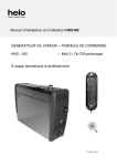
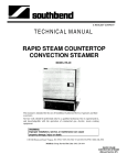
User and installation manual HNS T1
STEAM GENERATOR
1317 - … - 13 - 1 (HNS)
--
CONTROL PANEL
-- RA – 27 (T1)
For home and professional use
314 SHS 98-3 D
2
User and installation manual HNS-T1
Contents
Specifications
Easy maintenance
Accessories
3
3
3
General
Image of principle of installation
Overheating protector
Main switch
Ventilation
Automatic flushing
Automatic flushing with the DIP switch
Decalcification
Cleaning the steam room
Steame generator
3
4
5
5
5
5
5
6
6
7
Electrical connections
Heating elements
Connection diagrams
Selecting the steam generator output for the steam room
Troubleshooting
9
9
9
11
12
Use and installation of the control panel
Installation and connection of the remote control On/Off push button
15
18
3
User and installation manual HNS-T1
Specifications
Operating voltage
230V – 240V 1N~ / 2~,
230V 3~,
400V – 415V 3N~
Output options
Generator dimensions
Parallel coupling
3.4 / 4.7 / 6.0 / 7.7 / 9.5 / 12.0 / 14.0 kW
520 x 380 x 160 mm
See the connecting instructions for parallel coupling of
several generaors
IP 20
Floor/wall
Aisi 304, stainless steel
Aisi 314, stainless acid-proof steel
about 11 kg
(optional, Automatic drain valve)
(optional, Automatic drain valve)
Enclosure class
Installation
Water tank material
Water tank pipes
Weight when empty
Automatic flushing one hour after switching off
Interim rinsing during use
Electric water level adjustment
Electric overfill protector
Calcium repelling, self cleaning electrodes
Overheating protector
Safety valve
Digital control panel, Helo T1
(3.4 kW – 7.7 kW)
(3.4 kW – 14 kW)
(3.4 kW – 14 kW)
Easy maintenance
Replaceable heating elements (3 pcs)
The steam generator has an overheating protector equipped with a reset button.
Fill cap for deliming agent (citric acid) is located on the lid of the steamer.
Components easily replaceable, circuit board, heating elements, surface sensor.
Accessories
-
Scent pump, (Essence pump kit 0038130)
Scent pump canister 20 l (0038132)
Automatic flush and rinse cycle. (Automatic drain valve 4310130)
Steam nozzles (3.4 – 6.0 kW 1 piece, 7.7 – 9.5 kW 2 pcs, 12 – 14 kW 3 pcs) (7819604)
General
HNS-Touch steam generators are only intended for use in heating spa facilities. Using steam generators in other
areas than steam rooms can damage the building's structure.
The manufacturer is not responsible for damages caused if the unit has been used incorrectly or in a manner for
which the unit was not designed for.
Water and steam pipe connections must be made prior to connecting the unit into the mains.
Due care and attention must be taken when making the connections. Proper sealing must be ensured for all
extensions. A good extension must have at least taped over threaded connections, but it is recommended that
connections are soldered.
Testing the water before using the steam generator.
The test packet that comes with the steamer includes test slips, which can be used for testing the water hardness
number as follows:
Dip the test slip in water for about 1 second, take it out and shake off the excess water. After a minute, compare the
colour code appearing on the test slip with the code key in the packet.
4
User and installation manual HNS-T1
Test result:
< 3° dH,
> 4° dH,
> 7° dH,
> 14° dH,
> 21° dH,
Very soft water.
Soft water. Installing the decalcification device recommended
Medium-hard water. Installing the decalcification device recommended
Hard water. Installing the decalcification device recommended
Very hard water. Installing the decalcification device recommended
See page 6 for steam generator's operation time in hours before decalcification
The steam generator must be placed away from water and moisture (dry room). The room must be well ventilated as
the unit also produces heat. The maximum temperature of the room must not exceed 35°C. Recommended minimum
free space to sides and above the steamer is 30 cm. Adequate space for maintenance should also be planned for in
the placement of the unit. There should be a drain nearby for draining the tank.
The steam generator can be installed freestanding on the floor or on the wall using wall fittings. When using wall
fittings, ensure you use appropriate fittings and screws for the type of construction material of your walls. The steam
generator weighs about 17 kg when filled with water.
When the automatic drain valve is used, it is recommended you use wall installation so an adequate angle can be
ensured for draining of water.
Image of principle of installation
Thermostat
Steam room
520
16
0
Control panel
Water connection
380
1700mm
Power
supply
On/off push button
Steam pipe
Flushing
Locating the control panel
Generator wall mounting
HNS–T1 model, must be installed outside the steam room.
The thermostat cable is connected to the control panel. See the connection diagram for instructions.(see page 10)
The control panel cable can be extended with similar screened cable, max 50m.
Steam nozzle/nozzles are fitted approximately 200 to 400 mm from the floor underneath a bench or a seat, or onto
the wall so that the hot steam cannot burn anyone's feet. The steam nozzles are aimed towards the floor. When the
nozzles are installed, you must ensure to place them somewhere where nobody can accidentally touch them. The
steam temperature is +100 °C and it can cause injuries on contact.
If children or people with impaired reflexes use the steam room, the steam nozzle must be fitted with a protector that
prevents people from being exposed to the hot steam shower.
The thermostat is installed at about 1,700 mm high, preferably on the wall opposite the door. It is recommended to
seal the thermostat installation hole with appropriate sealing material, so that moisture cannot enter the wall
structures.
The steam room thermometer is installed at such a height that it shows the same reading as the control panel.
On / Off push button can be used for remote starting, the push button can be placed in the steam room or outside
it. For more detailed instructions see page 17.
5
User and installation manual HNS-T1
Overheating protector
The steam generator is equipped with an overheating protector. If the protector has tripped, find the reason for it
using the troubleshooting guide in the instruction manual. The overheating protector is reset by pushing a button.
NOTE: The overheating protector is located under the upper lid of the steam generator. Only a qualified electrician is
allowed to do this.
Main switch
There is a main switch at the bottom of one end of the steam generator, which is used only when the steam room is
not to be used for a long period of time.
The steam generator's automatic flushing and rinsing function will stop, if the power is switched off.
(Optional, Drain Kit)
Ventilation
It is not normally necessary to arrange ventilation for steam saunas that are used for less than two hours. steam
rooms that are used for more than two hours at a time need ventilation for functional and hygienic reasons. The
ventilation recommendation is 10 to 20 m3 per person per hour.
If there is an empty space above the ceiling of the steam room, it must not be completely sealed off. Make at least
one ventilation hole (100 mm x 100 mm) into the empty space, on the same wall with the door.
The Supply air valve may be a hole in the bottom part of the wall with the door or a gap under the door.
The Exhaust valve is placed in the ceiling or on a wall near the ceiling as far from the supply air valve as possible,
however not above the door or the seats. The exhaust valve is connected to an air conditioning channel going
outside
Forced ventilation. If natural ventilation is not adequate (e.g. negative pressure in the room where the fresh air is
taken from), the steam room must be equipped with forced ventilation. Its output must be equivalent of 10 to20 m³ of
ventilation per person per hour.
Automatic flushing
The Automatic flushing valve (Drain Kit, optional) reduces significantly the accumulation of calcium and impurities in
the water tank. For the flushing and rinsing Automatic drain valve to work, do not switch the power off from the switch
that may be fitted between the electrical cabinet and steam generator or the main switch before 80 minutes has gone
since the control panel's timer has switched the power off.
WARNING! The water is hot!
Automatic flushing with the DIP switch
This feature requires optional electric Drain Kit flushing valve
If the local water hardness exceeds 5 dH° or if the steamer is used for more than 4 hours a day, the steamer must be
drained regularly. Adjust the desired draining interval according to the connection diagram.
The DIP switches are found on the steam generator circuit board.
Factory setting: No automatic flushing or rinsing after bathing
4
3
2
1
No automatic
flushing.
ON
4
3
2
4
3
2
1
ON
2
1
ON
4
ON
3
Automatic flushing
after 4 hours.
1
Automatic flushing
after 1 hour.
Automatic flushing
after 2 hours.
4
No automatic
flushing or rinsing
after bathing.
Used with manual
flushing valve.
(factory setting)
3
2
1
ON
6
User and installation manual HNS-T1
Decalcification
Part of the calcium accumulated in the steam generator is flushed away during the automatic flushing and rinsing
cycle, but some of the calcium remains. Therefore it is important that the steam generator's automatic flushing
function is not out of order due to a faulty electric connection. The tank must be flushed after every use.
To prolong its service life and to reduce the need for manual decalcification, we recommend that steam generators
used in public facilities are connected to a water softening filter, which removes the calcium. This is especially
important, if the water hardness exceeds 5° dH (German hardness).
A water softening filter must not generate foam or produce harmful chemicals, which may give incorrect view of the
water level in the tank and cause the temperature switch to trip. (Heating elements will break down after some time.)
Manual decalcification is performed according to the chart below.
In normal private use, the need for decalcification is minimal, as the water is not particularly hard. However, the
steam generator must be decalcified at least once a year. This removes the calcium from the tank walls and heating
elements.
Steam generator decalcification
•
Start the steam generator and let it run until the water in the tank boils.
•
Stop the steam generator and wait for about 5 minutes.
•
Remove the connecting piece's lid nut at the top of the steam generator.
•
Pour the deliming agent (e.g. citric acid) into the tank via the connecting piece
using a funnel.
•
Replace the lid nut to the connecting piece and let the agent work.
•
The steam generator flushes and rinses the tank automatically after about an
hour and you can use the generator again.
Citric acid deliming agent is odourless and harmless and it does not harm the steam generator's components.
If another type of deliming agent is used, bathing during decalcification is not allowed.
As can be seen from the adjoining chart, the need for manual decalcification depends on water quality, steam
generator output and operation time.
Operation time in hours before decalcification. We recommend using softened water in public facilities
to reduce the need for manual decalcification.
Hours of operation, different hardnesses
Steam generator
output kW
3.4 kW
4.5 kW
6.0 kW
Amount of
deliming agent.
Citric acid
(1 bag 50g)
2 bags
2 bags
2 bags
Softened water
Soft water
Hard water
0.01 – 1° dH
1 – 3° dH
4 – 7° dH
Very hard
water
8 – 20° dH
7,000
3,800
2,600
2,300
1,300
900
900
500
300
350
190
130
7.7 kW
2 bags
1,700
600
200
90
9.5 kW
12 kW
14 kW
2 bags
2 bags
2 bags
1,500
1,300
1,200
500
400
300
180
160
150
80
70
60
Cleaning the steam room
Rinse the seats and the floor with warm water after every use (do not use a pressure washer). Clean the seats
regularly with mild detergent. Use ethyl alcohol or dilutine. Never use abrasives, strongly alkaline detergents or
solvents to clean the steam room seats and walls. Contact the manufacturer if necessary.
It is important to clean the floor carefully all the way to the corners. Use hot water, a brush and floor detergent that
removes dirt and grease.
7
User and installation manual HNS-T1
Steame generator
Safety valve installation
The safety valve is installed on the steam pipe with using the provided ½” T connector.
A separate downpipe directly to a drain or to the floor is installed on the safety valve. NOTE: Safety valve's downpipe
must not be connected to the steam generator's draining pipe or the steam pipe.. Use the provided sealing tape or
similar sealing on the threads.
Filling tube for the
deliming agent
Steam pipe ½”
Water connection, ¾”
Plug for the electromagnetic
flushing valve
Main switch
Water draining, 1/2"
Manual or electric valve
Strain relief clamp for
the control panel cable
Strain relief clamp for the
Heater connection cable
Image. Installation of the safety valve and the automatic drain valve
User and installation manual HNS-T1
8
Water and steam pipe connections
Connect the flexible ¾” water connection tube in the packaging to the water connection in the installation panel of the
unit and to the cold water piping of the building. The water pressure must be between 0.2 and 10 bars. The water
supply pipe must have a manual stop valve for stopping water supply to the unit, if the unit is not used for a prolonged
time.
Installation must follow local regulations
It is recommended to use at least 18x16 mm (steam generator’s size 3.4 kW-9.5 kW) and 22x20 mm (steam
generator’s size 12.0 kW- 14 kW) copper pipe or a silicone tube of similar type when connecting the steam pipe. The
steam pipe diameter must be the same for the whole length.
The steam pipe must be tilted upwards or downwards from the steam generator to the steam room. There MUST
NOT be any water seals or water pockets. The condensation water forming in the steam pipe must be allowed to
drain freely to the steam room or back to the generator. If a fragrance pump is connected to the generator, the pipe
must ALWAYS drain away from the steamer, so that the chemicals cannot get into the tank.
Recommended maximum length for the steam pipe is 5 metres.
It is recommended to always use additional insulation for the steam pipe, for both safety reasons and to prevent
water condensation in the pipe.
Clearance from an uninsulated steam pipe to flammable material such as wood must be at least 10 mm.
WARNING: Hot steam can cause burn injuries.
The electromagnetic valve for draining the steam generator’s size tank is fitted into the draining pipe. Alternatively
you may use a manual draining valve. Connect the downpipe (copper pipe with inner diameter of at least 16 mm)
Steam generator water draining into the downpipe. The downpipe is led to the nearest drain outside the steam room.
The temperature of the discharge water is 90 to 95° C.
IMPORTANT! No stoppers (valves, taps, etc.) may be fitted on the downpipe.
Regardless of where the downpipe is led, it must fall all the way from the steam generator to the drain. To ensure
adequate fall, you may have to place the steam generator on a wall mount or on a stand.
Steam generator’s tank should be drained after each use. This will extend the unit’s life and reduce chalk
build-up.
The product’s warranty will be void if the steam generator has been incorrectly installed or it has been used
in a manner other than described in the user manual.
The warranty also expressly excludes operational faults if they are caused by hard water i.e. water with high
levels of chalk, or otherwise impure water.
The steam generator must be maintained as described in the user manual.
9
User and installation manual HNS-T1
Electrical connections
The sauna heater must be connected to the mains by a qualified electrician and in compliance with current
regulations. The steam generator is connected with a semi-permanent connection. Use H07RN-F (60245 IEC 66) or
a corresponding type cables
Output
3.4
4.7
6.0
Generator connection cable
H07RN-F / 60245
IEC 66
mm2
400V-415V 3N~
5 x 1.5
5 x 1.5
5 x 1.5
7.7
9.5
12.0
14.0
kW
Fuse
A
3 x 10
3 x 10
3 x 10
Generator connection cable
H07RN-F / 60245
IEC 66
mm2
230V 3~
4 x 1.5
4 x 2.5
4 x 2.5
5 x 2.5
3 x 16
5 x 2.5
5x6
5x6
3 x 16
3 x 25
3 x 25
Fuse
Fuse
A
3 x 10
3 x 16
3 x 16
Generator connection cable
H07RN-F /
60245 IEC 66
mm2
230V-240V 1N~/2~
3 x 2.5
3 x 6.0
3 x 6.0
4x6
3 x 25
3 x 10
35
4x6
4 x 10
4 x 10
3 x 25
3 x 35
3 x 50
----------------
----------------
A
16
25
25
Steam generator's heating elements
Teho
Power
Leistung
3.0
3.4
4.7
6
7.7
9.5
12
14
Vastus / Element / Heizstäbe 230V
1
1,000W / SEPD 131
1,150W / SEPD 97
1,567W / SEPD 98
2,000W / SEPD 99
2,567W / SEPD 100
5,250W / SEPD 116
4,250W / SEPD 119
5,250W / SEPD 116
2
1,000W / SEPD 131
1,150W / SEPD 97
1,567W / SEPD 98
2,000W / SEPD 99
2,567W / SEPD 100
3,500W / SEPD 115
3,500W / SEPD 115
3,500W / SEPD 115
3
1,000W / SEPD 131
1,150W / SEPD 97
1,567W / SEPD 98
2,000W / SEPD 99
2,567W / SEPD 100
5,250W / SEPD 116
4,250W / SEPD 119
5,250W / SEPD 116
Connection diagrams
Electrical connections
3,4 - 14 kW 400V - 415V 3N~
G
A
B
C
D E
F
S
L1 L2 L3 N
3,4 - 7,7 kW 200V - 240V 1N~ / 2~
3,4 - 14 kW 230 V 3~
G
A
B
C
L1 L2 L3
D E
F
S
G
A
B
C
D E
F
200V - 240V~
S
10
User and installation manual HNS-T1
Optional equipment connections to the steam
generator terminal block.
40 41 42 43 P5 P6 B B
*) 1.5 mm² external voltage supply 200V – 240V, fuse 10A
P = fragrance pump control output
L
F = Fan control output
L
N
L
F
P
200V - 240V~
1.
2.
3.
4.
12
13
14
Max 24V
Steam generator/Parallel coupling of steam generators, Max 5 steamers.
Thermostat
Control panel HNS T1
Remote start On / Off push button. Connecting instructions for the electronic push button on page 18.
( 1. )
11
N
*)
*)
There are 3 milled billets in the plastic end for strain relief nipples
for separate control cables.
L
( 1. )
15
16 17
11
12
13
1.
14
15
16 17
11
12
13
3.
14
15
16
17
11
12
13
14
15
16
4.
17
18
19
20
21
3A
4B
5B
6B
2.
Connecting the control cables
NOTE: The cable between the steam generator and the control panel must be screened, e.g. LiYCY 6 x 0.25mm².
Maximum cable length 50 m
DIP-switches
Control panel T1
connecting terminal markings
HNS T1 steamer's circuit board
connecting terminal markings
11
User and installation manual HNS-T1
Selecting the steam generator output for the steam room
You can estimate the power requirement using the formula below.
3
Volume (m ) x K1 x K2 = Power requirement (kW)
Forced ventilation
No ventilation
Acrylic wall
Light wall: board + tile
Heavy wall: stone, concrete + tile
Very heavy wall: stone, concrete + tile
K1 = 0.75
K1 = 0.52
K2 = 1.00
K2 = 1.25
K2 = 1.50
K2 = 2.00
In heavy built steam rooms, it is recommended to use e.g. electric heating cable for warming the seats,
walls and floors.
Output
kW
Light structure, acrylic, tempered glass
No A/C
3,4
4,7
6,0
7,7
9,5
12,0
2 – 7 m³
3 – 8 m³
4 – 13 m³
6 – 15 m³
9 – 17 m³
12 – 24 m³
Air conditioned
2 – 6 m³
3 – 7 m³
4 – 9 m³
6 – 11 m³
9 – 13 m³
11 – 18 m³
14,0
18 – 30 m³
14 – 22 m³
Light
board
wall
+ tile
No A/C
2 – 6 m³
3 – 7 m³
4 – 8 m³
6 – 10 m³
9 – 14 m³
11 – 20
m³
14 – 24
m³
Heavy wall,
concrete,
stone
Air conditioned
2 – 5 m³
2 – 6 m³
3 – 7 m³
5 – 9 m³
8 – 13 m³
9 – 16 m³
12 – 18 m³
No A/C
Steam
kg / h
2 – 5 m³
2 – 6 m³
3 – 7 m³
5 – 9 m³
7 – 11 m
9 – 16 m³
Air conditioned
2 – 4 m³
2 – 5 m³
3 – 6 m³
4 – 8 m³
6–9m
8 – 12 m³
5
6
8
10
13
16
11 – 17 m³
10 – 14 m³
19
Table for selecting a steam generator based on the steam room volume and wall materials.
User and installation manual HNS-T1
12
Troubleshooting
WARNING! Steam generators may have several electric circuits.
Make sure that the device is completely dead before any troubleshooting operations.
Checks and troubleshooting.
In case of malfunction check that:
• the control panel and the steam generator are installed according to the connection diagrams
• the steam generator is installed properly according to this instruction manual
• the downpipe has adequate fall towards the drain
• the dirt filter is clean. The filter is in the incoming water connector. Open the pipe connector for cleaning, remove the
filter and remove all the chalk and dirt from it.
• there are no water pockets in the steam pipe or in the outgoing air conditioning pipe.
• there are no sharp bends in the steam pipe (bend radius must be at least 50 mm).
• any tap on the incoming water pipe to the steam generator is open.
• the steam room's structure and air conditioning match the installation and building instructions.
Troubleshooting chart
Possible causes and suggestions for fixes
Warming up takes abnormally long.
Cause: Inadequate power output of the steam generator. See output chart.
Action: Replace with more powerful steam generator.
Cause: Excessive ventilation of the steam room.
Action: Reduce ventilation so that it is 10-20 m³ per person per hour.
Cause: Blown fuse in the electrical cabinet
Action: Replace the fuse.
Action: Replace the heating element
Cause: The sensor is too close to the steam shower. See test 2.
Action: Move the sensor to another location or redirect the steam shower.
The steam room does not warm up or there is no steam.
Cause: Blown fuse in the electrical cabinet
Action: Replace the fuse.
Cause: No water is coming to the steam generator.
Action: Open the incoming water tap.
Cause: The control panel is not set up right.
Action: Check the time and temperature settings.
Cause: Dirt filter is blocked.
Action: Remove the dirt filter from the incoming water connector and clean it.
Cause: The electromagnetic valve for the incoming water is stuck.
Action: Remove the electromagnetic valve and clean it.
Cause: Too much chalk has accumulated in the steam generator's water tank. See test 1.
Action: Clean the water tank and surface sensor's pin, and replace the heating elements, if necessary.
Cause: The steam generator is connected for incorrect voltage.
Action: Check the voltage and the steam generator's connections. See Connection diagram.
Cause: The overheating protector has tripped. See test 4.
Action: Check and fix possible faults in the steam pipe, e.g. blocks caused by several sharp bends, water pockets or
significantly reduces inner diameter of the pipe. It is also possible that the tank has been filled with chalk accumulation or impurities. See the previous entry.
Cause: Fault in the circuit board, control panel or electromagnetic valve.
Action: Replace the faulty part.
User and installation manual HNS-T1
13
Warm water comes out of the steam nozzle, and there is little or no steam in the steam room.
Cause: The electromagnetic valve for the incoming water is stuck open because of dirt or electric fault. See test 3.
Action: Remove the electromagnetic valve and clean it. Fix the electric fault.
Cause: The electromagnetic valve is broken.
Action: Replace the electromagnetic valve.
Cause: Fault in circuit board.
Action: Replace the circuit board.
Warm water comes out of the steam nozzles in pulses or as weak continuous stream with steam.
Cause: Small water pocket in the steam pipe.
Action: Remove the water pocket.
Cause: Too much of the steam pipe is uninsulated.
Action: Insulate the steam pipe.
Warm water comes out of the steam generator's downpipe all the time.
Cause: Automatic electromagnetic flushing valve is stuck open.
Action: Stop the steam generator. Try again after 80 minutes. If the fault remains, remove the automatic electromagnetic flushing valve and clean it.
Banging noise from the water pipes when the electromagnetic valve opens or closes.
Cause: Inadequate connection in the water pipe coming into the steam generator.
Action: Mount the water pipe securely on the wall.
Cause: Recoil effect in the incoming water pipe.
Action: Install about 1 metre of pressure-proof reinforced rubber hose into the steam generator end of the water pipe.
Safety valve opens or the overheating protector trips.
Cause: Steam pipe is blocked. See test 4.
Action: Remove the block.
Cause: The inner diameter of the steam pipe is significantly reduced. See test 4.
Action: Replace the pipe or the connection where the inner diameter is reduced (minimum inner diameter is 16 mm).
Cause: Several sharp bends in the steam pipe. See test 4.
Action: Make the bends less sharp.
Cause: There is a large water pocket in the steam pipe. See test 4.
Action: Install the steam pipe so that a water pocket does not form.
Steam generation is irregular from the beginning.
Cause: The sensor is misplaced. See test 2.
Action: Move the sensor or redirect the steam shower.
Cause: Chalk or other impurities in the dirt filter.
Action: Remove the dirt filter and clean it.
User and installation manual HNS-T1
14
TEST 1.
Checking chalk deposits in the water tank.
Open the top lock nut in the steam generator. Lower a torch bulb that is connected to a battery with wires into the
opening and light up the water tank's inside. If there is more than 3 cm chalk on the bottom, the steam generator has
not been serviced and the chalk has not been removed according to the instructions.
It is also possible that the flushing and rinsing automation is not working. Check that the steam generator power has
not been switched off after bathing with a switch that may fitted in the supply line. You can switch the power off from
this switch only 80 minutes after the control panel has switched the power off.
Check the automatic flushing function by setting a bucket with a volume of about 12 litres under the downpipe. Start
the steam generator for about 15 minutes. Switch off the steam generator exactly the same way you normally do
after bathing. Wait at least 80 minutes and check if the bucket is filled with water. If it is not filled, there is a problem
with the steam generator's electric connections or the power supply has been switched off on the wire from electrical
cabinet directly to steam generator. It is also possible that the exhaust valve is blocked or the circuit board is faulty.
TEST 2.
Checking the thermostat sensor.
Wet a small towel with water and hang it on the sensor. If the steam generator starts producing steam within 20
minutes, the sensor works. However, it is placed in a wrong place or the temperature setting is too low. If the steam
production does not start, use the troubleshooting chart to find the fault.
TEST 3.
Checking the electromagnetic valve.
Stop the steam generator from the control panel. If water still flows from the steam nozzles 10 minutes after the
power has been switched off from the control panel, there is dirt in the electromagnetic valve. Remove the
electromagnetic valve and clean it.
If the water flow stops within 10 minutes after the power has been switched off from the control panel, the fault is in
the electrics (faulty connection or circuit board). It is also possible that too much chalk has accumulated in the water
tank. See test 1.
TEST 4.
Checking the steam pipe using the safety valve or the overheating protector.
Remove the steam pipe from the steam generator. Start the generator and let it run for about one hour. If the safety
valve or the overheating protector does not trip during the test, there is a block in the steam pipe that prevents the
steam flow. Follow the instructions in the troubleshooting chart.
The product’s warranty will be void if the steam generator has been incorrectly installed or it has been used
in a manner other than described in the user manual.
The warranty also expressly excludes operational faults if they are caused by hard water i.e. water with high
levels of chalk, or otherwise impure water.
The steam generator must be maintained as described in the user manual.
15
User and installation manual HNS-T1
Use and installation of the control panel for HNS – T1
Control panel RA27 (T1)
Loosen the screw at the bottom of the control panel.
Install the bottom piece for the control panel
NOTE: If the control panel is installed
in a humid place, use the provided
seal.
Control panel dimensions:
-
Height 140mm
Width 80mm
Depth 22 mm
Remove the control panel frame and lid.
Install and connect the cable. For
connecting instructions, see page 10.
16
User and installation manual HNS-T1
Control panel T1
START (KÄYNNISTYS)
Display
TEMPERATURE
(LÄMPÖTILA)
TIMER (AJASTUS)
Activated
functions
SETTINGS
(ASETUKSET)
Touch display
buttons
Button functions:
Takes you from a submenu to the front page.
Step back. Shows the temperature and the time when pressed on the front page.
Lighting control on/off.
OK button accepts the modified setting or move forward on e.g. time settings.
Arrow button, moves upwards in the menus.
Arrow button, moves downwards in the menus.
Start and stop. Select with the arrow buttons and press OK.
Changing the temperature setting.
Pre-set time setting. You can set the pre-time setting between 0 and 23.59 hours.
Settings. Move to the next menu.
Automatic locking, time setting adjustment 15 - 60 s. Settings in the menu, on/off.
The locking is opened from the settings menu or by pressing simultaneously
for 2 seconds the
symbols.
17
User and installation manual HNS-T1
Settings
The following submenus are found under the menu
-
Status. Shows the temperature and the time
Set the time. Time setting.
Language. You can select the language from a menu.
Display. Setting the display to sleep, time setting 3–60 s.
Automatic locking. Locks the buttons after 15– 60 seconds,
on/off.
Vibration. Vibration function of the controller on/off.
Service. Enter the PIN code to access the service menu.
The service PIN code is 124.
Settings
Status
Set the time
Display
Automatic locking
Vibration
Service
Service
The following submenus are found under the menu
-
-
Maximum time. In steam bathing use 0–24 hours.
Maximum temperature. Temperature setting 20–55 .
°C or °F. Alternative temperature display.
24 or 12 hours. Alternative time display.
Light switch. Lighting controls, continuous or momentary.
Continuous, the lights are always on when the steam generator is on.
Momentary, lights are only on when the light button is pressed.
Scent – Fan.
Scent pump control on/off.
Fan, Air conditioning control after the steam generator has stopped.
Automatic 30 minutes.
Time with manual setting 20–60 minutes.
Manual control on/off.
Decalcification. Decalcification alarm limit setting 0–100 hours.
Show an alarm on the display after the hour setting is up.
Operation time. Steamer operation time counter.
Factory setting. PIN code 421.
Test. During service or in case of a fault you can test
different relay outputs and check that they work.
Service
Maximum time
Maximum temperature
O
O
C or F
24 or 12 hours
Light switch
Scent – Fan
Decalcification
Factory settings
Test
Factory setting
Select region
-
Europe
USA
Other regions
-
Select the region where the controller is used
Europe, time and temperature settings according to the
European regulations.
USA, settings according to the American regulations
Other regions.
Select Europe. Select the control panel language
from the language menu, English, Swedish or Finnish.
Select the control panel use, sauna or steam bathing.
Select steam bathing and press OK.
Set the maximum steam bathing time 0–24 hours.
Set the time in the control panel.
18
User and installation manual HNS-T1
Remote control On/Off push button
Button function
The steam generator can be started remotely with the ON/OFF push button. The LED light on the push button
lights up to show that the steam generator has started. The steam generator runs according to the maximum time
and temperature set in the control panel T1. The steam generator can also bu turned off with the push button.
After the steam generator stops the flushing and rinsing functions activate.
See page 5.
Led indicator
The push button is filled with
sealant, therefore it may be installed
in the steam room.
The push button may be installed
through a wall (acrylic walls) or
by making a suitable hole, where
the push button can be embedded and
sealed with appropriate
sealant.
Surface installation boxes may also
be used, if necessary, they do not
need to be tight, because the actual
push button is moisture resistant.
ON – OFF button
40 mm
Retaining nut
46 mm
32 mm
24 mm
11
12
13
14
15
16
17
18
19
20
Brown
Yellow
White
Green
Brown and yellow
White
Green
Connection of the push button
21
Control panel T1 Multiway terminal block
On / Off push button
19
User and installation manual HNS-T1
ROHS
Ympäristönsuojeluun liittyviä ohjeita
Anvisningar för miljöskydd
Tämän tuotteen käyttöiän päätyttyä sitä ei
saa hävittää normaalin talousjätteen
mukana, vaan se on toimitettava
sähkö- ja elektroniikkalaitteiden kierrätykseen
tarkoitettuun keräyspisteeseen.
Denna produkt får inte kastas med
vanliga hushållssopor när den
inte längre används. Istället ska den
levereras till en återvinningsplats
för elektriska och elektroniska apparater.
Symboli tuotteessa,
käyttöohjeessa tai
pakkauksessa tarkoittaa sitä.
Symbolen på produkten,
handboken eller
förpackningen refererar till detta.
Valmistusaineet ovat kierrätettävissä merkintänsä
mukaan. Käytettyjen laitteiden
uudelleenkäytöllä, materiaalien hydöyntämisellä
tai muulla uudelleenkäytöllä teet arvokkaan teon
ympäristömme hyväksi.
Tuote palautetaan ilman kiuaskiviä ja verhouskiviä
kierrätyskeskukseen.
De olika materialen kan återvinnas enligt
märkningen på dem. Genom att återanvända,
nyttja materialen eller på annat sätt återanvända
utsliten utrustning, bidrar du till att skydda vår
miljö.
Produkten returneras till återvinningscentralen
utan bastusten och eventuell täljstensmantel.
Tietoa kierrätyspaikoista saat
kuntasi palvelupisteestä.
Vänligen kontakta de kommunala myndigheterna
för att ta reda på var du hittar närmaste
återvinningsplats.
Instructions for environmental protection
Hinweise zum Umweltschutz
This product must not be disposed with
normal household waste at the end of
its life cycle. Instead, it should be
delivered to a collecting place for the recycling
of electrical and electronic devices.
Dieses Produkt darf am Ende seiner LebensDauer nicht über den normalen Haushaltsabfall
Entsorgt werden, sondern muss an einem
Sammelpunkt für das Recycling von elektrischen
und elektronischen Geräten abgegeben werden.
The symbol on the product, the
instruction manual or the
package refers to this.
Das Symbol auf dem produkt, der
Gebrauchsanleitung oder der
Verpackung weist darauf hin.
The materials can be recycled according to the
markings on them. By reusing, utilising the
materials or by otherwise reusing
old equipment, you make an important
contribution for the protection of our environment.
Please note that the product is returned to the
recycling centre without any sauna rocks and
soapstone cover.
Please contact the municipal administration
with enquiries concerning the recycling place.
Die Werkstoffe sind gemäß ihrer Kennzeichnung
wiederverwertbar, Mit der Wiederverwendung,
der stofflichen Verwertung oder anderen Formen
der Verwertung von Altgeräten leisten Sie einen
wichtigen Beitrag zum Schutze unserer Umwelt.
Dieses Produkt soll ohne Steine und
Specksteinmantel an dem Sammelpunkt für
Recycling zurückgebracht werden.
Bitte erfragen Sie bei der Gemeindeverwaltung
die zuständige Entsorgungsstelle.