1
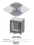
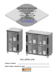
ER136 – ER236 series / série 5000
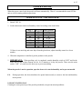
Product / Produit:
Serial number / Numéro de série:
IMPORTANT SAFETY INSTRUCTIONS
SAVE THESE INSTRUCTIONS
DANGER
TO REDUCE THE RISK OF FIRE OR ELECTRIC SHOCK
CAREFULLY FOLLOW THESE INSTRUCTIONS
TABLE OF CONTENTS
(table des matières :page suivante)
Description ___________________________________________________________________ A-1
Introduction________________________________________________________________ A-2
Construction _______________________________________________________________ A-2
Shipping __________________________________________________________________ A-2
Installation warnings_________________________________________________________ A-4
Distances to respect__________________________________________________________ A-4
Installation ________________________________________________________________ A-6
Operation of the retarder / proofer ______________________________________________ A-8
Timer programming instructions (Grasslin DIGI20E-120) ___________________________ A-9
Example of timer adjustement ________________________________________________ A-10
Timer programming instructions (Grasslin FM1D20E-120) _________________________ A-12
Power failure______________________________________________________________ A-15
Operation of the proofer _____________________________________________________ A-15
Troubleshooting ___________________________________________________________ A-24
Unit maintenance and cleaning________________________________________________ A-26
Maintenance: Water compartment _____________________________________________ A-28
Component parts ________________________________________________________________B-1
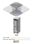
ER136 Front view ____________________________________________________________B-2
ER136 Top view _____________________________________________________________B-4
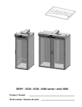
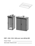
ER236 Top view _____________________________________________________________B-6
Control Panels__________________________________________________________________C-1
ER136 1PH 220V 60HZ _______________________________________________________C-2
ER136 1PH 208 - 240V 60HZ ___________________________________________________C-3
ER236 1PH 220V 50HZ _______________________________________________________C-4
ER236 1PH 208 - 240 60HZ____________________________________________________C-5
Warranty ________________________________________________________________________1
FAM ER [LIVRET].doc
Rev. 01/2010
IMPORTANT INSTRUCTIONS DE SÉCURITÉ
CONSERVEZ CE MANUEL D’INSTRUCTIONS
DANGER
AFIN DE RÉDUIRE LES RISQUES D'INCENDIE OU D'ÉLECTROCUTION
SUIVRE CES INSTRUCTIONS AVEC SOIN
TABLE DES MATIÈRES
Description ____________________________________________________________________A-1
Introduction ________________________________________________________________A-3
Construction ________________________________________________________________A-3
Expédition __________________________________________________________________A-3
Avertissement lors de l'installation_______________________________________________A-5
Distances à respecter _________________________________________________________A-5
Installation _________________________________________________________________A-7
Opération de l'étuve / retardeur ________________________________________________A-16
Programmation de la minuterie (Grasslin DIGI20E-120) ____________________________A-17
Exemple de programmation ___________________________________________________A-18
Programmation de la minuterie (Grasslin FM1D20E-120)___________________________A-20
Panne de courant ___________________________________________________________A-23
Opération de l'étuve _________________________________________________________A-23
Dépannage ________________________________________________________________A-25
Entretien et nettoyage de l’appareil _____________________________________________A-27
Entretien: Unité d’évaporation_________________________________________________A-28
Pièces composantes _____________________________________________________________B-1
ER136 Vue de face ___________________________________________________________B-2
ER136 Vue de dessus _________________________________________________________B-4
ER236 Vue de Dessus _________________________________________________________B-6
Panneaux de contrôle ____________________________________________________________C-1
ER136 1PH 220V 60HZ________________________________________________________C-2
ER136 1PH 208 - 240V 60HZ ___________________________________________________C-3
ER236 1PH 220V 50HZ _______________________________________________________C-4
ER236 1PH 208 - 240 60HZ____________________________________________________C-5
Garantie ________________________________________________________________________1
FAM ER [LIVRET].doc
Rev. 01/2010
SECTION A:
DESCRIPTION
/ DESCRIPTION
A-2
INTRODUCTION
This equipment is manufactured with first quality material by experienced technicians. Proper installation and
maintenance will guarantee a reliable service for years to come.
A nameplate fixed to the front of the proofer specifies the serial number, model number, number of phase,
amperage, voltage and frequency.
Drawings and replacement part numbers are included in this manual. The electrical diagram is affixed in the
control panel located on the top of the proofer.
ATTENTION
DOYON is not responsible for damages to the property or the equipment caused by
personnel who is not certified by known organisations. The customer is responsible for
finding qualified technicians in electricity and plumbing for the installation of the
oven.
CONSTRUCTION
You just bought the most advanced proofer in the world, the "DOYON" technology at its best. This proofer is
manufactured using the highest quality components and material.
The DOYON equipments are designed with parts that are easy to find.
SHIPPING
For your safety, this equipment has been verified by qualified technicians and carefully crated before
shipment. The freight company assumes full responsibility concerning the delivery in good condition of the
equipment in accepting to transport it.
IMPORTANT
RECEPTION OF THE MERCHANDISE
Take care to verify that the received equipment is not damaged before signing the delivery receipt. If a
damage or a lost part is noticed, write it clearly on the receipt. If it is noticed after the carrier has left, contact
immediately the freight company in order that they do their inspection.
We do not assume the responsibility for damages or losses that may occur during transportation.
A-3
INTRODUCTION
Votre équipement est fabriqué avec des matériaux de première qualité par des techniciens d'expérience.
Une utilisation normale et un entretien adéquat de l'équipement vous assureront plusieurs années de bon
service.
Une plaque signalétique, située à l’avant de l’étuve, mentionne le numéro de série, le numéro du modèle, le
nombre de phases, l’ampérage, le voltage et la fréquence.
Les dessins et les numéros de pièces de rechange sont inclus dans ce manuel. Le plan électrique est affiché
dans la boîte de contrôle sur le dessus de l’étuve.
ATTENTION
Équipement Doyon Inc. ne peut être tenu responsable pour les dommages causés à la
propriété ou à l'équipement par du personnel non certifié par des organismes accrédités.
Le client a la responsabilité de retenir les services d'un technicien spécialisé en électricité
et d'un plombier qualifié pour l'installation de l'étuve.
CONSTRUCTION
Vous avez maintenant en votre possession l’étuve la plus performante présentement disponible sur le marché,
une étuve utilisant la technologie "Doyon" à son meilleur. Cette étuve est fabriquée avec des matériaux de
première qualité.
L’étuve DOYON est fabriquée avec des matériaux et pièces composantes facilement disponibles sur le marché.
EXPÉDITION
Pour votre protection, cet équipement a été vérifié et emballé avec précaution par des techniciens qualifiés
avant son expédition. La compagnie de transport assume la pleine responsabilité concernant la livraison
de cet équipement en bon état en acceptant de le transporter.
IMPORTANT
RÉCEPTION DE LA MARCHANDISE
Avant de signer le reçu de livraison, prenez soin de vérifier dès la réception si l'équipement n'est pas
endommagé. Si un dommage ou une perte est détecté, écrivez-le clairement sur le reçu de livraison ou
votre bon de transport et faites signer le livreur. Si le dommage est remarqué après le départ du
transporteur, contactez immédiatement la compagnie de transport afin de leur permettre de constater les
dommages causés.
Nous ne pouvons assumer la responsabilité pour les dommages ou les pertes qui pourraient survenir
pendant le transport.
A-4
INSTALLATION WARNINGS
FOR YOUR SAFETY
DO NOT STORE OR USE GASOLINE OR OTHER FLAMMABLE VAPORS
AND LIQUIDS IN THE VICINITY OF THIS OR ANY APPLIANCE.
IMPORTANT
INSTALLATION AND SERVICE
Installation and service must be done by specialized technicians. Contact a certified electrician and plumber
for set up.
The proofer must be connected to the utility and electrically grounded in conformity to the effective local
regulations. If these are not established, the oven must be connected according to the Canadian Electrical
Code (CSA-C22.1-XX) or National Electrical Code (NFPA 70-XX). Refer to last edition year for XX.
DISTANCES TO RESPECT
●
Top of the proofer: a clearance of 24’’ to the ceiling must exist to permit maintenance.
●
Back and sides:4’’ clearance.
A-5
AVERTISSEMENT LORS DE L'INSTALLATION
POUR VOTRE SÉCURITÉ
NE PAS EMMAGASINER OU UTILISER D'ESSENCE OU AUTRES VAPEURS
ET LIQUIDES INFLAMMABLES À PROXIMITÉ DE CET ÉQUIPEMENT
OU DE TOUT AUTRE APPAREIL.
IMPORTANT
INSTALLATION ET SERVICE
L'installation et le service doivent être faits par un technicien spécialisé. Contactez un technicien spécialisé
en électricité pour l'installation d’une prise de courant adéquate.
Cet appareil doit être branché et mis à la terre (grounded) conformément aux règlements effectifs de votre
localité. Si aucune réglementation n'est établie, l’appareil doit être branché conformément au Code
Canadien de l’électricité CSA 22.1-XX ou au Code National de l'Électricité NFPA 70-XX. Référez vous à
l’année de la dernière édition pour XX.
DISTANCES À RESPECTER
●
Dessus de l'étuve : Il est obligatoire d’avoir au moins 24’’ entre le dessus de l’étuve et le plafond afin
d’effectuer le service.
●
Arrière et côtés de l'étuve :une distance de 4’’ est nécessaire.
A-6
INSTALLATION
IN GENERAL
Take off the packaging material with care. Take off all the material used for packing and accessories.
If the equipment is delivered with casters, always lock them after installation and use flexible wire. It must
also be installed with restraining device (chain comes with the oven) to guard against transmission of strain
to the gas supply and connectors.
1. To the electrician
Electrical supply installation must be in accordance with the electrical rating on the nameplate.
WARNING
The electrician must make sure that the supply cable does not come in contact with the
oven top which becomes hot.
2. To the plumber
This equipment is to be installed to comply with the applicable federal, state or local plumbing codes.
Connect the steam system (1/4 NPT) to the cold water distribution network.
We highly recommend to use a water softener to eliminate minerals in the water.
We suggest you to use CUNO # CFS6135 (Doyon part number PLF240).
WARNING
Do not adjust the needle valves, it has been done at the factory.
A-7
INSTALLATION
EN GÉNÉRAL
Ouvrir avec soin l'emballage de votre équipement. Enlever tous les matériaux utilisés pour l'envelopper
ainsi que les accessoires.
Si l'appareil est muni de roulettes, veuillez toujours les bloquer après l'installation et utiliser un cordon
flexible. De plus, des équipements de retenues (chaîne comprise avec le four) doivent être installés pour
empêcher le tuyau d'alimentation et les connecteurs de subir des tensions lorsque le four est déplacé.
1. À l'électricien
L'installation de l'alimentation électrique des fours doit être conforme avec la source électrique spécifiée
sur la plaque signalétique de l’appareil.
AVERTISSEMENT
L'électricien doit s'assurer que le câble d'alimentation ne touche pas le dessus du four à
cause du degré élevé de chaleur dégagée par celui-ci.
2. Au plombier
Relier le système de vapeur (1/4 NPT) au réseau de distribution d'eau froide.
Il est fortement recommandé d'installer un adoucisseur d’eau à l’entrée de l’appareil afin d’éliminer les
minéraux dans l’eau.
Nous recommandons la marque CUNO # CFS6135 (numéro de pièce DOYON PLF240).
AVERTISSEMENT
Ne jamais changer l'ajustement des valves à aiguille pré-ajustées.
A-8
OPERATION OF THE RETARDER / PROOFER
1. Program the timer control before turning on the main switch.
2. Turn the power switch
3. Select
to the "1" position.
for manual proofer or
for auto retarder/proofer.
4. "
"In this position, it is on proofer mode. The unit heats up to the settings of the humidity control (
about 100°F / 37°C ), and then the humidity increases up to the humidity settings (80% to 85%
humidity). The refrigeration unit can not work at the same time as the proofer.
"
"In this position, you can program how long the unit will work in the proofer mode and how
long it will work in the refrigeration mode. Don't worry, both can not work at the same time. See timer
programming instructions.
(See operating instructions for the timer setting and example on next pages).
TIMER STAGE:
Timer "ON" =
Timer "OFF"=
= STARTING time of proofer
= STARTING time of refrigeration
NOTE: THE STARTING TIME OF PROOFER AUTOMATICALLY STOPS THE REFRIGERATION.
Button ‘OVERRIDE’ : Used for anticipating manually the starting time of the next program and
vice versa.
5. Adjust the thermostat at the desired temperature (100°F / 37°C).
6. Adjust the humidity at the desired value ( 80% ).
7. Adjust the refrigeration at the desired temperature.
**We suggest you to turn off the light when the unit is used as a refrigerator, because the light
heats. Then you will save energy.
8. Loading the proofer. When used on manual mode "
control disappears before loading.
Leave the product inside until it is ready to bake.
" , wait until the "PREH" on the humidity
9. When proofing cycle is completed, turn the switch "OFF" or to . "AUTO" mode.
When the proofer is not in operation, open the doors to let out the humidity and then prevent
mold.
P.S. : The doors should not be opened unnecessarily to conserve the heat and humidity in the proofer.
A-9
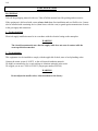
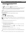
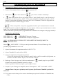
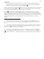
TIMER PROGRAMMING INSTRUCTIONS (GRASSLIN DIGI20E-120)
The circular keypads are positioned to provide a sequential path for programming.
Starting with Prog to select a program and then HAND
to select heating (ON) or cooling (OFF).
Then press h for hour, m for minute and finally Day to select day or days of the week.
If an input is missing or incomplete, the missing segments will flash when the
or Prog key is
depressed. For example, if no "ON" or "OFF" is selected, the "ON" symbol will flash.
The missing entry must be completed before programming can resume.
While programming, pressing the h,
parameter.
m, or Day key longer than 2 seconds will cause a rapid roll of the
A program consists of
1. Press Prog key
2. Select "ON " or "OFF"
3. Set hour and minute
4. Set day or multiple days on which it is to occur
Note: The program have to be coherent. So it is recommended to use Res to reset the program before
doing any important modification to the program in a way to avoid conflict between the different
programs.
A flashing display indicates either incomplete data entry or the battery is low (more than 5 days).
The ±1h key sets clock time up or down 1 hour for daylight savings time adjustment in the spring and
fall.
SETTING TIME AND DAY OF CLOCK.
1. Select the cycle of 12:00 hours or 24 hours.
2. Depress and hold h key while pressing ±1h key to toggle between one or the other cycle and from
AM to PM.
3. Press and hold down
key.
4. If setting the time when daylight savings time is in effect, press ±1h key once.
5. Set hour with h key and if AM or PM does not appear in display, it’s a cycle of 24 hours.
6. Set minutes with m key.
7. Press Day key repeatedly to the day of the week (1 is Monday, 7 is Sunday).
8. Release
key.
A-10
EXAMPLE OF TIMER ADJUSTEMENT
Monday to Saturday: proofer mode starts at 6:00 Am and stops at 8:00 Pm.
: retarder (fridge) mode starts at 8:00 Pm and stops at 6:00 Am.
Sunday: proofer mode starts at 7:00 Am and stops at 5:00Pm.
: retarder (fridge) mode starts at 5:00 Pm until next mode (proofer mode at 6:00 Am on Monday).
Note: On automatic mode, the proofer or the retarder is on. When the proofer stops, the retarder
automatically starts.
1. The time and day should have been set before doing this example (see previous pages).
2. Press PROG twice, you should see FR=20. Press
to go back to the hour display.
If you don’t have FR=20, you should do a reset by pressing RES and return to #1. You have to do this
to avoid the existing program to overlap the new program.
3. Press PROG, you should see 1234567, select the days of the week by pressing DAY until you get
123456.
4. Select the hour (6:00 Am) by pressing H (hour) and M (min).
5. Press the HAND until you get
on the bottom of the display.
6. Press PROG, you should see 1234567, select the days of the week by pressing DAY until you get
123456.
7. Select the hour (8:00 Pm) by pressing H (hour) and M (min).
8. Press the HAND until you get
on the bottom of the display.
9. Press PROG, you should see 1234567, select the days of the week by pressing DAY until you get 7.
10. Select the hour (7:00 am) by pressing H (hour) and M (min).
11. Press the HAND until you get
on the bottom of the display.
12. Press PROG, you should see 1234567, select the days of the week by pressing DAY until you get 7.
13. Select the hour (5:00 Pm) by pressing H (hour) and M (min).
14. Press the HAND until you get
15. Press
.
on the bottom of the display.
A-11
IMPORTANT :
The timer’s exit will change configuration ("ON " or "OFF") only when determined by programming.
Thus, if the exit is not at the desired value after ending programming, it can be changed using the
HAND key.
Example : you finished programming at 2:00 PM, the exit is at “OFF”, but should be at “ON” from 8:00
AM to 5:00 PM. Press on the HAND
key to temporarily activate the exit. The exit’s configuration
will continue according to programming of next transition, at 5:00 PM.
When
is shown (regular operation mode), it is possible to give a temporary manual priority using
HAND key (Cancellation or “Override”). This priority changes for the opposite displayed mode each time
the key is pressed and will remain until next change of configuration. It is possible to program several
consecutive cycles “ON” or “OFF” to return to the programmed mode and counter the cancellation effect
for an extended period.
REVIEW AND CHANGE PROGRAM
It is possible to review the program at any time by pressing on the PROG. key. Each time the key
PROG. is pressed, the program will appear in entry order.
To modify the program, select the part that has to be changed and enter the new dates and hours as
described previously. The existing program will be replaced by the new entries. Press PROG to save the
modifications.
To erase an individual program, select the program as described previously and press the M key
and the H key until "- -" appears. Then, press PROG or
until "- -" flickers. After a couple seconds, the
program will be erraced.
A-12
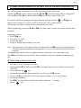
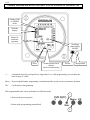
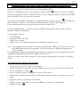
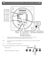
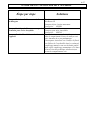
TIMER PROGRAMMING INSTRUCTIONS (GRASSLIN FM1D20E-120)
Setting of 24h
or AM/PM
mode
Weekday
display
Manual or
automatic
operation
Switching
status display
ON/OFF
Reset
+/- :
Summer/winter clock
changes
(Areas concerned only)
Proofer
Refrigeration
(Adjustment keys) By pressing the key longer than 2 sec. while programming, you can adjust the
timer in steps of 5 units
Menu : By pressing this button, progamming is terminated and the system reverts to automatic operation
OK :
Confirmation of programming
This programmable timer can be used under two different modes
1
1.Reset mode (preset program)
2.Menu mode (programming personalized)
2
A-13
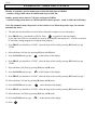
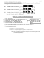
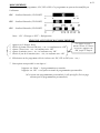
RESET MODE (PRESET PROGRAMMING)
This mode includes 3 programs. (P01, P02 and P03). These programs cannot be modified by the
user.
P01
Monday to Sunday (1X ON/OFF)
P02
Monday to Sunday (2X ON/OFF)
P03
Monday to Sunday (3X ON/OFF)
Note: `ON' = Proofer and `OFF' = Refrigeration
SEQUENCE TO FOLLOW FOR THE RESET MODE
1.
2.
3.
4.
5.
Press ‘Reset’ button
Select 24h or AM/PM (with + or -) and confirm with ‘OK
Set hour (with + or -) and confirm with ‘OK’
Set minutes (with + or -) and confirm with ‘OK’
Set week day (with + or -) and confirm with ‘OK’
These steps are used to
adjust the hour. If the hour
is correct, press `OK' until
step 6
6. Select preset program such that described above this, P01, P02 or P03 (with + or -)
7. Two options are now possible :
! Press ‘Menu’ = terminate programming
! Press ‘OK’ = Going through preset programs to modify selection
!This adds programming personalized to that preset (See in following page for the
personalized programming)
A-14
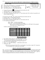
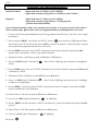
SEQUENCE TO FOLLOW FOR THE MENU MODE (PERSONALIZED PROGRAM)
1.
2.
3.
4.
5.
Press ‘Menu’ button
Select 24h or AM/PM (with + or -) and confirm with ‘OK’
Set hour (with + or -) and confirm with ‘OK’
Set minutes (with + or -) and confirm with ‘OK’
Set week day (with + or -) and confirm with ‘OK’
6.
7.
8.
9.
Program ON (prog 01)
(Starting proofer) and confirm with ‘OK’
Set hour (with + or -) and confirm with ‘OK’
Set minutes (with + or -) and confirm with ‘OK’
Set week day, individual or blocks (with + or -) and confirm with ‘OK’ (See below for possible week
blocks and individual days)
These steps are used to
adjust the hour. If the
hour is correct, press
`OK' until step 6
10. Program 02 (prog 02)
(Starting refrigeration) and confirm with ‘OK
11. Set hour (with + or -) and confirm with ‘OK’
12. Set minutes (with + or -) and confirm with ‘OK’
13. Set week day, individual or blocks (with + or -) and confirm with ‘OK
14. Two options are now possible :
! Press ‘Menu’ = terminate programming
! Press ‘OK’ = go to a new program ON setting
There are up to 20 memory locations available for 10 OFF and 10 ON commands.
This program can be changed at any time.
Possible week blocks or individual days
Monday
Tuesday
Wednesday
Thursday
Friday
Saturday
Sunday
*
*
*
*
*
*
*
*
-
*
*
*
*
*
*
*
*
*
*
*
*
*
DELETE A PROGRAM
1. Press ‘Menu’ button, then press ‘OK’ until getting the ‘prog 01’
2. Then select the program that you want to erase with ‘+ or –‘ keys
(you can also press `OK' until the desired program appeared)
3. Press ‘OK’ to go at the flicker hour
4. Press ‘+ or –‘ key until obtaining `--` which flickers at the screen
5. Finally press ‘OK’
! Note that the programs ON and OFF are erased together. If you delete a single ‘ON’ instruction,
the corresponing ‘OFF’ instruction is also deleted
SELECT AUTOMATIC OR MANUAL MODE
The ‘+’ key serves to change over between automatic (AUTO) to override (OVR) ON and override (OVR)
OFF. This priority changes for the opposite displayed mode each time the key is pressed and will remain
until next change of configuration. It is possible to program several consecutive cycles “ON” or “OFF” to
return to the programmed mode and counter the cancellation effect for an extended period.
A-15
POWER FAILURE
When the power comes back, the proofer will start automatically. Then it’s recommended to turn OFF the
unit to avoid it starting without supervision.
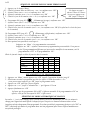
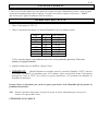
OPERATION OF THE PROOFER
1. Switch "ON" (1).
2. Set the thermostat control and humidity control according to the chart below.
Temp. F
90
95
100
110
RH +/-5% Hum. position
75
4
95
4 1/2
75
4
95
4 1/2
75
4
95
4 1/2
80
4 1/2
90
5
3.If there is too much fog and water drips from the glass doors, adjust humidity control to a lower
number.
4. When the temperature is stabilised, put the products in the proofer.
5. IMPORTANT: When proofing cycle is completed, turn the humidity switch to "OFF" and let the
motor blower and air heat element run for 10-15 minutes to let dry the proofer. Then, turn the main
switch ‘’OFF’’ (0), and leave the door ajar to prevent moulding.
When the proofer is not in operation, open the doors to let out the humidity and to prevent mould.
P.S.
During operation, the doors should not be opened unnecessarily to conserve the heat and humidity
in the proofer.
USE SOFT WATER ONLY.
Cleaning the water pan on top of the proofer periodically can prevent mineral problems.
A-16
OPÉRATION DE L'ÉTUVE / RETARDEUR
1. Programmer la minuterie avant d’ouvrir l’interrupteur principal.
2. Tourner l’interrupteur de mise en marche
3. Sélectionner
pour l’étuve manuel ou
à la position "1".
pour l’étuve retardeur automatique.
4. ‘‘ ‘‘Dans cette position, elle est sur le mode d’étuve. L’unité chauffe jusqu’à ce qu’elle atteigne la
température pré-ajustée (environ 100°F / 37°C), ensuite l’humidité va augmenter jusqu’à ce qu’elle
atteigne le pourcentage d’humidité sélectionné (80% à 85% d’humidité). L’unité de réfrigération ne
peut pas fonctionner en même temps que l’étuve.
‘‘
’’ Dans cette position, vous pouvez programmer la durée que l’unité fonctionnera en mode
d’étuvage et sa durée en mode de réfrigération. Ne soyez inquiet, les deux ne peuvent fonctionner en même
temps! Voir les instructions de programmation de la minuterie.
(Voir les instructions d’opération pour la programmation de la minuterie et les exemples sur les pages suivantes).
ÉTAPE DE LA MINUTERIE :
MINUTERIE ‘ON’ =
MINUTERIE ‘OFF’ =
= DÉMARRAGE du temps d’étuvage
= DÉMARRAGE du temps de réfrigération
NOTE : LE DÉMARRAGE DU TEMPS D’ÉTUVAGE ARRÊTE AUTOMATIQUEMENT LA
RÉFRIGÉRATION.
Bouton
‘ANNULATION’ : Utilisé pour anticiper manuellement l’heure de démarrage de la
prochaine programmation et vice-versa.
5. Ajuster le thermostat à la température désirée (100°F / 37°C)
6. Ajuster l’humidité à la valeur désirée (80%).
7. Ajuster la réfrigération à la température désirée.
**Nous vous suggérons de fermer la lumière quand l’unité est utilisé en mode de réfrigération, car
la lumière crée de la chaleur. De plus, vous sauvez de l’énergie.
8. Recharger l’étuve. Lorsque vous l’utilisez en mode manuel ‘‘ ’’, attendre jusqu’à ce que ‘PREH’
disparaisse du contrôle d’humidité avant de recharger.
Laisser le produit à l’intérieur jusqu’à ce qu’il soit prêt à cuire.
9. Lorsque le cycle d’étuvage est complété, tourner l’interrupteur à ‘‘OFF’’ ou au mode ‘‘AUTO’’.
Lorsque l’étuve n’est pas en opération, ouvrir les portes afin d’évacuer l’humidité et prévenir la
moisissure
P.S. : Les portes ne devraient pas être ouvertes inutilement pour prévenir la chaleur et l’humidité dans
l’étuve
A-17
PROGRAMMATION DE LA MINUTERIE (GRASSLIN DIGI20E-120)
L'agencement circulaire des boutons permet une programmation facile.
Débuter avec Prog pour choisir un programme et ensuite la MAIN
pour sélectionner le chauffage
(ON) ou la réfrigération (OFF) . Poursuivez avec h pour heure et m pour minute et finalement avec Day
pour sélectionner le jour ou les jours de la semaine.
Si une entrée est manquante ou incomplète, le segment manquant clignotera lorsque
ou Prog sera
pressé. Exemple; si "ON" ou "OFF" n'est pas sélectionné, alors le symbole "ON" clignotera.
L'entrée manquante doit être entrée afin de pouvoir mettre le système actif.
Lors de la programmation, si vous pressez h,
paramètres alternent rapidement.
m, ou Day pendant plus de deux secondes, alors les
Un programme consiste à
1. Presser Prog
2. Sélectionner "ON " ou "OFF"
3. Régler heure et minute
4. Régler le ou les jours de fonctionnement (jour individuel ou groupe de jours).
Note: Le programme doit être cohérent, il est donc conseillé d'utiliser Res pour la remise à zéro lors de
toute modification majeure au programme. Ceci afin d'éviter que les différents programmes ne
soient en conflit.
Le clignotement de l'affichage peut indiquer qu'une donnée est manquante ou que le condensateur interne
de maintien d'alimentation de l'appareil est faible (plus de 5 jours).
±1h sert à alterner entre l'heure normale et l'heure avancée (seulement pour les régions qui changent
l'heure).
AJUSTEMENT DE L'HEURE ET DU JOUR.
1.
2.
3.
4.
Sélectionner le cycle de 12:00 heures ou 24 heures.
Presser et maintenir le bouton h et presser ±1h pour basculer d’un cycle à l'autre et de AM et PM.
Presser et maintenir le bouton
Pour les régions qui sont à l'heure avancée, presser ±1h une fois .
5. Régler l'heure en utilisant le bouton h et si AM ou PM n'apparaissent pas, c'est que le cycle est de 24
heures.
6. Régler les minutes en pressant sur le bouton m.
7. Régler la journée de la semaine en pressant sur Day (1 est Lundi et 7 est Dimanche).
8. Relâcher le bouton
A-18
EXEMPLE DE PROGRAMMATION
Lundi au Vendredi
: départ mode étuve à 6:00 Am et arrêt à 8:00 Pm
: départ mode retardeur (réfrigération) à 8:00 Pm et arrêt à 6:00 Am
Dimanche
: départ mode étuve à 7:00 Am et arrêt à 5:00 Pm
: départ mode retardeur (réfrigération) à 5:00 Pm jusqu'au
prochain mode (lundi 6:00Am)
Note: En mode automatique, l'étuve ou le retardeur est en marche, on ne peut pas avoir les deux modes à
l'arrêt en même temps. Quand l'étuve arrête, la réfrigération démarre automatiquement et vice versa.
1. Le jour et la date doivent préalablement avoir été programmés avant d'exécuter ce qui suit. (voir les pages
précédentes)
2. Presser deux fois PROG , vous devriez voir FR=20. Presser
pour retourner à l'affichage de l'heure.
Si vous n'avez pas FR=20 vous devriez presser RES et retourner au numéro #1.Vous devez faire cela pour
éviter qu'un vieux programme interfère avec le nouveau.
3. Presser PROG, vous devriez voir 1234567, sélectionner les jours de la semaine en pesant sur DAY
jusqu'à ce que vous obteniez 123456, pour lundi au vendredi.
4. Sélectionner l'heure (6:00 Am) en pesant sur H (heure) et M (minutes).
5. Presser la MAIN jusqu'à l’obtention de
l'étuve).
dans le bas de l'affichage (pour démarrer le chauffage de
6. Presser PROG, vous devriez voir 1234567, sélectionner les jours de la semaine en pesant sur DAY jusqu'à
l’obtention de 123456.
7. Sélectionner l'heure (8:00 Pm) en pressant H (heure) et M (minute).
8. Presser la MAIN jusqu'à l’obtention de
et démarrer la réfrigération).
dans le bas de l'affichage (pour faire arrêter le chauffage
9. Presser PROG , vous devriez obtenir1234567, sélectionner le jour de la semaine en pressant sur DAY
jusqu'à l’obtention de 7 pour Dimanche.
10. Choisir l'heure (7:00 am) en pesant sur H (heure) et M (minutes).
11. Peser sur la MAIN jusqu'à l’obtention de
sur l'affichage.
12. Presser PROG, vous devriez obtenir 1234567, sélectionner les jours de la semaine en pressant sur DAY
jusqu’à 7.
13. Choisir l'heure (5:00 Pm) en pesant sur H (heure) et M (minutes).
14. Presser la MAIN jusqu'à l’obtention de
15. Presser
sur l'affichage.
A-19
IMPORTANT:
La sortie de la minuterie changera d'état ("ON " ou "OFF") seulement au temps déterminé par la
programmation. Ainsi si la sortie n'est pas à la valeur désirée après avoir terminé la programmation,
elle peut être changée manuellement en utilisant la MAIN
Exemple : vous terminez la programmation à 2:00 PM, la sortie est à "OFF" mais devrait être à "ON" de 8:00
AM à 5:00 PM, alors pressez la MAIN
pour activer temporairement la sortie. L'état de la sortie
sera repris selon la programmation à la prochaine transition , soit à 5:00 PM.
Lorsque
est affiché (mode de fonctionnement normal), il est donc possible de donner une priorité
manuelle temporaire en utilisant le bouton MAIN (Annulation ou "Override"). Cette priorité change pour
l'opposé du mode affiché à chaque fois que l’on presse ce bouton et demeure dans cet état jusqu'au prochain
changement d'état programmé. Il est donc possible de programmer plusieurs cycle "ON" ou OFF" consécutifs
qui ramène le programme dans son état programmé pour contrer l'effet d'annulation sur une période
prolongée.
REVOIR ET CHANGER LE PROGRAMME
Il est possible de revoir le programme à tout moment en pressant le bouton PROG. Vous verrez
successivement, à chaque fois que vous actionnerez la touche PROG, le programme dans l'ordre ou il a été
entré.
Pour modifier le programme il suffit de sélectionner la partie de programme à changer et d'entrer les
nouvelles dates et heures tel que décrit précédemment. Le programme existant est écrasé par les nouvelles
entrées. Presser PROG pour enregistrer les modifications.
Pour effacer un programme individuel, sélectionner le programme comme décrit précédemment et
presser le bouton m et le bouton h jusqu'à l’obtention de "- -" sur l'affichage. Ensuite, presser PROG ou
jusqu'à l’obtention de "- -" qui clignote à l'écran.Ainsi, quelques secondes après le programme sera
effacé.
A-20
PROGRAMMATION DE LA MINUTERIE (GRASSLIN FM1D20E-120)
Ajustement
mode 24hre
ou AM/PM
Affichage du
jour de la
semaine
Opération
manuel ou
Automatique
État de la
minuterie
ON/OFF
Reset
Ajustement pour
changement d’heure
normale ou avancée.
(régions concercées)
Étuvage
Réfrigération
+/- :
(Bouton d’ajustement) En pressant l’un ou l’autre pendant plus de 2 sec. lors de la
programmation, l’unité de temps augmente/diminue de 5 unité à la fois
Menu :
En pressant ce bouton en programmation, vous terminez celle-ci et on retourne en opération
automatique
OK :
Bouton pour confirmer la programmation
Cette minuterie programmable peut être utilisée sous deux modes différents.
1
1. Mode préréglé
2. Mode de programmation personnalisée
2
A-21
MODE PRÉRÉGLÉ
Ce mode comprend 3 programmes. (P01, P02 et P03). Ces programmes ne peuvent être modifiés par
l’utilisateur.
P01
Lundi au Dimanche (1X ON/OFF)
P02
Lundi au Dimanche (2X ON/OFF)
P03
Lundi au Dimanche (3X ON/OFF)
Notez : ‘ON’ = Étuvage et ‘OFF’ = Réfrigération
SÉQUENCE À SUIVRE POUR LE MODE PRÉRÉGLÉ
1.
2.
3.
4.
5.
Appuyer sur le bouton ‘Reset’
Choisir le format 24hre ou PM (avec + ou -) et confirmez avec ‘OK’
Ajustez l’heure (avec + ou -) et confirmez avec ‘OK’
Ajustez les minutes (avec + ou -) et confirmez avec ‘OK’
Choisir le jour de la semaine (avec + ou -) et confirmez avec ‘OK’
Ces étapes servent à
ajuster l’heure. Si l’heure
est correct, appuyer sur
‘OK’ jusqu’à l’étape 6
6. Sélectionnez un des programmes décrit ci-dessus soit, P01, P02 ou P03 (avec + ou -)
7. Deux options sont possible à cette étape-ci :
! Appuyer sur ‘Menu’ = la programmation est terminée
! Appuyer sur ‘OK’ = vous passez en mode de programmation personnalisée
!Ceci ajoute une programmation personnalisée à celle préréglée (Voir en page
suivante pour la programmation personnalisée)
A-22
SÉQUENCE À SUIVRE POUR LE MODE PERSONNALISÉ
1.
2.
3.
4.
5.
Appuyer sur le bouton ‘Menu’
Choisir le format 24hre ou PM (avec + ou -) et confirmez avec ‘OK’
Ajustez l’heure (avec + ou -) et confirmez avec ‘OK’
Ajustez les minutes (avec + ou -) et confirmez avec ‘OK’
Choisir le jour de la semaine (avec + ou -) et confirmez avec ‘OK’
6.
7.
8.
9.
Programme ON (prog 01)
(Démmarage étuvage), confirmez avec ‘OK’
Ajustez l’heure (avec + ou -) et confirmez avec ‘OK’
Ajustez les minutes (avec + ou -) et confirmez avec ‘OK’
Choisir le/les jours de la semaine (avec + ou -) et confirmez avec ‘OK (Voir plus bas les choix de jours
de la semaine)
Ces étapes servent à
ajuster l’heure. Si l’heure
est correct, appuyer sur
‘OK’ jusqu’à l’étape 6
10. Programme OFF (prog 02)
(Démmarage réfrigération), confirmez avec ‘OK’
11. Ajustez l’heure (avec + ou -) et confirmez avec ‘OK’
12. Ajustez les minutes (avec + ou -) et confirmez avec ‘OK’
13. Choisir le/les jours de la semaine (avec + ou -) et confirmez avec ‘OK’
14. Deux options sont possible à cette étape-ci :
! Appuyer sur ‘Menu’ = la programmation est terminée
! Appuyer sur ‘OK’ = ajoutez à nouveau une programmation personnalisée. Vous pouvez
créez 20 programmation différentes qui peuvent être modifiées à tout moment, soit 10
programmation ‘OFF’ et 10 programmation ‘ON’.
Choix de journée simple ou bloc de journée dans la semaine
Lundi
Mardi
Mercredi
Jeudi
Vendredi
Samedi
Dimanche
*
*
*
*
*
*
*
*
-
*
*
*
*
*
*
*
*
*
*
*
*
*
EFFACEMENT D’UNE PROGRAMMATION
1. Appuyter sur ‘Menu’, ensuite appuyer sur ‘OK’ jusqu’à l’apparition du mode ‘prog 01’
2. Sélectionner ensuite le programme qui doit être effacé à l’aide des touches + ou –
(vous pouvez aussi appuyer sur ‘OK’ jusqu’au programme voulu)
3. Appuyer sur ‘OK’ pour que l’heure clignote
4. Appuyer sur + ou – jusqu’à l’obtention de ‘--‘ qui clignote à l’écran
5. Appuyer finalement sur ‘OK’
!À noter que les programmes ON et OFF s’effacent ensemble. Si la programmation ‘ON’ est
effacée, celle qui lui correspond à ‘OFF’ s’efface aussi
SÉLECTION DU MODE AUTOMATIQUE OU MANUEL
La touche ‘+’ sert à interchanger entre le mode manuel (OVR) ou automatique (AUTO). La minuterie
change pour l'opposé du mode affiché à chaque fois que l’on presse ce bouton et demeure dans cet état
jusqu'au prochain changement d'état programmé. Il est donc possible de programmer plusieurs cycle "ON" ou
OFF" consécutifs qui ramène le programme dans son état programmé pour contrer l'effet d'annulation sur
une période prolongée.
A-23
PANNE DE COURANT
L’étuve est sécuritaire même lors d’une panne de courant. Lorsque l’alimentation revient, l’étuve se remet
en marche automatiquement selon le réglage. Il est donc nécessaire de mettre le sélecteur à ‘’ARRÊT’’
afin d’éviter que l’appareil redémarre sans surveillance.
OPÉRATION DE L'ÉTUVE
1. Placer l'interrupteur à "ON" (1).
2. Placer le bouton du thermostat et le bouton d'humidité d’après le tableau suivant
Temp. F
90
95
100
110
RH +/-5% Hum. position
75
4
95
4 1/2
75
4
95
4 1/2
75
4
95
4 1/2
80
4 1/2
90
5
3.S'il y a trop de vapeur, l'eau condensera sur la vitre et des gouttelettes glisseront. Il faut alors
diminuer le réglage d'humidité.
4. Quand la température est stabilisée, charger l'étuve
Quand l'utilisation est terminée, mettre le contrôle d’humidité à "OFF" et laisser
5. IMPORTANT:
fonctionner la chaleur et le ventilateur pour 10-15 minutes. Après cette période, mettre l’interrupteur
principal de l’étuve à "OFF" (0) et laisser les portes entrouvertes. Ceci permettra de minimiser la
formation de moisissure.
Lorsque l’étuve ne fonctionne pas, ouvrir les portes pour laisser sortir l’humidité afin de prévenir la
formation de moisissure.
N.B.
Durant l’opération, bien fermer les portes et ne pas les ouvrir inutilement pour conserver la
chaleur et la vapeur dans l'étuve.
UTILISER DE L’EAU DOUCE..
A-24
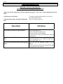
TROUBLESHOOTING
BEFORE CALLING FOR SERVICE
ANSWERS TO MOST FREQUENT QUESTIONS
Always cut off the main power before replacing any parts. Take care of water piping and electric
cable.
Control parts on the front:
Control panel, proofer unit and refrigeration
unit:
Questions
To remove parts from front panels, you have to
go on the top of the unit.
They are located on the top.
Solutions
Check if the light is on.
Check if the proofer switch is on.
Check the breaker of the building.
Check the fuses on the front and in the electrical
control panel.
The blower runs but the unit does not produce Make sure that the thermostat is adjusted to the
desired temperature (over ambient temperature)
heat.
and the pilot light is lit.
The blower runs but the unit does not produce Make sure that the humidity control is set at
about 4.
steam.
Check if you have water in the pan and if the pan
is sit properly on the element.
The unit does not turn on when installed.
A-25
DÉPANNAGE
AVANT D'APPELER LE DÉPARTEMENT DE SERVICE
SOLUTION AUX PROBLÈMES LES PLUS FRÉQUENTS
Toujours fermer l’approvisionnement du courant principal avant le remplacement de pièces. Prendre
garde aux tuyaux de gaz et d’eau avant de déplacer l'étuve.
Les pièces de contrôle à l’avant:
Pour enlever les pièces des panneaux avants, vous
devez aller sur le dessus de l’unité.
Panneau de contrôle, étuve et unité de Elles sont situées sur le dessus.
réfrigération:
Problèmes
Solutions
Vérifier si la lumière est allumée.
Vérifier si l’interrupteur de l’étuve est à la
position "MARCHE".
Vérifier les disjoncteurs du bâtiment.
Vérifier les fusibles à l’avant et dans le panneau
de contrôle électrique.
Le ventilateur fonctionne mais l’unité ne Assurez-vous que le thermostat est ajusté à une
température suffisamment élevée (au dessus de la
produit pas de chaleur.
température ambiante) et que la lampe témoin est
allumée.
Le ventilateur fonctionne mais l’unité ne Assurez-vous que le contrôle d’humidité est
ajusté à environ 4.
produit pas de vapeur.
Vérifier s’il y a de l’eau dans le réservoir et si le
réservoir est correctement placé sur l’élément.
L’étuve ne démarre pas lorsque installée.
A-26
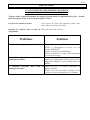
UNIT MAINTENANCE AND CLEANING
Questions
Solutions
Clean the inside of the unit with water and We recommend and sell:
Dirt Buster III: Action foam cleaner
soap.
CHEMCO
Part number: NEB201
Clean the unit exterior with a stainless steel We recommend and sell:
Stainless steel cleaner
cleaner.
SANY or CURTIS (comestible)
Part number : NES201
Clean the water system on the top of the unit. Twice a year clean the water pan and the
immersion element, the water tank if is manual
fill unit and the screen filter.(SEE NEXT PAGE)
Is very important to use distillate water whit the
manual water fill option and a high quality water
filter on automatic water inlet system to prevent
water line obstruction and scale problem in the
water thank.
A-27
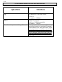
ENTRETIEN ET NETTOYAGE DE L’APPAREIL
Étape par étape
Solutions
Nettoyer l'intérieur de l'étuve avec de l'eau et Produit recommandé:
Dirt Buster III
un détergent.
Nettoyant à four à action moussante
No de pièce: NEB201
Nettoyer l'extérieur de l'étuve avec un produit Produit recommandé:
Nettoyeur pour acier inoxydable
d'entretien pour l'acier inoxydable.
No de pièce: NES201
Nettoyer l’unité d’humidité sur le dessus de Tous les 6 mois, nettoyer l’unité d’évaporation,
vider le compartiment d’eau et le nettoyer avec
l’appareil.
soin. Attention de ne pas endommager
l’interrupteur à niveau d’eau. Nettoyer le filtre à
eau.Utiliser de l’eau distillée dans le système de
remplissage manuel et une eau de haute qualité
dans celui à remplissage automatique. Ceci dans
le but d’éviter des problèmes (obstruction) au
niveau du compartiemnt d’eau.
A-28
A-28
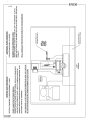
MAINTENANCE: WATER COMPARTMENT
ENTRETIEN: UNITÉ D’ÉVAPORATION
SECTION B:
COMPONENT PARTS / PIÈCES COMPOSANTES
B-2
B-2
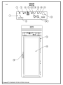
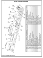
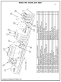
ER136 FRONT VIEW
ER136 VUE DE FACE
B-3
Item
Part Number
1
2
3
4
5
6
7
8
9
10
11
12
ET103
RFTH10
ELI655
ELM680
ELI650
ELT628
ELT620
ELT627
ELL650
ELI640
ELB096
RFTH05
13
ELT610C
14
15
16
QUP320
P2969R
QUP520
Item
Num. Pièce
1
2
3
4
5
6
7
8
9
10
11
12
ET103
RFTH10
ELI655
ELM680
ELI650
ELT628
ELT620
ELT627
ELL650
ELI640
ELB096
RFTH05
13
ELT610C
14
15
16
QUP320
P2969R
QUP520
Description
DECAL RETARDER
THERMOMETER COOPER -40 TO 120°F
MINIATURE SWITCH SPDT IDEAL 774013
GRASSLIN PROGRAMMABLE TIMER FOR RETARDER PROOFER
MINIATURE SWITCH SPST 20A IDEAL 774011
THERMOSTAT KNOB 110°F
THERMOSTAT BEZEL
THERMOSTAT 110°F
RED PILOT LIGHT 250V
MINIATURE SWITCH DPST BP9
5A BREAKER
THERMOMETER 40-240°F
HUMIDITY THERRMOSTAT ELT610 (G1-11712) FOR E & ER PROOFER
SERIAL # 5000 WITH KNOB ELT612
DOOR HINGE
RETARDER PROOFER DOOR
MAGNETIC HANDLE
Description
LEXAN ÉTUVE RETARDEUR 33.000" X 8.250"
THERMOSTAT DE RÉFRIGÉRATION A19-ABC-24
INTERRUPTEUR - MINIATURE IDEAL 774013
MINUTERIE PROGRAMMABLE GRASSLIN (ÉTUVE RETARDEUR)
INTERRUPTEUR - MINIATURE SPST 20A IDEAL 774011
BOUTON DE THERMOSTAT 110°F
PLAQUE DE THERMOSTAT
THERMOSTAT 110°F
LAMPE TÉMOIN ROUGE 250 V
INTERRUPTEUR - MINIATURE DPST BP9
DISJONCTEUR 5A
THERMOMÈTRE 40-240°F
THERMOSTAT D'HUMIDITÉ ELT610 (G1-11712) POUR ÉTUVE E & ER #
SÉRIE 5000 AVEC BOUTON ELT612
PENTURE DE PORTE
PORTE D'ÉTUVE RETARDEUR
POIGNÉE MAGNÉTIQUE
Quantity
1
1
1
1
1
1
2
1
3
1
1
1
1
4
1
1
Quantité
1
1
1
1
1
1
2
1
3
1
1
1
1
4
1
1
B-4
B-4
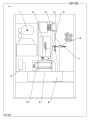
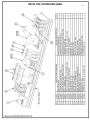
ER136 TOP VIEW
ER136 VUE DE DESSUS
B-5
Item
1
2
OR
3
OR
Part Number
RFC010
ELE166
ELE167
ELE133
ELE134
4
ELS887
OR
ELS888
AND
5
6
7
8
OR
9
AND
10
11
ELS889
QUF350
PLF100
ELV590
P240SER1
P220SER1
ELF660
ELF650
ELM731
RFPS10
Item
1
2
OU
3
OU
4
Numéro Pièce
RFC010
ELE166
ELE167
ELE133
ELE134
OU
ET
5
6
7
8
OU
9
ET
10
11
ELS887
ELS888
ELS889
QUF350
PLF100
ELV590
P240SER1
P220SER1
ELF660
ELF650
ELM731
RFPS10
Description
REFRIGERATION UNIT 1/3 HP
IMMERSION ELEMENT 208V 1500W
IMMERSION ELEMENT 240V 1500W
COIL ELEMENT 208V 4000W
COIL ELEMENT 240V 4000W
SOLENOID VALVE WITH DIN CONNECTION 110/120V
50/60HZ
SOLENOID VALVE WITH DIN CONNECTION 220/240V
50/60HZ
JUNCTION BOX FOR ELS887 & ELS888
ELECTRIC FLOAT
WATER FILTER
NEEDLE VALVE
ER136 CONTROL PANEL 208V OR 240V 1 PH
ER136 CONTROL PANEL 220V 1 PH
VAPOR TYPE FIXTURE
PLASTIC BULB PROTECTOR
MOTOR BLOWER 115 CFM
DUAL PRESSURE CONTROL
Quantity
1
1
1
1
1
Description
UNITE DE REFRIGERATION 1/3Hp
ÉLÉMENT IMMERSION 208V 1500W
ÉLÉMENT IMMERSION 240V 1500W
ÉLÉMENT BOUDIN 208V 4000W
ÉLÉMENT BOUDIN 240V 4000W
VALVE À SOLENOÏDE AVEC CONNECTION DIN 110/120V
50/60HZ
VALVE À SOLENOÏDE AVEC CONNECTION DIN 220/240V
50/60HZ
BOÎTE DE JONCTION POUR ELS887 & ELS888
INTERRUPTEUR À NIVEAU D'EAU
FILTRE À EAU
VALVE À POINTEAU
PANNEAU ÉLECTRIQUE ER136 208V OU 240V 1 PH
PANNEAU ÉLECTRIQUE ER136 220V 1 PH
FIXATION DE LUMIERE ETANCHE
PROTECTEUR DE PLASTIQUE POUR LUMIERE
VENTILATEUR 115 CFM
CONTROL DE PRESSION DOUBLE
Quantité
1
1
1
1
1
1
1
1
1
1
1
1
1
1
1
1
1
1
1
1
1
1
1
1
1
1
1
1
1
B-6
B-6
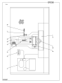
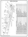
ER236 TOP VIEW
ER236 VUE DE DESSUS
B-7
Item
1
2
3
OR
4
OR
5
Part Number
RFC020
RFPS10
ELE168
ELE169
ELE134
ELE133
QUF350
6
ELS887
OR
ELS888
AND ELS889
7
PLF100
8
ELV590
9
ELM731
10
ELF660
AND ELF650
AND ELA275
11
P240SER1
OR P220SER1
Item
1
2
3
OU
4
OU
5
Numéro Pièce
RFPS10
ELE168
ELE169
ELE134
ELE133
QUF350
6
ELS887
OU
ELS888
ET
7
8
9
10
ET
ET
11
OU
ELS889
PLF100
ELV590
ELM731
ELF660
ELF650
ELA275
P240SER1
P220SER1
Description
REFRIGERATION UNIT 1/2Hp
DUAL PRESSURE CONTROL
IMMERSION ELEMENT 240V 3000W
IMMERSION ELEMENT 208V 3000W
COIL ELEMENT 240V 4000W
COIL ELEMENT 208V 4000W
ELECTRIC FLOAT
SOLENOID VALVE WITH DIN CONNECTION 110/120V
50/60HZ
SOLENOID VALVE WITH DIN CONNECTION 220/240V
50/60HZ
JUNCTION BOX FOR ELS887 & ELS888
WATER FILTER
NEEDLE VALVE
MOTOR BLOWER 115 CFM
VAPOR TYPE FIXTURE
PLASTIC BULB PROTECTOR
BULB 60W 130V
ER136 CONTROL PANEL 208V OR 240V 1 PH
ER136 CONTROL PANEL 220V 1 PH
Quantity
1
1
1
1
1
1
1
Description
UNITE DE REFRIGERATION 1/2Hp
CONTROL DE PRESSION DOUBLE
ÉLÉMENT IMMERSION 240V 3000W
ÉLÉMENT IMMERSION 208V 3000W
ÉLÉMENT BOUDIN 240V 4000W
ÉLÉMENT BOUDIN 208V 4000W
INTERRUPTEUR À NIVEAU D'EAU
VALVE À SOLENOÏDE AVEC CONNECTION DIN
110/120V 50/60HZ
VALVE À SOLENOÏDE AVEC CONNECTION DIN
220/240V 50/60HZ
BOÎTE DE JONCTION POUR ELS887 & ELS888
FILTRE À EAU
VALVE À POINTEAU
VENTILATEUR 115 CFM
FIXATION DE LUMIERE ETANCHE
PROTECTEUR DE PLASTIQUE POUR LUMIERE
AMPOULE INCANDESCENTE 60W 130V
PANNEAU ÉLECTRIQUE ER136 208V OU 240V 1 PH
PANNEAU ÉLECTRIQUE ER136 220V 1 PH
Quantité
1
1
1
1
1
1
1
1
1
1
1
1
1
1
1
1
1
1
1
1
1
1
1
1
1
1
1
1
1
SECTION C:
CONTROL PANELS / PANNEAUX DE CONTRÔLE
C-2
C-2
ER136 1PH 220V 60HZ
ER136 1PH 220V 60HZ
C-3
C-3
ER136 1PH 208 - 240V 60HZ
ER136 1PH 208 - 240V 60HZ
C-4
C-4
ER236 1PH 220V 50HZ
ER236 1PH 220V 50HZ
C-5
ER236 1PH 208 - 240 60HZ
ER236 1PH 208 - 240 60HZ
C-5
WARRANTY
/
GARANTIE
LIMITED WARRANTY
(Continental United States Of America And Canada Only)
Doyon Equipment Inc. guarantees to the original purchaser only that its product are
free of defects in material and workmanship, under normal use.
This warranty does not cover any light bulbs, thermostat calibration or defects due to
or resulting from handling, abuse, misuse, nor shall it extend to any unit from which
the serial number has been removed or altered, or modifications made by
unauthorised service personnel or damage by flood, fire or other acts of God. Nor will
this warranty apply as regards to the immersion element damaged by hard water.
The extent of the manufacturer’s obligation under this warranty shall be limited to the
replacement or repair of defective parts within the warranty period. The decision of
the acceptance of the warranty will be made by Doyon Equipment service
department, which decision will be final.
The purchaser is responsible for having the equipment properly installed, operated
under normal conditions with proper supervision and to perform periodic preventive
maintenance.
If any parts are proven defective during the period of one year from date of purchase,
Doyon Equipment Inc. hereby guarantees to replace, without charge, F.O.B. Linière,
Quebec, Canada, such part or parts.
Doyon Equipment Inc will pay the reasonable labour charges in connection with the
replacement parts occurring within one year from purchase date. Travel over 50
miles, holiday or overtime charges are not covered. After one year from purchase
date, all labour and transportation charges in connection with replacement parts will
be the purchaser’s responsibility.
Doyon Equipment Inc. does hereby exclude and shall not be liable to purchaser for
any consequential or incidental damages including, but not limited to, damages to
property, damages for loss of use, loss of time, loss of profits or income, resulting
from any breach or warranty.
In no case, shall this warranty apply outside Canada and continental United States
unless the purchaser has a written agreement from Doyon Equipment Inc.
GARANTIE LIMITÉE
(Pour le Canada et les États continentaux des États-Unis)
Équipement Doyon Inc. garantit ses produits à l'acheteur original, contre tout défaut
de matériaux ou de fabrication, en autant qu'ils aient été utilisés de façon normale.
Cette garantie ne s'applique cependant pas sur les ampoules, les calibrations de
température, tout défaut dû ou résultant d'une mauvaise manipulation, d'un emploi
abusif ou d'un mauvais usage. La garantie ne s'applique pas non plus sur tout
équipement dont le numéro de série aurait été enlevé ou altéré, tout produit modifié
par du personnel de service non autorisé, endommagé par une inondation, un feu ou
tout autre acte de Dieu, ni sur les éléments immergés endommagés par l'eau dure.
L'étendue des obligations du manufacturier, selon cette garantie, est le remplacement
ou la réparation des pièces défectueuses durant la période de garantie. L'acceptation
de la garantie sera faite par le département de service d'Équipement Doyon Inc.
Cette décision sera définitive.
L'acheteur est responsable de faire installer son équipement adéquatement, de
l'opérer sous des conditions normales d'utilisation avec une bonne supervision, ainsi
que d'effectuer un entretien préventif périodique.
Dans le cas où les pièces s'avéreraient défectueuses durant une période d'un an à
partir de la date d'achat, Équipement Doyon Inc. s'engage à les remplacer, sans
frais, F.O.B. Linière, Québec, Canada.
Équipement Doyon Inc. couvrira les frais raisonnables de main-d'œuvre reliés au
remplacement des pièces, pour une période d'un an à partir de la date d'achat.
Toutefois, les frais encourus pour les déplacements au-delà de 50 milles, le temps
supplémentaire et les jours de congé ne sont pas couverts. Au-delà d'un an après la
date d'achat, tous frais de transport et de main-d'œuvre pour le remplacement des
pièces sont la responsabilité de l'acheteur.
Équipement Doyon Inc. ne se tient pas responsable envers l'acheteur pour toutes
conséquences ou dommages incluant, mais non limités à, dommages à la propriété,
dommages pour perte d'usage, perte de temps, perte de profits ou de revenus,
provenant de tout bris de garantie.
En aucun cas, cette garantie ne s'applique à l'extérieur du continent des États-Unis
d'Amérique ou du Canada, à moins que l'acheteur n'ait une entente écrite avec
Équipement Doyon Inc.
ÉQUIPEMENT DOYON INC.
1255, rue Principale
Linière, Qc, Canada G0M 1J0
Tel.: 1 (418) 685-3431
Canada: 1 (800) 463-1636
US: 1 (800) 463-4273
FAX: 1 (418) 685-3948
Internet: http://www.doyon.qc.ca
e-mail: [email protected]