1
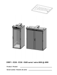
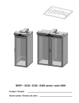
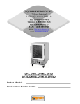
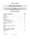
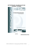
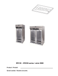
DP14 - DP14A
Product / Produit:
Serial number / Numéro de série:
IMPORTANT SAFETY INSTRUCTIONS
SAVE THESE INSTRUCTIONS
DANGER
TO REDUCE THE RISK OF FIRE OR ELECTRIC SHOCK
CAREFULLY FOLLOW THESE INSTRUCTIONS
TABLE OF CONTENTS
(table des matières :page suivante)
Description ___________________________________________________________________ A-1
Introduction________________________________________________________________ A-2
Construction _______________________________________________________________ A-2
Shipping __________________________________________________________________ A-2
Installation warnings_________________________________________________________ A-4
Distances to respect__________________________________________________________ A-4
Installation ________________________________________________________________ A-6
Operation _________________________________________________________________ A-8
Troubleshooting ___________________________________________________________ A-10
Oven maintenance and cleaning _______________________________________________ A-12
Component parts ________________________________________________________________B-1
DP14 - Front view ____________________________________________________________B-2
DP14 - Top view _____________________________________________________________B-4
DP14A - Front view___________________________________________________________B-6
DP14A - Top view____________________________________________________________B-8
Control Panels__________________________________________________________________C-1
DP14 1PH 120V 60HZ ________________________________________________________C-2
DP14 1PH 120V/208V 120V/240V 60HZ__________________________________________C-3
DP14 1PH 208-220-240V 50/60HZ_______________________________________________C-4
DP14 1PH 120V 60HZ AUTO __________________________________________________C-5
DP14 1PH 120V/208V 120V/240V 60HZ AUTO ____________________________________C-6
DP14 1PH 208-220-240V 50/60HZ AUTO_________________________________________C-7
Warranty ________________________________________________________________________1
DP14 [LIVRET].doc
09/2008
IMPORTANT INSTRUCTIONS DE SÉCURITÉ
CONSERVEZ CE MANUEL D’INSTRUCTIONS
DANGER
AFIN DE RÉDUIRE LES RISQUES D'INCENDIE OU D'ÉLECTROCUTION
SUIVRE CES INSTRUCTIONS AVEC SOIN
TABLE DES MATIÈRES
Description ____________________________________________________________________A-1
Introduction ________________________________________________________________A-3
Construction ________________________________________________________________A-3
Expédition __________________________________________________________________A-3
Avertissement lors de l'installation_______________________________________________A-5
Distances à respecter _________________________________________________________A-5
Installation _________________________________________________________________A-7
Opération __________________________________________________________________A-9
Dépannage ________________________________________________________________A-11
Entretien et nettoyage du four__________________________________________________A-13
Pièces composantes _____________________________________________________________B-1
DP14 - Vue de face ___________________________________________________________B-2
DP14 - Vue de dessus _________________________________________________________B-4
DP14A - Vue de face __________________________________________________________B-6
DP14A - Vue de dessus ________________________________________________________B-8
Panneaux de contrôle ____________________________________________________________C-1
DP14 1PH 120V 60HZ ________________________________________________________C-2
DP14 1PH 120V/208V 120V/240V 60HZ __________________________________________C-3
DP14 1PH 208-220-240V 50/60HZ _______________________________________________C-4
DP14 1PH 120V 60HZ AUTO ___________________________________________________C-5
DP14 1PH 120V/208V 120V/240V 60HZ AUTO _____________________________________C-6
DP14 1PH 208-220-240V 50/60HZ AUTO _________________________________________C-7
Garantie ________________________________________________________________________1
DP14 [LIVRET].doc
09/2008
SECTION A:
DESCRIPTION
/
DESCRIPTION
A-2
CAUTION
The manufacturer suggests to read this manual carefully.
INTRODUCTION
This equipment is manufactured with first quality material by experienced technicians.
installation and maintenance will guarantee a reliable service for years to come.
Proper
A nameplate fixed to the front of the proofer specifies the serial number, model number, number of
phase, amperage, voltage and frequency.
Drawings and replacement part numbers are included in this manual. The electrical diagram is affixed
in the control panel located on the top of the proofer.
ATTENTION
DOYON is not responsible for damages to the property or the equipment caused
by personnel who is not certified by known organisations. The customer is
responsible for finding qualified technicians in electricity and plumbing for the
installation of the oven.
CONSTRUCTION
You just bought the most advanced proofer in the world, the "DOYON" technology at its best. This
proofer is manufactured using the highest quality components and material.
The DOYON equipments are designed with parts that are easy to find.
SHIPPING
For your safety, this equipment has been verified by qualified technicians and carefully crated before
shipment. The freight company assumes full responsibility concerning the delivery in good condition of
the equipment in accepting to transport it.
IMPORTANT
RECEPTION OF THE MERCHANDISE
Take care to verify that the received equipment is not damaged before signing the delivery receipt. If a
damage or a lost part is noticed, write it clearly on the receipt. If it is noticed after the carrier has left,
contact immediately the freight company in order that they do their inspection.
We do not assume the responsibility for damages or losses that may occur during transportation.
A-3
ATTENTION
Le manufacturier suggère de lire ce manuel attentivement et de suivre avec soin les instructions
fournies.
INTRODUCTION
Votre équipement est fabriqué avec des matériaux de première qualité par des techniciens
d'expérience. Une utilisation normale et un entretien adéquat de l'équipement vous assureront
plusieurs années de bon service.
Une plaque signalétique, située à l’avant de l’étuve, mentionne le numéro de série, le numéro du
modèle, le nombre de phases, l’ampérage, le voltage et la fréquence.
Les dessins et les numéros de pièces de rechange sont inclus dans ce manuel. Le plan électrique est
affiché dans la boîte de contrôle sur le dessus de l’étuve.
ATTENTION
Équipement Doyon Inc. ne peut être tenu responsable pour les dommages causés à
la propriété ou à l'équipement par du personnel non certifié par des organismes
accrédités. Le client a la responsabilité de retenir les services d'un technicien
spécialisé en électricité et d'un plombier qualifié pour l'installation de l'étuve.
CONSTRUCTION
Vous avez maintenant en votre possession l’étuve la plus performante présentement disponible sur le
marché, une étuve utilisant la technologie "Doyon" à son meilleur. Cette étuve est fabriquée avec des
matériaux de première qualité.
L’étuve DOYON est fabriquée avec des matériaux et pièces composantes facilement disponibles sur le
marché.
EXPÉDITION
Pour votre protection, cet équipement a été vérifié et emballé avec précaution par des techniciens
qualifiés avant son expédition. La compagnie de transport assume la pleine responsabilité
concernant la livraison de cet équipement en bon état en acceptant de le transporter.
IMPORTANT
RÉCEPTION DE LA MARCHANDISE
Avant de signer le reçu de livraison, prenez soin de vérifier dès la réception si l'équipement n'est pas
endommagé. Si un dommage ou une perte est détecté, écrivez-le clairement sur le reçu de livraison
ou votre bon de transport et faites signer le livreur. Si le dommage est remarqué après le départ du
transporteur, contactez immédiatement la compagnie de transport afin de leur permettre de
constater les dommages causés.
Nous ne pouvons assumer la responsabilité pour les dommages ou les pertes qui pourraient survenir
pendant le transport.
A-4
INSTALLATION WARNINGS
FOR YOUR SAFETY
DO NOT STORE OR USE GASOLINE OR OTHER FLAMMABLE VAPORS
AND LIQUIDS IN THE VICINITY OF THIS OR ANY APPLIANCE.
IMPORTANT
INSTALLATION AND SERVICE
Installation and service must be done by specialized technicians. Contact a certified electrician and
plumber for set up.
The proofer must be connected to the utility and electrically grounded in conformity to the effective
local regulations. If these are not established, the oven must be connected according to the Canadian
Electrical Code (CSA-C22.1-XX) or National Electrical Code (NFPA 70-XX). Refer to last edition
year for XX.
DISTANCES TO RESPECT
●
Top of the proofer: a clearance of 12 inches to the ceiling must exist to permit maintenance.
●
Back and sides:0 inch clearance.
A-5
AVERTISSEMENT LORS DE L'INSTALLATION
POUR VOTRE SÉCURITÉ
NE PAS EMMAGASINER OU UTILISER D'ESSENCE OU AUTRES VAPEURS
ET LIQUIDES INFLAMMABLES À PROXIMITÉ DE CET ÉQUIPEMENT
OU DE TOUT AUTRE APPAREIL.
IMPORTANT
INSTALLATION ET SERVICE
L'installation et le service doivent être faits par un technicien spécialisé. Contactez un technicien
spécialisé en électricité pour l'installation d’une prise de courant adéquate.
Cet appareil doit être branché et mis à la terre (grounded) conformément aux règlements effectifs de
votre localité. Si aucune réglementation n'est établie, l’appareil doit être branché conformément au
Code Canadien de l’électricité CSA 22.1-XX ou au Code National de l'Électricité NFPA 70-XX.
Référez vous à l’année de la dernière édition pour XX.
DISTANCES À RESPECTER
●
Dessus de l'étuve : Il est obligatoire d’avoir au moins 12 pouces entre le dessus de l’étuve et le
plafond afin d’effectuer le service.
●
Arrière et côtés de l'étuve :Aucun espace nécessaire.
A-6
INSTALLATION
IN GENERAL
Take off the packaging material with care.
accessories.
Take off all the material used for packing and
Each unit is set up to be used with the electrical supply specified on the nameplate fixed on the front
of the unit.
If the equipment is delivered with casters , always LOCK the wheels after installation and use a
flexible wire.
1. To the electrician
Electrical supply installation must be in accordance with the electrical rating on the nameplate and
use flexible wire.
2. To the plumber
MANUAL WATER FILL
No water line is required. Water is filled manually in the pan inside the proofer.
This equipment is to be installed to comply with the applicable federal, state or local plumbing
codes.
Connect the steam system (1/4 NPT) to the cold water distribution network.
We highly recommend a water softener to eliminate minerals in the water.
We suggest to use CUNO # CFS6135 (Doyon part number PLF240).
A-7
INSTALLATION
EN GÉNÉRAL
Ouvrir avec soin l'emballage de votre équipement. Enlever tous les matériaux utilisés pour
l'envelopper ainsi que les accessoires.
Chaque unité est fabriquée pour être utilisée avec la source électrique spécifiés sur la plaque
signalétique de l’appareil.
Si l’appareil est muni de roulettes,veuillez toujours les BLOQUER après l’installation et utiliser un
cordon souple.
1. À l'électricien
L’installation de l’alimentation électrique des fours doit être conforme avec la source électrique
spécifiée sur la plaque signalétique et vous devez utiliser un conduit flexible approprié.
2. Au plombier
REMPLISSAGE MANUEL DU RÉSERVOIR D'EAU
Aucune ligne d’eau n’est requise. Le réservoir d’eau à l’intérieur de l’étuve est rempli
manuellement.
Relier le système de vapeur (1/4 NPT) au réseau de distribution d’eau.
Il est fortement recommandé d’installer un adoucisseur d’eau à l’entrée de l’appareil afin
d’éliminer les minéraux dans l’eau.
Nous recommandons la marque CUNO #CFS6135 (numéro de pièce Doyon PLF240).
A-8
OPERATION
1. Switch "ON".
2. Set the thermostat control at 100° F.
3. Fill water pan if not automatic and set the humidity control at 4.
If there is too much fog and water drips from the glass doors, adjust humidity control to a lower
number.
4. When the temperature is stabilized, put the products in the proofer.
(Leave them inside until they are ready to bake.)
5. When proofing cycle is completed, turn the switch "OFF".
When the proofer is not in operation, open the doors to let out the humidity and to prevent
mould.
P.S.
The doors should not be opened unnecessarily to conserve the heat and humidity in the
proofer.
Every day cleaning of the water pan under the proofer's doors should be exercised.
POWER FAILURE
When the power comes back, the proofer will start automatically. Then it is recommended to turn
off the unit to avoid it starting without supervision.
A-9
OPÉRATION
1. Placer l'interrupteur à "ON".
2. Placer le bouton du thermostat à 100°F.
3. Remplir le réservoir d’eau si ce n’est pas automatique et régler le contrôle d’humidité à 4.
S’il y a trop de vapeur, l’eau condensera sur la vitre et des gouttelettes glisseront. Il faut alors
diminuer le réglage d’humidité.
4. Quand la température est stabilisée, charger l’étuve.
(Laisser le produit à l’intérieur jusqu’à ce qu’il soit prêt à cuire.)
5. Lorsque le cycle d’étuvage est complété, placer l’interrupteur à "OFF".
Lorsque l’étuve ne fonctionne pas, ouvrir les portes pour laisser sortir l’humidité afin de prévenir
la formation de moisissure.
N.B.
Bien fermer les portes et ne pas les ouvrir inutilement pour conserver la chaleur et la vapeur
dans l'étuve.
Bien nettoyer à tous les jours le récupérateur d'eau situé en dessous de la porte.
PANNE DE COURANT
Au retour du courant, l’étuve se remet en marche automatiquement. Il est donc nécessaire de mettre
le sélecteur à "ARRËT" afin d’éviter que l’étuve ne redémarre sans surveillance.
A-10
TROUBLESHOOTING
BEFORE CALLING FOR SERVICE
ANSWERS TO MOST FREQUENT QUESTIONS
Always cut off the main power before replacing any parts. Take care of water piping and
electric cable.
Control parts on the front:
Control panel, proofer unit and refrigeration
unit:
Questions
To remove parts from front panels, you have to
go on the top of the unit.
They are located on the top.
Solutions
Check if the light is on.
Check if the proofer switch is on.
Check the breaker of the building.
Check the fuses on the front and in the electrical
control panel.
The blower runs but the unit does not produce Make sure that the thermostat is adjusted to the
desired temperature (over ambient temperature)
heat.
and the pilot light is lit.
The blower runs but the unit does not produce Make sure that the humidity control is set at
about 4.
steam.
Check if you have water in the pan and if the pan
is sit properly on the element.
The unit does not turn on when installed.
A-11
DÉPANNAGE
AVANT D'APPELER LE DÉPARTEMENT DE SERVICE
SOLUTION AUX PROBLÈMES LES PLUS FRÉQUENTS
Toujours fermer l’approvisionnement du courant principal avant le remplacement de pièces.
Prendre garde aux tuyaux de gaz et d’eau avant de déplacer l'étuve.
Les pièces de contrôle à l’avant:
Pour enlever les pièces des panneaux avants, vous
devez aller sur le dessus de l’unité.
Panneau de contrôle, étuve et unité de Elles sont situées sur le dessus.
réfrigération:
Problèmes
Solutions
Vérifier si la lumière est allumée.
Vérifier si l’interrupteur de l’étuve est à la
position "MARCHE".
Vérifier les disjoncteurs du bâtiment.
Vérifier les fusibles à l’avant et dans le panneau
de contrôle électrique.
Le ventilateur fonctionne mais l’unité ne Assurez-vous que le thermostat est ajusté à une
température suffisamment élevée (au dessus de la
produit pas de chaleur.
température ambiante) et que la lampe témoin est
allumée.
Le ventilateur fonctionne mais l’unité ne Assurez-vous que le contrôle d’humidité est
ajusté à environ 4.
produit pas de vapeur.
Vérifier s’il y a de l’eau dans le réservoir et si le
réservoir est correctement placé sur l’élément.
L’étuve ne démarre pas lorsque installée.
A-12
OVEN MAINTENANCE AND CLEANING
Questions
Solutions
Clean the inside of the unit with water and We recommend and sell:
Dirt Buster III: Action foam cleaner
soap.
CHEMCO
Part number: NEB201
Clean the unit exterior with a stainless steel We recommend and sell:
Stainless steel cleaner
cleaner.
SANY or CURTIS (comestible)
Part number : NES201
CAUTION
Save these instructions.
A-13
ENTRETIEN ET NETTOYAGE DU FOUR
Étape par étape
Solutions
Nettoyer l'intérieur de l'étuve avec de l'eau et Produit recommandé:
Dirt Buster III
un détergent.
Nettoyant à four à action moussante
No de pièce: NEB201
Nettoyer l'extérieur de l'étuve avec un produit Produit recommandé:
Nettoyeur pour acier inoxydable
d'entretien pour l'acier inoxydable.
No de pièce: NES201
ATTENTION
Conserver ces instructions.
SECTION B:
COMPONENT PARTS / PIÈCES COMPOSANTES
B-2
DP14 - FRONT
VIEW
DP14
DP14 - VUE DE FACE
B-2
VUE DE FACE/FRONT VIEW
3 4 5
6
1
7 8 9
10 11
12
2
13
14
15
17 18 19
16
21
G:\ACAD10\ETUVE\MANUEL\DP14 FACE.dft
20
B-3
Item
1
2
3
4
5
6
7
8
9
10
11
12
13
14
15
16
17
18
19
20
21
Part Number
Description
P1555EG
LEFT DOOR DP14 (55 3/16" X 15 7/16")
QUP320
DOOR HINGE
ELT628
THERMOSTAT KNOB 110°F
ELT620
THERMOSTAT BEZEL
ELT627
THERMOSTAT 110°F
ELL650
RED PILOT LIGHT 250V
ELI240
INFINITY SWITCH KNOB
ELI220
HUMIDITY CONTROL 120V
ELI230
HUMIDITY CONTROL 240V
ELI402
BLACK SELECTOR 2 POS.
ELI406
BASE WITH 1NO
ELB098
2A BREAKER
QUA200
DOOR MAGNET
P1555ED
RIGHT DOOR DP14 (55 3/16" X 15 7/16")
QUP465
STAIN. STEEL TUBULAR HANDLE FOR DOOR
ETUVE_0924
14 SHELVES SIDERACK
REEF10
WATER PAN FOR PROOFER 13 X 14 X 2 1/2
ELE127F01 FORMED ELEMENT FOR DP14 (MANUAL) 120V 1250 W
ELE124F03 FORMED ELEMENT 240V 1250 W FOR DP14 (MANUAL)
PAR850
SWIVEL CASTER WITH BRAKE
PAR800
SWIVEL CASTER
Quantity
1
4
1
1
1
2
1
1
1
1
1
1
4
1
2
2
1
1
1
2
1
Item
1
2
3
4
5
6
7
8
9
10
11
12
13
14
15
16
17
18
19
20
21
Numéro Pièce
P1555EG
QUP320
ELT628
ELT620
ELT627
ELL650
ELI240
ELI220
ELI230
ELI402
ELI406
ELB098
QUA200
P1555ED
QUP465
ETUVE_0924
REEF10
ELE127F01
ELE124F03
PAR850
PAR800
Quantité
1
4
1
1
1
2
1
1
1
1
1
1
4
1
2
2
1
1
1
2
1
Description
PORTE GAUCHE DP14 (55 3/16" X 15 7/16")
PENTURE DE PORTE
BOUTON DE THERMOSTAT 110°F
PLAQUE DE THERMOSTAT
THERMOSTAT 110°F
LAMPE TEMOIN ROUGE 250 V
BOUTON DE CONTRÔLE D'HUMIDITÉ
CONTRÔLEUR D'HUMIDITÉ 120V
CONTRÔLEUR D'HUMIDITÉ 240V
SÉLECTEUR 2 POS. NOIR
BASE AVEC 1NO
DISJONCTEUR 2A
AIMANT DE PORTE
PORTE DROITE DP14 (55 3/16" X 15 7/16")
POIGNÉE DE PORTE TUBULAIRE (ACIER INOX.)
SUPPORT LATÉRAL 14 TABLETTES
PLAT D'EAU POUR ÉTUVE 13 X 14 X 2 1/2
ÉLÉMENT FORMÉ 120V 1250 W POUR DP14 (MANUEL)
ÉLÉMENT FORMÉ 240V 1250 W POUR DP14 (MANUEL)
ROULETTE PIVOTANTE AVEC FREIN
ROULETTE PIVOTANTE
B-4
B-4
DP14 - DP14
TOP VIEW
DP14 - VUE DE DESSUS
VUE DE DESSUS/TOP VIEW
1 2
6
3
4
5
7
10
G:\ACAD10\ETUVE\MANUEL\DP14 DESSUS.dft
9
8
B-5
Item
1
2
3
4
5
6
7
8
9
10
Part Number
ELA275
ELF650
ELE130
ELE131
ELE132
ELT505
ELM731
ELB071
ELL050
ELC860
Description
BULB 60W 130V
BULB PROTECTOR
COIL ELEMENT 120V 1500W
COIL ELEMENT 208V 1500W
COIL ELEMENT 240V 1500W
THERMODISK 300°F
MOTOR BLOWER 115 CFM
CONNECTOR BLOCK 2P 175A
GROUND LUG
CONTACTOR 2P 30A 110V
Quantity
1
1
1
1
1
1
1
1
1
1
Item
1
2
3
4
5
6
7
8
9
10
Numéro Pièce
ELA275
ELF650
ELE130
ELE131
ELE132
ELT505
ELM731
ELB071
ELL050
ELC860
Description
AMPOULE INCANDESCENTE 60W 130V
PROTECTEUR D'AMPOULE
ÉLÉMENT BOUDIN 120V 1500W
ÉLÉMENT BOUDIN 208V 1500W
ÉLÉMENT BOUDIN 240V 1500W
THERMODISQUE 300°F
VENTILATEUR 115 CFM
BORNIER 2P 175A
TERMINAL DE MISE À LA TERRE
CONTACTEUR 2P 30A 110V
Quantité
1
1
1
1
1
1
1
1
1
1
B-6
DP14A -DP14A
FRONT VIEW
DP14A - VUE DE FACE
B-6
VUE DE FACE/FRONT VIEW
3 4 5
6
1
7 8 9
10 11
12
2
13
14
15
16
21
G:\ACAD10\ETUVE\MANUEL\DP14A FACE.dft
20
B-7
Item
1
2
3
4
5
6
7
8
9
10
11
12
13
14
15
16
20
21
Part Number
P1555EG
QUP320
ELT628
ELT620
ELT627
ELL650
ELI240
ELI220
ELI230
ELI402
ELI406
ELB098
QUA200
P1555ED
QUP465
ETUVE_0924
PAR850
PAR800
Description
LEFT DOOR DP14 (55 3/16" X 15 7/16")
DOOR HINGE
THERMOSTAT KNOB 110°F
THERMOSTAT BEZEL
THERMOSTAT 110°F
RED PILOT LIGHT 250V
INFINITY SWITCH KNOB
HUMIDITY CONTROL 120V
HUMIDITY CONTROL 240V
BLACK SELECTOR 2 POS.
BASE WITH 1NO
2A BREAKER
DOOR MAGNET
RIGHT DOOR DP14 (55 3/16" X 15 7/16")
STAIN. STEEL TUBULAR HANDLE FOR DOOR
14 SHELVES SIDERACK
SWIVEL CASTER WITH BRAKE
SWIVEL CASTER
Quantity
1
4
1
1
1
2
1
1
1
1
1
1
4
1
2
2
2
2
Item
1
2
3
4
5
6
7
8
9
10
11
12
13
14
15
16
20
21
Numéro Pièce
P1555EG
QUP320
ELT628
ELT620
ELT627
ELL650
ELI240
ELI220
ELI230
ELI402
ELI406
ELB098
QUA200
P1555ED
QUP465
ETUVE_0924
PAR850
PAR800
Description
PORTE GAUCHE DP14 (55 3/16" X 15 7/16")
PENTURE DE PORTE
BOUTON DE THERMOSTAT 110°F
PLAQUE DE THERMOSTAT
THERMOSTAT 110°F
LAMPE TEMOIN ROUGE 250 V
BOUTON DE CONTRÔLE D'HUMIDITÉ
CONTRÔLEUR D'HUMIDITÉ 120V
CONTRÔLEUR D'HUMIDITÉ 240V
SÉLECTEUR 2 POS. NOIR
BASE AVEC 1NO
DISJONCTEUR 2A
AIMANT DE PORTE
PORTE DROITE DP14 (55 3/16" X 15 7/16")
POIGNÉE DE PORTE TUBULAIRE (ACIER INOX.)
SUPPORT LATÉRAL 14 TABLETTES
ROULETTE PIVOTANTE AVEC FREIN
ROULETTE PIVOTANTE
Quantité
1
4
1
1
1
2
1
1
1
1
1
1
4
1
2
2
2
2
B-8
B-8
DP14A - TOP VIEW
DP14A - VUE DE DESSUS
B-9
Item Part Number
1
ELA275
2
ELF650
3
ELE130
4
ELE131
5
ELE132
6
ELT505
7
ELE165
8
ELE166
9
ELE167
10
ELM731
11
QUF350
12
ELV590
13
ELS887
14
ELS889
15
PLCU36
16
PLF100
17
PLCU90
18
ELM735
19
ELC860
20
ELC640
21
ELC630
22
ELC615
23
ELC617
24
ELM736
25
ELL050
26
ELB071
Item Numéro Pièce
1
ELA275
2
ELF650
3
ELE130
4
ELE131
5
ELE132
6
ELT505
7
ELE165
8
ELE166
9
ELE167
10
ELM731
11
QUF350
12
ELV590
13
ELS887
14
ELS889
15
PLCU36
16
PLF100
17
PLCU90
18
ELM735
19
ELC860
20
ELC640
21
ELC630
22
ELC615
23
ELC617
24
ELM736
25
ELL050
26
ELB071
Description
BULB 60W 130V
BULB PROTECTOR
COIL ELEMENT 120V 1500W
COIL ELEMENT 208V 1500W
COIL ELEMENT 240V 1500W
THERMODISK 300°F
IMMERSION ELEMENT 120V 1500W
IMMERSION ELEMENT 208V 1500W
IMMERSION ELEMENT 240V 1500W
MOTOR BLOWER 115 CFM
ELECTRIC FLOAT
NEEDLE VALVE
SOLENOID VALVE WITH DIN CONNECTION 110/120V 50/60HZ
JONCTION BOX FOR ELS887 & ELS888
COPPER ELBOW 1/4 FEM/FEM
WATER FILTER
COPPER CONNECTOR FOR PLT200 (MALE)
SOLID STATE TIMER ICM
CONTACTOR 2P 30A 110V
CONTROL RELAY BASE
CONTROL RELAY 12A COIL 120V
RELAY 10A 2P COIL 110V
BASE RELAY 8 PINS
RESISTOR 3Kohms 5W
GROUND LUG
TERMINAL BLOCK 2P 175A
Description
AMPOULE INCANDESCENTE 60W 130V
PROTECTEUR D'AMPOULE
ÉLÉMENT BOUDIN 120V 1500W
ÉLÉMENT BOUDIN 208V 1500W
ÉLÉMENT BOUDIN 240V 1500W
THERMODISQUE 300°F
ÉLÉMENT IMMERSION 120V 1500W
ÉLÉMENT IMMERSION 208V 1500W
ÉLÉMENT IMMERSION 240V 1500W
VENTILATEUR 115 CFM
INTERRUPTEUR À NIVEAU D'EAU
VALVE À POINTEAU
VALVE À SOLENOÏDE AVEC CONNECTION DIN 110/120V 50/60HZ
BOÎTE DE JONCTION POUR ELS887 ET ELS888
COUDE CUIVRE 90° 1/4 FEMELLE/FEMELLE
FILTRE À EAU
CONNECTEUR CUIVRE POUR PLT200 (MÂLE)
MINUTERIE ICM
CONTACTEUR 2P 30A 110V
BASE DE RELAIS DE CONTRÔLE
RELAIS DE CONTRÔLE 12A BOBINE 120V
RELAIS 10A 2P BOBINE 110V
BASE DE RELAIS 8 CONNECTEUR
RÉSISTANCE 3Kohms 5W
TERMINAL DE MISE À LA TERRE
BORNIER 2P 175A
Quantity
1
1
1
1
1
1
1
1
1
1
1
1
1
1
1
1
1
1
1
1
1
1
1
1
1
1
Quantité
1
1
1
1
1
1
1
1
1
1
1
1
1
1
1
1
1
1
1
1
1
1
1
1
1
1
SECTION C:
CONTROL PANELS / PANNEAUX DE CONTRÔLE
ENGLISH DESCRIPTION
ELECTRIC PLATE
CONTACTOR 2P 30A 110V
CONNECTOR BLOCK 2P 175A
GROUND LUG
QTY
1
1
1
1
C-2
G:\ACAD10\PANNEAU\PELE0005.dft
N°
CODE
DESCRIPTION FRANÇAISE
1 ETUVE_0084 PLAQUE ELECTRIQUE
2
ELC860
CONTACTEUR 2P 30A 110V
3
ELB071
BORNIER 2P 175A
4
ELL050
TERMINAL DE MISE À LA TERRE
1
2
4
3
C-2
DP14DP14
1P1PH
H 120V
12060HZ
V 6 0H Z
DP14 1PH 120V 60HZ
G:\ACAD10\PANNEAU\PELE0006.dft
N°
CODE
DESCRIPTION FRANÇAISE
1 ETUVE_0084 PLAQUE ELECTRIQUE
2
ELC860
CONTACTEUR 2P 30A 110V
3
ELB072
BORNIER 3 PÔLES 175 A
4
ELL050
TERMINAL DE MISE À LA TERRE
1
2
ENGLISH DESCRIPTION
ELECTRIC PLATE
CONTACTOR 2P 30A 110V
TERMINAL BLOCK 3P 175A
GROUND LUG
4
3
QTY
1
1
1
1
C-3
DP14 1PHDP14
121PH
0V/120V/208V
208V 1120V/240V
20V/24
0V 6 0H Z
60HZ
C-3
DP14 1PH 120V/208V 120V/240V 60HZ
1
C-4
G:\ACAD10\PANNEAU\PELE0007.dft
N°
CODE
DESCRIPTION FRANÇAISE
ENGLISH DESCRIPTION
QTY
1 ETUVE_0084 PLAQUE ELECTRIQUE
ELECTRIC PLATE
1
2
ELT725
TRANSFORMATEUR 240/480V À 120>240 250VA 50HZ TRANSFORMER 240/480V À 120>240 250VA 50HZ
1
3
ELC860
CONTACTEUR 2P 30A 110V
CONTACTOR 2P 30A 110V
1
4
ELB071
BORNIER 2P 175A
CONNECTOR BLOCK 2P 175A
1
5
ELL050
TERMINAL DE MISE À LA TERRE
GROUND LUG
1
2
3
5
4
C-4
DP14 1PH 2DP14
0 8- 2
20208-220-240V
-240V 550/60HZ
0/ 6 0 H Z M A N U E L
1PH
DP14 1PH 208-220-240V 50/60HZ
2
G:\ACAD10\PANNEAU\PELE0008.dft
1
4
5
8
7
N°
CODE
DESCRIPTION FRANÇAISE
1 ETUVE_0084 PLAQUE ELECTRIQUE
2
ELB071
BORNIER 2P 175A
3
ELL050
TERMINAL DE MISE À LA TERRE
4
ELC615
RELAIS 10A 2P BOBINE 110V
5
ELC617
BASE DE RELAIS 8 CONNECTEUR
6
ELM736
RÉSISTANCE 3Kohms 5W
7
ELC640
BASE DE RELAIS DE CONTRÔLE
8
ELC630
RELAIS DE CONTRÔLE 12A BOBINE 120V
9
ELC860
CONTACTEUR 2P 30A 110V
10
ELM735
MINUTERIE ICM
6
3
ENGLISH DESCRIPTION
ELECTRIC PLATE
CONNECTOR BLOCK 2P 175A
GROUND LUG
RELAY 10A 2P COIL 110V
BASE RELAY 8 PINS
RESISTOR 3Kohms 5W
CONTROL RELAY BASE
CONTROL RELAY 12A COIL 120V
CONTACTOR 2P 30A 110V
SOLID STATE TIMER ICM
9
QTY
1
1
1
1
1
1
1
1
1
1
10
C-5
DP14 1P
H 1PH
120120V
V 660HZ
0H Z
AU T O
DP14
AUTO
DP14 1PH 120V 60HZ AUTO
C-5
2
1
4
5
8
7
ENGLISH DESCRIPTION
ELECTRIC PLATE
TERMINAL BLOCK 3P 175A
GROUND LUG
RELAY 10A 2P COIL 110V
BASE RELAY 8 PINS
RESISTOR 3Kohms 5W
CONTROL RELAY BASE
CONTROL RELAY 12A COIL 120V
CONTACTOR 2P 30A 110V
SOLID STATE TIMER ICM
9
QTY
1
1
1
1
1
1
1
1
1
1
10
C-6
G:\ACAD10\PANNEAU\PELE0009.dft
N°
CODE
DESCRIPTION FRANÇAISE
1 ETUVE_0084 PLAQUE ELECTRIQUE
2
ELB072
BORNIER 3 PÔLES 175 A
3
ELL050
TERMINAL DE MISE À LA TERRE
4
ELC615
RELAIS 10A 2P BOBINE 110V
5
ELC617
BASE DE RELAIS 8 CONNECTEUR
6
ELM736
RÉSISTANCE 3Kohms 5W
7
ELC640
BASE DE RELAIS DE CONTRÔLE
8
ELC630
RELAIS DE CONTRÔLE 12A BOBINE 120V
9
ELC860
CONTACTEUR 2P 30A 110V
10
ELM735
MINUTERIE ICM
6
3
C-6
DP14 1PH
121PH
0V120V/208V
/208V 120V/240V
120V/260HZ
40VAUTO
6 0H Z A U T O
DP14
DP14 1PH 120V/208V 120V/240V 60HZ AUTO
G:\ACAD10\PANNEAU\PELE0010.dft
6
3
5
4
1
7
8
N°
CODE
DESCRIPTION FRANÇAISE
1 ETUVE_0084 PLAQUE ELECTRIQUE
2
ELB071
BORNIER 2P 175A
3
ELL050
TERMINAL DE MISE À LA TERRE
4
ELC615
RELAIS 10A 2P BOBINE 110V
5
ELC617
BASE DE RELAIS 8 CONNECTEUR
6
ELM736
RÉSISTANCE 3Kohms 5W
7
ELC630
RELAIS DE CONTRÔLE 12A BOBINE 120V
8
ELC640
BASE DE RELAIS DE CONTRÔLE
9
ELC860
CONTACTEUR 2P 30A 110V
10
ELM735
MINUTERIE ICM
11
ELT725
TRANSFORMATEUR 240/480V À 120>240 250VA 50HZ
2
10
11
ENGLISH DESCRIPTION
QTY
ELECTRIC PLATE
1
CONNECTOR BLOCK 2P 175A
1
GROUND LUG
1
RELAY 10A 2P COIL 110V
1
BASE RELAY 8 PINS
1
RESISTOR 3Kohms 5W
1
CONTROL RELAY 12A COIL 120V
1
CONTROL RELAY BASE
1
CONTACTOR 2P 30A 110V
1
SOLID STATE TIMER ICM
1
TRANSFORMER 240/480V À 120>240 250VA 50HZ
1
9
C-7
DP14 1PHDP14
2 08
-2208-220-240V
20-240V50/60HZ
50 / 60
HZ AUTO
1PH
AUTO
DP14 1PH 208-220-240V 50/60HZ AUTO
C-7
WARRANTY
/
GARANTIE
LIMITED WARRANTY
(Continental United States Of America And Canada Only)
Doyon Equipment Inc. guarantees to the original purchaser only that its product are
free of defects in material and workmanship, under normal use.
This warranty does not cover any light bulbs, thermostat calibration or defects due to
or resulting from handling, abuse, misuse, nor shall it extend to any unit from which
the serial number has been removed or altered, or modifications made by
unauthorised service personnel or damage by flood, fire or other acts of God. Nor will
this warranty apply as regards to the immersion element damaged by hard water.
The extent of the manufacturer’s obligation under this warranty shall be limited to the
replacement or repair of defective parts within the warranty period. The decision of
the acceptance of the warranty will be made by Doyon Equipment service
department, which decision will be final.
The purchaser is responsible for having the equipment properly installed, operated
under normal conditions with proper supervision and to perform periodic preventive
maintenance.
If any parts are proven defective during the period of one year from date of purchase,
Doyon Equipment Inc. hereby guarantees to replace, without charge, F.O.B. Linière,
Quebec, Canada, such part or parts.
Doyon Equipment Inc will pay the reasonable labour charges in connection with the
replacement parts occurring within one year from purchase date. Travel over 50
miles, holiday or overtime charges are not covered. After one year from purchase
date, all labour and transportation charges in connection with replacement parts will
be the purchaser’s responsibility.
Doyon Equipment Inc. does hereby exclude and shall not be liable to purchaser for
any consequential or incidental damages including, but not limited to, damages to
property, damages for loss of use, loss of time, loss of profits or income, resulting
from any breach or warranty.
In no case, shall this warranty apply outside Canada and continental United States
unless the purchaser has a written agreement from Doyon Equipment Inc.
GARANTIE LIMITÉE
(Pour le Canada et les États continentaux des États-Unis)
Équipement Doyon Inc. garantit ses produits à l'acheteur original, contre tout défaut
de matériaux ou de fabrication, en autant qu'ils aient été utilisés de façon normale.
Cette garantie ne s'applique cependant pas sur les ampoules, les calibrations de
température, tout défaut dû ou résultant d'une mauvaise manipulation, d'un emploi
abusif ou d'un mauvais usage. La garantie ne s'applique pas non plus sur tout
équipement dont le numéro de série aurait été enlevé ou altéré, tout produit modifié
par du personnel de service non autorisé, endommagé par une inondation, un feu ou
tout autre acte de Dieu, ni sur les éléments immergés endommagés par l'eau dure.
L'étendue des obligations du manufacturier, selon cette garantie, est le remplacement
ou la réparation des pièces défectueuses durant la période de garantie. L'acceptation
de la garantie sera faite par le département de service d'Équipement Doyon Inc.
Cette décision sera définitive.
L'acheteur est responsable de faire installer son équipement adéquatement, de
l'opérer sous des conditions normales d'utilisation avec une bonne supervision, ainsi
que d'effectuer un entretien préventif périodique.
Dans le cas où les pièces s'avéreraient défectueuses durant une période d'un an à
partir de la date d'achat, Équipement Doyon Inc. s'engage à les remplacer, sans
frais, F.O.B. Linière, Québec, Canada.
Équipement Doyon Inc. couvrira les frais raisonnables de main-d'œuvre reliés au
remplacement des pièces, pour une période d'un an à partir de la date d'achat.
Toutefois, les frais encourus pour les déplacements au-delà de 50 milles, le temps
supplémentaire et les jours de congé ne sont pas couverts. Au-delà d'un an après la
date d'achat, tous frais de transport et de main-d'œuvre pour le remplacement des
pièces sont la responsabilité de l'acheteur.
Équipement Doyon Inc. ne se tient pas responsable envers l'acheteur pour toutes
conséquences ou dommages incluant, mais non limités à, dommages à la propriété,
dommages pour perte d'usage, perte de temps, perte de profits ou de revenus,
provenant de tout bris de garantie.
En aucun cas, cette garantie ne s'applique à l'extérieur du continent des États-Unis
d'Amérique ou du Canada, à moins que l'acheteur n'ait une entente écrite avec
Équipement Doyon Inc.
ÉQUIPEMENT DOYON INC.
1255, rue Principale
Linière, Qc, Canada G0M 1J0
Tel.: 1 (418) 685-3431
Canada: 1 (800) 463-1636
US: 1 (800) 463-4273
FAX: 1 (418) 685-3948
Internet: http://www.doyon.qc.ca
e-mail: [email protected]