1
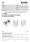
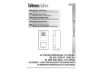
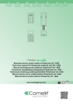
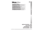
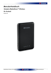
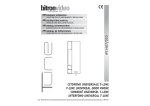
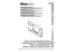
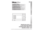
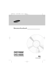
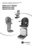
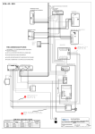
MANUALE ISTRUZIONI
CARATTERISTICHE DI FUNZIONAMENTO E INSTALLAZIONE
INSTRUCTIONS MANUAL
OPERATING AND INSTALLATION FEATURES
MANUEL D’INSTRUCTIONS
CARATERISTIQUES DE FONCTIONNEMENT ET INSTALLATION
BETRIEBSDATEN UND INSTALLATION
MANUAL DE ISTRUCCIONES
CARACTERÍSTICAS DE FUNCIONAMIENTO E INSTALACIÓN
AN9839/1
GEBRAUCHSANWEISUNG
CENTRALINO EUROBUS
EUROBUS CONCIERGE SWITCHBOARD
CENTRALE DE CONCIERGERIE EUROBUS
PFÖRTNER-ZENTRALE EUROBUS
CENTRALITA EUROBUS
DS909839-001
LBT90264
CENTRALINO DI PORTINERIA AN9839/1
ITALIANO
ll centralino permette le seguenti prestazioni:
• conversazione fonica con posti esterni
• apertura porta
• chiamata elettronica agli utenti
• possibilità di regolare il livello di chiamata fra alto, medio e basso
• possibilità di selezionare la modalità di funzionamento tra GIORNO/NOTTE
• possibilità di selezionare la modalità di gestione tra PARZIALE/TOTALE
• due segnalazioni a led a disposizione per segnalazioni ausiliarie (es. porta aperta)
CONTENUTO DELLA CONFEZIONE
La confezione contiene:
• Centralino Eurobus munito di borchia
• Base tavolo
• Manuale istruzioni
CARATTERISTICHE TECNICHE
Tensione di alimentazione nominale: ........................................................................................... 14Vac
Corrente massima assorbita: ............................................................................................................ 2A
Temperatura di funzionamento:.......................................................................................... 0°C ÷ +40°C
Temperatura di immagazzinamento: ................................................................................ - 10°C ÷ +60°C
Pulsante apriporta
INSTALLAZIONE
Led di STATO bicolore
Eseguire i collegamenti elettrici nell’apposita borchia di collegamento in funzione dell’impianto realizzato
(vedi schemi impianti allegati).
I morsetti presenti nella borchia sono i seguenti:
Pulsante Giorno/Notte
NOME
~
0
3
B+
BR
3
B+
LR+
LRLG+
LG-
FUNZIONE
Ingresso alimentazione 14Vac
Ingresso alimentazione 14Vac
Ingresso alimentazione colonna
Ingresso Eurobus +
Massa Eurobus
Ingresso / uscita segnale di reset
Uscita alimentazione positiva colonna
Uscita Eurobus +
Anodo Led rosso
Catodo Led rosso
Anodo Led verde
Catodo Led verde
Led verde disponibile dall’esterno
Pulsante abilitazione
fonia con P.E.
Pulsante TOTALE/PARZIALE
Pulsante chiamata posto interno
Pulsanti inoltro chiamata
Commutatore regolazione
volume chiamata
Fig. 2
USO
Il centralino prevede due differenti stati di funzionamento selezionabili dall’operatore:
I led disponibili sono utilizzabili fornendo una tensione continua di 12÷18Vdc ai loro capi.
RUBRICA
Per accedere e scrivere sulla rubrica collocata accanto al centralino, svitare le quattro viti di fissaggio, estrarre
la rubrica, compilarla debitamente e rimontarla con le quattro viti.
MODALITÁ NOTTE
Il LED di stato (Fig. 2) è spento.
In questa modalità il centralino è disattivato e l’impianto funziona come se lo stesso non esistesse, consentendo
ai visitatori di chiamare direttamente gli utenti, che possono ovviamente rispondere e aprire la serratura.
In questa modalità di funzionamento gli utenti non possono né chiamare né essere chiamati dal centralino.
In caso di mancanza di alimentazione, il centralino si comporterà come se si trovasse in modalità di
funzionamento “notte”. Al ritorno dell’alimentazione il centralino continuerà a funzionare in modalità
“notte”, indipendentemente dallo stato in cui era prima dello spegnimento.
Premendo il tasto
si abilita il centralino a funzionare in modalità “GIORNO”.
MODALITÁ GIORNO
In questa modalità il centralino è attivo e può funzionare in due differenti varianti, denominate: “TOTALE” e
“PARZIALE”.
Il pulsante “P/T” permette la selezione della modalità di funzionamento fra Totale e parziale.
All’accensione automaticamente viene settato in modalità TOTALE; premendo il pulsante si commuterà il
funzionamento del centralino, portandolo in modalità PARZIALE.
Lo stato del funzionamento è indicato dall’accensione in modalità continua o lampeggiante del led di stato
“S”.
Fig. 1
2
Led rosso disponibile dall’esterno
DS909839-001
DS909839-001
3
Modalità “Totale”
Il led “S” di stato è acceso di colore verde.
In questa modalità, il centralino intercetta tutte le chiamate in arrivo dal posto esterno e suona con nota
bitonale; nel momento in cui giunge una chiamata, il led “S” inizia a lampeggiare in rosso e rimarrà acceso in
rosso fino al termine della comunicazione.
Per rispondere alla chiamata, l’operatore deve sollevare il microtelefono e parlare TENENDO PREMUTO il tasto
. Per attivare l’elettroserratura occorre premere il pulsante “APRIPORTA”.
Dopo aver risposto, qualora si volesse chiamare un utente, è necessario digitare il codice relativo dell’utente
desiderato e premere il tasto
. Il led di stato da rosso lampeggiante, rimane acceso in rosso fisso per un
paio di secondi e poi commuta in giallo per indicare all’operatore che la chiamata è stata inoltrata e che si è in
attesa di risposta; per mettere in comunicazione l’utente chiamato con il posto esterno, è sufficiente premere
uno qualsiasi dei due tasti “R”. Si può mettere in comunicazione un utente chiamato dal centralino solo se il
centralino ha precedentemente ricevuto una chiamata dal posto esterno.
In ogni momento, ad eccezione di quando è già in corso una conversazione, qualsiasi utente può chiamare il
centralinista premendo il tasto di “APRIPORTA” presente sul suo citofono o videocitofono.
Anche il centralinista può chiamare qualsiasi utente in qualsiasi momento, semplicemente digitandone il
codice relativo seguito dalla pressione del tasto
.
Nel caso il centralinista dopo aver già chiamato un utente, mentre rimane in attesa di risposta (led di
stato è acceso in giallo), volesse chiamare un altro utente, deve necessariamente interrompere la chiamata
riappendendo il microtelefono per portare il centralino nella condizione di riposo. Quando il led di stato
tornerà ad accendersi in verde, il centralinista potrà eseguire una nuova chiamata.
ENGLISH
PACKING CONTENTS
The packing contains:
• Eurobus concierge switchboard provided with wiring junction box
• Table-top mounting base
• Instructions manual
TECHNICAL CHARACTERISTICS
Nominal power supply voltage: ................................................................................................... 14Vac
Maximum power consumption: .........................................................................................................2A
Working temperature: ....................................................................................................... 0°C ÷ +40°C
Storage temperature:..................................................................................................... -10°C ÷ +60°C
INSTALLATION
Perform electric connections in the suitable wiring junction box, according to the system design (see enclosed
system diagrams)
Terminal pins in wiring junction box are the following:
spento
Centralino in modalità di funzionamento NOTTE, praticamente disattivato.
verde
Centralino a riposo in modalità di funzionamento GIORNO TOTALE.
verde lampeggiante
Centralino a riposo in modalità di funzionamento GIORNO PARZIALE.
NAME
~
0
3
B+
BR
3
B+
LR+
LRLG+
LG-
rosso lampeggiante
Segnalazione che è arrivata una chiamata dal posto esterno.
The available leds can be used providing a 12÷18Vdc continuous voltage to their terminals.
rosso
Una comunicazione in corso sta per essere inoltrata.
giallo
La comunicazione è stata inoltrata all’utente desiderato e il centralino è in attesa
di risposta.
Modalità “Parziale”
Il led “S” è lampeggiante in colore verde.
In questa modalità, il centralino lascia che le chiamate transitino e arrivino direttamente al destinatario
indirizzato, ma può comunque chiamare e essere chiamato da tutti gli utenti.
LED S
Il led di stato “S” presente sulla cappa del centralino è un led bicolore e fornisce le seguenti indicazioni:
FUNCTION
14Vac power supply input
14Vac power supply input
Column power supply input
Eurobus input
Eurobus ground
reset signal input / output
Column power supply positive output
Eurobus output
Red led anode
Red led cathode
Green led anode
Green led cathode
DIRECTORY
To access and write on the directory located near the switchboard, unscrew the four fixing screws, extract the
directory, write it out properly and mount again it with the four screws.
COMANDO REGOLAZIONE VOLUME CHIAMATA
Sul centralino è possibile regolare il livello di chiamata del posto esterno fra alto, medio e basso per mezzo
di uno selettore accessibile dal bordo inferiore del centralino. Non è regolabile la chiamata in arrivo dai posti
interni.
Fig. 1
4
DS909839-001
DS909839-001
5
AN9839/1 CONCIERGE SWITCHBOARD
In this mode, the switchboard intercepts all the calls coming from the door unit and rings with a dual-tone
sound; when a call arrives, the led “S” starts blinking red and stays on until the conversation end.
To answer the call, the attendant must pick the handset up and speak BY KEEPING the button PRESSED. To
activate the electric lock, press the button “DOOR OPENER”.
After answering, to call a user it is necessary to enter the code associated to the desired user and press the
button
. The status led blinking red changes and becomes steady red for about two seconds and then
becomes yellow to indicate to the attendant that the call has been forwarded and the switchboard is waiting
for an answer; to connect the called user to the door unit, press one of the two “R” buttons. It is possible
to connect a user called by the switchboard only if the switchboard has received before a call from the door
unit.
At any time, except when a conversation is already in progress, any user can call the switchboard attendant by
pressing the “DOOR OPENER” button present on his door phone or video door phone.
Also the attendant can call any user at any time, simply by entering the associated code and then pressing
the button
.
If the attendant, after calling a user, while he is waiting for an answer (the status led is yellow), wants to
call another user, he must interrupt the first call by hanging the handset up, in order to put the switchboard
back in standby mode. When the status led will light again in green, the attendant will be able to perform a
new call.
The switchboard allows the following functions:
• Audio conversation with door units
• Door opening
• Electronic call to users
• Capability to adjust the ring level among high, medium and low
• Capability to select operating mode between DAY/NIGHT
• Capability to select the management mode between PARTIAL/TOTAL
• Two signalling leds available for auxiliary information (for ex. Open door)
Door opener button
Bicoloured STATUS led
Day/Night button
Green led available from outside
Button for audio
enabling with door unit
Red led available from outside
TOTAL/PARTIAL button
Apartment station call button
Call forwarding buttons
Switch for call volume adjusting
Fig. 2
USE
The switchboard has two different operating states, that can be selected by the attendant:
NIGHT MODE
The status LED (Fig. 2) is off.
In this mode, the switchboard is disabled and the system operates as if the switchboard was not present,
allowing visitors to directly call users, that of course can answer and open the door lock.
In this operating mode, users can not call or be called by the switchboard.
In case of mains fail, the switchboard will operate as if it was in “night” mode. After mains return, the
switchboard will continue to operate in “night” mode, regardless of the state it was before the poweroff.
By pressing the button
“Partial” mode.
The led “S” blinks in green.
In this mode, the switchboard allows all calls to pass and directly arrive to the called user, but, however, it
can call and be called by all the users.
S LED
The status led “S”, present on the switchboard cover, is a bicoloured led and provides the following
information:
off
Switchboard in NIGHT mode, deactivated.
green
Switchboard in standby, in TOTAL DAY mode.
green blinking
Switchboard in standby, in PARTIAL DAY mode.
red blinking
It signals the presence of a call coming from the door unit.
red
A communication in progress is going to be forwarded.
yellow
The communication has been forwarded to the desired user and the switchboard is
waiting for an answer.
COMMAND FOR RING VOLUME ADJUSTMENT
On the switchboard it is possible to adjust the ring level of calls coming from a door unit. The level can be
high, medium and low and can be adjusted with a switch accessible from the lower switchboard edge. It is not
possible to adjust the volume of calls coming from apartment stations.
, the switchboard is enabled to operate in “DAY” mode.
DAY MODE
In this mode the switchboard is active and can operate in two different ways, called “TOTAL” and “PARTIAL”.
The button “P/T” allows to select the operating mode between Total and Partial.
At power-on, it is automatically set in TOTAL mode; by pressing the button, the switchboard operating mode
will change in PARTIAL mode.
The operating mode is signalled by the status led “S”, that lights steady or blinking.
“Total” mode.
The status led “S” lights green.
6
DS909839-001
DS909839-001
7
ENTRALE DE CONCIERGERIE AN9839/1
FRANÇAIS
La centrale permet les fonctions suivantes:
• conversation audio avec les postes externes
• ouverture de la porte
• appel électronique aux utilisateurs
• possibilité de régler le niveau d’appel parmi haut, moyen et bas
• possibilité de sélectionner la modalité de fonctionnement entre JOUR/NUIT
• possibilité de sélectionner la modalité de gestion entre PARTIELLE/TOTALE
• deux led de signalisation disponibles pour signalisations auxiliaires (par ex. porte ouverte).
CONTENU DE LA CONFECTION
La confection contient:
• Centrale de conciergerie Eurobus dotée de boîte de connexion
• Base pour montage sur table
• Manuel d’instructions
CARACTERISTIQUES TECHNIQUES
Tension d’alimentation nominale: ........................................................................................... ... 14Vac
Courant max. absorbé: ............................................................................................................ ....... 2A
Température de fonctionnement:.........................................................................................0°C ÷ +40°C
Température de stockage: ...............................................................................................-10°C ÷ +60°C
Touche ouvre-porte
INSTALLATION
Led d’ETAT bicolore
Effectuer les branchements électriques dans la boîte de connexion disposée à cet effet, en fonction du système
réalisé (voir les diagrammes des systèmes ci-joints).
Les bornes présentes dans la boîte de connexion sont les suivantes:
NOM
FONCTION
~
0
3
B+
BR
3
B+
LR+
LRLG+
LG-
Entrée alimentation 14Vac
Entrée alimentation 14Vac
Entrée alimentation colonne
Entrée Eurobus +
Masse Eurobus
Entrée / sortie signal de mise à zéro
Sortie alimentation positive colonne
Sortie Eurobus +
Anode Led rouge
Cathode Led rouge
Anode Led verte
Cathode Led verte
Touche Jour/Nuit
Led verte disponible de l’extérieur
Touche d’habilitation phonie
avec poste externe
Led rouge disponible de l’extérieur
Touche TOTAL/PARTIAL
Touche appel poste interne
Touche de transfert d’appel
Interrupteur pour réglage du volume de l’appel
Fig. 2
UTILISATION
Les led disponibles peuvent être utilisées en fournissant une tension continue de 12÷18Vdc à leurs bornes.
REPERTOIRE
Pour accéder et écrire dans le répertoire situé à côté de la centrale, dévisser les quatre vis de fixation, extraire
le répertoire, le remplir de façon appropriée et le remonter avec les quatre vis.
La centrale prévoit deux modalités de fonctionnement qui peuvent être sélectionnées par l’opérateur:
MODALITE NUIT
La LED d’état (Fig. 2) est éteinte.
Dans cette modalité, la centrale est désactivée et le système fonctionne comme si elle n’existait pas, permettant
aux visiteurs d’appeler directement les utilisateurs, qui naturellement peuvent répondre et ouvrir la serrure.
Dans cette modalité de fonctionnement, les utilisateurs ne peuvent ni appeler ni être appelés par la centrale.
En cas de manque d’alimentation, la centrale de conciergerie fonctionne comme si elle se trouvait en
modalité de fonctionnement « nuit ». Quand l’alimentation revient, la centrale continue à fonctionner
en modalité « nuit », sans tenir compte de l’état où elle se trouvait avant d’être éteinte.
En appuyant sur la touche
, la centrale est habilitée à fonctionner en modalité « JOUR ».
MODALITE JOUR
Dans cette modalité, la centrale est active et peut fonctionner de deux façons différentes, appelées: « TOTALE »
et «PARTIELLE».
La touche “P/T” permet de sélectionner la modalité de fonctionnement entre Totale et Partielle.
A l’allumage, de façon automatique la modalité est TOTALE; en appuyant sur la touche on peut changer la
modalité de fonctionnement de la centrale, pour la faire devenir PARTIELLE.
L’état de fonctionnement est indiqué par l’allumage de la led d’état « S », en modalité continue ou
clignotante.
Fig. 1
8
DS909839-001
DS909839-001
9
Modalité “Totale”
La led d’état “S” est allumée en vert.
Dans cette modalité, la centrale intercepte tous les appels qui proviennent du poste externe et sonne avec un
son à double tonalité; quand un appel arrive, la led « S » commence à clignoter en rouge et reste allumée en
rouge jusqu’à la fin de la communication.
Pour répondre à l’appel, l’opérateur doit décrocher le combiné et parler en MAINTENANT la touche APPUYEE.
Pour activer l’électro-serrure il faut appuyer sur la touche « OUVRE-PORTE ».
Après avoir répondu, si on veut appeler un utilisateur il faut entrer le code associé à l’utilisateur désiré et
appuyer sur la touche
. La led d’état qui était rouge clignotante reste allumée en rouge fixe pendant deux
secondes à-peu-près et puis elle devient jaune pour signaler à l’opérateur que l’appel a été transféré et qu’on
est en train d’attendre une réponse; pour mettre en communication l’utilisateur appelé avec le poste externe,
il suffit d’appuyer sur l’un ou l’autre des deux touches « R ».
On peut mettre en communication un utilisateur appelé par la centrale de conciergerie seulement si, avant, la
centrale a reçu un appel provenant du poste externe.
A chaque moment, sauf quand il y a déjà une communication en cours, n’importe quel utilisateur peut appeler
l’opérateur en appuyant sur la touche « OUVRE-PORTE » située sur son interphone ou vidéophone.
Aussi l’opérateur peut appeler n’importe quel utilisateur à chaque moment, en entrant tout simplement le code
qui lui est associé et après en appuyant sur la touche
.
Si l’opérateur, après avoir appelé un utilisateur, pendant qu’il attend une réponse (la led d’état est allumée en
jaune), veut appeler un autre utilisateur, il doit nécessairement interrompre l’appel en raccrochant le combiné,
pour que la centrale soit en condition de veille. Quand la led d’état s’allumera de nouveau en vert, l’opérateur
pourra faire un nouvel appel.
Modalité “Partielle”
La led “S” clignote en vert.
Dans cette modalité, la centrale de conciergerie permet aux appels de passer et d’arriver directement à
l’utilisateur appelé, mais de toute façon elle peut appeler et être appelée par tous les utilisateurs.
LED S
La led d’état “S” située sur le couvercle de la centrale de conciergerie est une led bicolore; elle fournit les
informations suivantes:
éteinte
Centrale de conciergerie en modalité de fonctionnement NUIT, pratiquement
désactivée.
verte
Centrale de conciergerie en veille, en modalité de fonctionnement JOUR TOTALE.
verte clignotante
Centrale de conciergerie en veille, en modalité de fonctionnement JOUR
PARTIELLE.
rouge clignotante
Elle signale qu’il est arrivé un appel du poste externe.
rouge
Une communication en cours va être transférée.
jaune
La communication a été transférée à l’utilisateur désiré et la centrale de conciergerie
attend une réponse.
DEUTSCH
VERPACKUNGSINHALT
Die Verpackung enthält:
• Pförtnerzentrale Eurobus ausgestattet mit Kabelabschlussdose
• Tischstütze
• Bedienungsanleitungen
TECHNISCHE EIGENSCHAFTEN
Spannung der Nominalstromversorgung: ................................................................................ ..... 14V ac
max. Stromaufnahme: ............................................................................................................ ........ 2A
Betriebstemperatur: .........................................................................................................0°C ÷ +40°C
Lagertemperatur: ...........................................................................................................-10°C ÷ +60°C
INSTALLATION
Die elektrischen Anschlüsse in der dafür vorgesehenen Kabelabschlussdose abhängig vom Typ der Anlage
durchführen (siehe beigefügte Pläne).
Die Klemmen in der Kabelabschlussdose sind folgende:
NAME
~
0
3
B+
BR
3
B+
LR+
LRLG+
LG-
FUNKTION
Eingang Stromversorgung 14V ac
Eingang Stromversorgung 14V ac
Eingang Stromversorgung der Steigleitung
Eingang Eurobus +
Masse Eurobus
Eingang / Ausgang Reset-Signal
Ausgang Plus Stromversorgung der Steigleitung
Ausgang Eurobus +
Anode rote LED
Kathode rote LED
Anode grüne LED
Kathode grüne Led
Die verfügbaren LEDs sind verwendbar durch Versorgung an ihre Ende einer Gleichspannung von 12÷18V dc.
VERZEICHNIS
Um zum Verzeichnis neben der Zentrale zu gelangen und an es zu schreiben, die vier Schrauben lösen, das
Verzeichnis herausziehen, es ausführlich ausfüllen und mit den vier Schrauben wieder montieren.
COMMANDE DE REGLAGE DU VOLUME D’APPEL
Dans la centrale de conciergerie il est possible de régler la niveau de la tonalité des appels provenant du poste
externe. On peut choisir un niveau haut, moyen ou bas, par le biais d’un sélecteur accessible du bord inférieur
de la centrale. On ne peut pas régler le volume des appels provenant des postes internes.
Fig. 1
10
DS909839-001
DS909839-001
11
PFÖRTER-ZENTRALE AN9839/1
Betriebsmodus “Voll”
Die Status-LED “S” leuchtet Grün.
In diesem Modus fängt die Zentrale alle von Außenstelle ankommende Anrufe ab und klingelt mit einem
bitonalen Ton. Bei Erhaltung eines Anrufs beginnt die LED “S” rot zu blinken und sie bleibt rot eingeschaltet
bis zum Ende des Gesprächs.
Um den Anruf zu beantworten, muss der Bediener den Hörer abheben und UNTER GEDRÜCKTHALTEN der Taste
sprechen. Um die Elektroverriegelung zu aktivieren, muss die Taste “TURÖFFNER” gedrückt werden.
Will man nach der Antwort einen Teilnehmer anrufen, den Code des verlangenen Teilnehmers eingeben und die
Taste
drücken. Die rot blinkende Status-Led leuchtet dann stetig rot für einige Sekunden und dann ändert
sich in gelb, um dem Bediener die Anrufsweiterleitung und die Erwartung einer Antwort anzuzeigen. Um den
angerufenen Teilnehmer mit die Außenstelle in Verbindung zu stellen, eine der drei Tasten “R” drücken. Einen
von der Zentrale angerufenen Teilnehmer kann in Verbindung gestellt werden, nur wenn die Zentrale einen
Anruf von der Außenstelle erhaltet hat.
Jederzeit, ausgenommen während eines Gesprächs, kann jeder Teilnehmer beim Drücken der Taste “TÜRÖFFNER”
auf der Sprechanlage oder Videosprechanlage den Bediener anrufen.
Der Bediener selbst kann jederzeit irgendeinen Teilnehmer anrufen. Er muss einfach den Code eingeben und
dann die Taste
drücken.
Hat ein Bediener schon einen Teilnehmer angerufen und wartet er gerade auf eine Antwort, kann er während
dieser Zeit keinen anderen Teilnehmer anrufen (Status-LED leuchtet gelb). Er muss unbedingt den Anruf beim
Einhängen des Hörers aufhören, um die Zentrale in Ruhemodus wiederzusetzen. Nur wenn die Status-Led wieder
grün leuchtet, kann der Bediener einen neuen Anruf machen.
Die Zentrale ermöglicht die folgenden Leistungen:
• Gespräch mit Außenstellen
• Turöffnung
• Elektronischen Anruf an Teilnehmer
• Möglichkeit der Einstellung der Ruftonlautstärke unter laut, mittel und leise
• Möglichkeit der Auswahl des Betriebsmodus zwischen TAG/NACHT
• Möglichkeit der Auswahl des Verwaltungsmodus zwischen PARTIELL/VOLL
• Verfügung über zwei Anzeige-LEDs für Hilfsanzeigen (z.B. Tür offen)
Türöffnertaste
Zweifarbige Status-LED
TAG/NACHT Taste
Grüne LED von außen verfügbar
Aktivierungstaste des Gesprächs
mit Außenstelle
Rote LED von außen verfügbar
Betriebsmodus “Partiell”
Die LED “S” blinkt grün.
In diesem Modus lässt die Zentrale die Anrufe durch und diese direkt zum adressierten Empfänger ankommen.
Die Zentrale kann auf jeden Fall anrufen und von allen Teilnehmern angerufen werden.
PARTIELL/VOLL Taste
Anruftaste Innenstelle
Tasten Anrufsweiterleitung
Umschalter Einstellung der Ruftonlautstärke
LED S
Die Status-LED “S” auf dem Deckel der Zentrale ist eine zweifarbige LED und gibt die folgenden Anzeigen:
Ausgeschaltet
Zentrale im Betriebsmodus NACHT, d.h. deaktiviert.
Grün
Zentrale in Ruhestellung im Betriebsmodus TAG VOLL.
GEBRAUCHSANLEITUNG
Grün blinkend
Zentrale in Ruhestellung im Betriebsmodus TAG PARTIELL.
Die Zentrale sieht zwei verschiedene Betriebsmodi vor, die vom Bediener ausgewählt werden können:
Rot blinkend
Zeigt an, dass ein Anruf von der Außenstelle angekommen ist.
Rot
Eine laufende Kommunikation wird gleich weitergeleitet.
Gelb
Die Kommunikation wurde dem erwünschten Teilnehmer weitergeleitet und die
Zentrale wartet auf eine Antwort.
Fig. 2
MODUS NACHT
Die Status-LED (Fig. 2) ist ausgeschaltet.
In diesem Modus ist die Zentrale deaktiviert und die Anlage funktioniert, als ob die nicht existierte. Die
Besucher können die Teilnehmer direkt anrufen, welche selbstverständlich antworten und die Verriegelung
öffnen können.
In diesem Betriebsmodus können die Teilnehmer weder anrufen noch von der Zentrale angerufen werden.
Im Fall eines Versorgungsausfall verhält die Zentrale sich, als ob sie im Betriebsmodus “Nacht” wäre.
Sobald die Stromzufuhr wieder gegeben ist, funktioniert die Zentrale im Modus “Nacht” und das
unabhängig vom Status, in dem sie sich vor der Ausschaltung befand.
Beim Drücken der Taste
STEUERUNG DER EINSTELLUNG DER RUFTONLAUTSTÄRKE
Auf der Zentrale kann die Ruftonlautstärke der Außenstelle unter laut, mittel und leise geregelt werden. Die
Einstellung erfolgt über einen Schalter, welcher vom Unterteil der Zentrale erreichbar ist. Der von Innenstelle
ankommende Anruf ist nicht einstellbar.
wird die Zentrale aktiviert, um in Modus “TAG” zu funktionieren.
MODUS TAG
In diesem Modus ist die Zentrale aktiv und kann in zwei verschiedenen Varianten funktionieren, die “VOLL”
und“PARTIELL” genannt werden.
Die Taste “P/V” ermöglicht zwischen den vollständigen und den partiellen Betriebsmodus zu wählen.
Bei der Einschaltung wird die Zentrale automatisch in Vollbetriebsmodus eingestellt. Beim Drücken der Taste
wird den Betriebsmodus der Zentrale verändert und sie in den partiellen Betriebsmodus gebracht..
Der Betriebstatus wird durch stetiges oder blinkendes Einschalten der Status-LED “S” angezeigt.
12
DS909839-001
DS909839-001
13
CENTRALITA DE RECEPCIÓN AN9839/1
ESPAÑOL
La centralita permite las siguientes prestaciones:
• conversación fónica con microaltavoces
• apertura de la puerta
• llamada electronica hacia los usuarios
• posibilidad de regular el nivel de llamada entre alto, medio y bajo
• posibilidad de seleccionar la modalidad de funcionamiento entre DÍA/NOCHE
• posibilidad de seleccionar la modalidad de gestión entre PARCIAL/TOTAL
• dos señalaciones con led a disposición para señalaciones auxiliares (ej. Puerta abierta)
CONTENIDO DE LA CONFECCIÓN
La confección contiene:
• Centralita Eurobus proveido de tachuela
• Base mesa
• Manual instrucciones
CARACTERISTICAS TECNICAS
Tensión de alimentación nominal: ............................................................................................... 14Vac
Corriente máxima absorbida: ........................................................................................................... 2A
Temperatura de funcionamiento: .........................................................................................0°C ÷ +40°C
Temperatura de almacenamiento: .....................................................................................-10°C ÷ +60°C
Tecla apertura de la puerta
INSTALACIÓN
Led de ESTADO bicolor
Efectuar las conexiones electricas en la respectiva tachuela de conexión a según del sistema realizado (consultar
esquemas de los sistemas)
Los bornes situados en la tachuela son los siguientes:
NOMBRE
~
0
3
B+
BR
3
B+
LR+
LRLG+
LG-
FUNCIÓN
Entrada alimentación 14Vac
Entrada alimentación 14Vac
Entrada alimentación columna
Entrada Eurobus +
Masa Eurobus
Entrada / salida señal de reset
Salida alimentación positiva columna
Salida Eurobus +
Ánodo Led rojo
Cátodo Led rojo
Ánodo Led verde
Cátodo Led verde
Tecla Día/Noche
Led verde disponible por el externo
Tecla abilitación fónia
con microaltavoz
Led rojo disponible por el externo
Tecla TOTAL/PARCIAL
Tecla llamada interfóno
Tecla tramitación llamada
Conmutador regulación volumen llamada
Fig. 2
USO
Los led disponibles son utilizables generando una tensión continua de 12÷18Vdc entre ellos.
La centralita prevee dos diferentes estados de funcionamiento seleccionables por el operador:
REGISTRO
MODALIDAD NOCHE
El LED de estado (Fig. 2) esta apagado.
En esta modalidad la centralita esta desactivada y el sistema funciona como si el mismo no existiera, permitiendo
a los visitantes de llamar directamente a los usuarios, que pueden responder y abrir la cerradura.
En esta modalidad de funcionamiento los usuarios no pueden ni llamar ni ser llamados por la centralita.
En caso de falta de alimentación, la centralita se comportará como se comporta en modalidad de
funcionamiento “noche”. Al regresso de la alimentación la centralita continua a funcionar en modalidad
“noche”, sin considerar el estado precedente a la falta de alimentación.
Para acceder y escribir en el registro situado junto a la centralita, destornillar los cuatro tornillos de fisaje,
quitar el registro, compilar y remontar el registro con los cuatro tornillos.
Presionando la tecla
MODALIDAD DÍA
En esta modalidad la centralita esta activa y puede funcionar en dos modos diferentes, llamados: “TOTAL” y
“PARCIAL”.
La tecla “P/T” permite la selección de la modalidad de funcionamiento entre Total y parcial.
Con la activación automatica viene seleccionada la modalidad TOTAL; presionando la tecla se conmuta la
modalidad de la centralita, poniendolo en modalidad PARCIAL.
El estado del funcionamiento viene indicado por la activación en modalidad continua o intermitente del led
de estado “S”.
Fig. 1
14
se activa la centralita a funcionar en modalidad “DÍA”.
DS909839-001
DS909839-001
15
Centralita en descanso en modalidad de funcionamiento DÍA TOTAL.
verde intermitente
Centralita en descanso en modalidad de funcionamiento DÍA PARCIAL.
rojo intermitente
Señalación que ha llegado una llamada por el microaltavoz.
rojo
Una comunicación activa esta por ser tramitada.
amarillo
La comunicación ha sido tramitada al usuario deseado y la centralita esta en espera
de respuesta.
AV1407/102
AV1407/102
OFF-SET =0
AN6215/L
P
1
2
Au
Au
AV 1407/004
AN 9839/1
B+
LGLG+
in
LRLR+
3
0
P5
P6
P7
P8
Ap
_0
RETE
MAINS
SECTEUR
NETZ
RED
RETE
MAINS
SECTEUR
NETZ
RED
0
230
AV 1142
0
230
B+
3
Borchia Centralino
Switchboard wire
junction box
Boîte de connexion
de la centrale de
conciergerie
Kabelabschlussdose
Tachuela Centralita
C
C
0
12
AN 1299
out
_
+
_
_
_
+
_
_
AN 9524/L
DS909839-001
1
2
4
8
16
32
64
128
AV1407/102
AV 1407/002
0
R
I
B_
B+
CD
CP
CD
CH
CP
P
DS909839-001
1
2
AN9854/8
CD 5-8
CD 1-4
Serratura
Lock
Serrure
Schloss
Cerradura
1
2
4
8
16
32
64
128
1
F
on
1
F
off
on
1
2
128
64
32
16
8
4
2
1
AV 1407/004
off
P
1
2
Au
Au
P
1
2
Au
Au
AV 1407/002
R
B-
CONTROL REGULACIÓN VOLUMEN LLAMADA
En la centralita es posible regular el nivel de llamada del microaltavoz entre alto, medio y bajo por medio
de un selector accesible por el borde inferior de la centralita. No es regulable la llamada en entrada por los
interfónos.
1
2
on
1
F
AV1407/102
P1
P2
P3
P4
L
L
16
1
F
off
128
64
32
16
8
4
2
1
on
1
2
off
P
1
2
Au
Au
C
P1
P2
P3
P4
P5
P6
P7
P8
verde
cavetto con connettore
cable with connector
câble avec connecteur
Kabel mit Verbinder
cable con conector
AN9847/L
Centralita en modalidad de funcionamiento NOCHE, osea desactivado.
Note:
- Max. estensione dell’impianto = 200 m.
- Per la programmazione delle decodifiche AV1407/102 seguire le istruzioni
del manuale prodotto.
- Per il corretto funzionamento dell’impianto escludere il segreto di conversazione.
Notes:
- System max. extension = 200 m.
- For AV1407/102 decoders programming, follow the instructions
in the product manual.
- For the system correct operation, exclude the conversation privacy function.
Notes:
- Extension maximale du système = 200 m.
- Pour la programmation des décodages AV1407/102, suivre les instructions
dans le manuel du produit.
- Pour le fonctionnement correct du système, exclure la fonction de secret
de la conversation.
Anmerkungen:
- Max. Anlagenerweiterung = 200 m.
- Für die Programmierung des Dekoders AV1407/102 die Gebrauchsanweisungen
des Produkts folgen.
- Für den korrekten Betrieb der Anlage die Mithörsperre ausschließen.
Avisos:
- Máx. extensión del sistema = 200 m.
- Para la programación de los descifres AV1407/102 seguir las instrucciones
del manual producto.
- Para el correcto funcionamiento del sistema excluir el secreto de conversación.
on/off
apagado
Colonna
Riser
Colonne
Steiger
Columna
on/off
LED S
El led de estado “S” situado en la cubierta de la centralita es un led bicolor y muestra las siguientes
indicaciones:
All rights reserved - Diritti riservati a Norma di Legge
on/off
Modalidad “Parcial”
El led “S” esta activo de color verde intermitente.
En esta modalidad, la centralina deja que las llamadas pasen y lleguen directamente al destinatario deseado,
pero puede de iguales maneras llamar y ser llamado por todos los usuarios.
BV-CEB-0021
IMPIANTO CITOFONICO SISTEMA “Eurobus”, CON 1 POSTO ESTERNO, 1 COLONNA CON CENTRALINO DI PORTINERIA
“Eurobus” DOOR PHONE SYSTEM, WITH 1 DOOR UNIT, 1 COLUMN WITH CONCIERGE SWITCHBOARD
SYSTEME D'INTERPHONE “Eurobus”, AVEC 1 POSTE EXTERNE, 1 COLONNE AVEC CENTRALE DE CONCIERGERIE
SPRECHANLAGE SYSTEM “Eurobus” MIT 1 AUßENSTELLE, 1 STEIGLEITUNG MIT PFÖRTER-ZENTRALE
SISTEMA INTERFÓNICO SISTEMA “Eurobus”, CON 1 MICROALTAVOZ, 1 COLUMNA CON CENTRALITA DE PORTERÍA
on/off
Modalidad “Total”
El led “S” de estado es activo de color verde.
En esta modalidad, la centralita intercepta todas las llamadas en entrada por el microaltavoz y suena con nota
bitonal; en el momento que llega una llamada, el led “S” se activa intermitente de color rojo y quedará activo
en rojo hasta el acabar de la comunicación.
Para responder a la llamada, el operador tiene que descolgar el interfóno y hablar TENIENDO PRESIONADA la
tecla . Para activar la cerradura electrica se necesita presionar la tecla “APERTURA DE LA PUERTA”.
Después de haber respuesto, si se desea llamar un usuario, es necesario digitar el codigo del usuario que se desea
llamar y presionar la tecla
. El led de estado de color rojo intermitente se mantiene activo en rojo fijo por
un par de segundos y después conmuta en amarillo para indicar al operador que la llamada ha sido trámitada
y que esta esperando la respuesta; para poner en comunicación el usuario llamado con el microaltavoz, es
suficiente presionar una qualquiera de las dos teclas “R”. Se puede poner en comunicación un usuario llamado
por la centralita solo si la centralita ha anteriormente recibido una llamada por el microaltavoz.
En cada momento, con excepción de cuando hay una conversación activa, qualquier usuario puede llamar al
telefónista presionando la tecla de “APERTURA PUERTA” situado en el interfóno o videointerfóno.
También el telefónista puede llamar a qualquier usuario en qualquier momento, digitando solo el godigo
relativo seguido por la presión de la tecla
.
En el caso que el telefónista después de haber llamado un usuario, mientras esta en espera de respuesta (led
de estado esta encendido de color amarillo), quisiera llamar otro usuario, deve absolutamente interrumpir la
llamada colgando el interfóno para poner la centralita en la condición de descanso. Cuando el led de estado se
activa de color verde, el telefónista podrá efectuar una nueva llamada.
AV 1142
RETE
MAINS
SECTEUR
NETZ
RED
ap. ext.
17
BV-CEB-0025
BV-VEB-0043
IMPIANTO CITOFONICO SISTEMA “Eurobus”, CON 1 POSTO ESTERNO, 1 COLONNA CON CENTRALINO DI PORTINERIA
“Eurobus” DOOR PHONE SYSTEM, WITH 1 DOOR UNIT, 1 COLUMN WITH CONCIERGE SWITCHBOARD
SYSTEME D'INTERPHONE “Eurobus”, AVEC 1 POSTE EXTERNE, 1 COLONNE AVEC CENTRALE DE CONCIERGERIE
SPRECHANLAGE SYSTEM “Eurobus” MIT 1 AUßENSTELLE, 1 STEIGLEITUNG MIT PFÖRTER-ZENTRALE
SISTEMA INTERFÓNICO SISTEMA “Eurobus”, CON 1 MICROALTAVOZ, 1 COLUMNA CON CENTRALITA DE PORTERÍA
IMPIANTO VIDEOCITOFONICO (SISTEMA “Eurobus”), CON 1 POSTO ESTERNO, 1 COLONNA (con centralino di portineria)
VIDEO DOOR PHONE SYSTEM (“Eurobus” SYSTEM), WITH 1 DOOR UNIT, 1 COLUMN (with concierge switchboard)
SYSTEME DE VIDEOPHONE (SYSTEME “Eurobus”), AVEC 1 POSTE EXTERNE, 1 COLONNE (avec centrale de conciergerie)
VIDEOSPRECHANLAGE (SYSTEM “Eurobus”) MIT 1 AUßENSTELLE, 1 STEIGLEITUNG ( mit Pförtner-Zentrale)
SISTEMA INTERFÓNICO (SISTEMA “Eurobus”), CON 1 MICROALTAVOZ, 1 COLUMNA (con centralita de portería)
All rights reserved - Diritti riservati a Norma di Legge
All rights reserved - Diritti riservati a Norma di Legge
AV1407/102
AV1407/102
1
2
4
8
16
32
64
128
1
F
1
2
AV1407/102
AV 1407/002
P
1
2
Au
Au
AV 1407/004
cavetto con connettore
cable with connector
câble avec connecteur
Kabel mit Verbinder
cable con conector
Est
Int
E R
AP2
AP1
AP
0
_
CH
CD
X
CP
Y
C1
C2
Ultima di ogni colonna
Last of every column
Dernière de chaque colonne
Letzte in jeder Steigleitung
Ultima de cada columna
AN 9839/1
OFF-SET =0
AV 0052/20
B+
I
RI
R
R0
AV 0086/02E
B+
LRLR+
out
1
2
3
4
8
16
32
64
S
P1
P2
P3
P4
P5
P6
RETE
MAINS
SECTEUR
NETZ
RED
0
0
230
_
+
_
_
AV 1142
AV 0045/06E
in
3
0
C
RETE
MAINS
SECTEUR
NETZ
RED
4
0
230
2
Borchia Centralino
Switchboard wire
junction box
Boîte de connexion
de la centrale de
conciergerie
Kabelabschlussdose
Tachuela Centralita
1
L
L
_
Q2
Q2
Q1
Q1
Jp1
PT1
PT2
SW1
AV 2850/52 +
AV 2850/1
L
H
M
LD PA
LD
P
T
C
E
B
A
3
1
M
LD PA
LD
P
T
C
E
B
A
3
1
PT1
PT2
AV 2850/52 +
AV 2850/1
SW1
H
AK 7513
4
3
2
L
Q1
Q1
Q2
Q2
LD
P
T
C
E
B
A
3
1
1
AB3 1 ABABABAB
off
J1
segreto
AV1423/012 +
AV1423/001 - AV1423/002
AN 9839/1
0
R
I
B_
B+
CD
CP
R
BB+
LGLG+
in
LRLR+
3
P5
P6
P7
P8
1
3
A
B
V
S
0
CP
CH
CD
9
AN 6074/L - AN6330/L
AV 1142
H
doppino twistato
twisted pair
couple tressés
geflochtene Schleife
par trenzado
CD 5-8
CD 1-4
+
C
Off
SW1
P1
P2
P3
P4
Ap
_
+
_
_
L
Q3
0
68-75
OHM
B+
3
3
AB3 1 ABABABAB
LGLG+
Jp1
1 2 3 4 5 6 7 8 On
On
Q3
AN6215/L
AK 7513
R
B-
Segreto
Off
On
AN9854/8
AN9847/L
RC TP
Off
Serratura
Lock
Serrure
Schloss
Cerradura
ap. ext.
on
1
F
off
off
on
1
2
128
64
32
16
8
4
2
1
AV 1407/004
Colonna / Riser
Colonne / Steiger
Columna
Segreto
Off
12345678
ON
Au
Au
On
C
P1
P2
P3
P4
P5
P6
P7
P8
1
2
4
8
16
32
64
128
P
1
2
on
1
2
Note:
- Con i monitor AV2850/1 aggiungere filo “T”
- In impianti con distributore video, controllare che nei
monitor il selettore impedenza sia posizionato su “L”
- Max. estensione complessiva dell’impianto = 200 m.
- Per il corretto funzionamento dell’impianto escludere il segreto di conversazione.
Notes:
- With AV2850/1 monitors, add “T” wire.
- In systems with video splitter, check that in monitors the impedance selector is
in “L” position
- System max. extension = 200 m.
- For the system correct operation, exclude the conversation privacy function.
Notes:
- Avec les moniteurs AV2850/1, ajouter le fil “T”
- Dans les systèmes avec distributeur vidéo, vérifier que dans les moniteurs
le sélecteur d'impédance soit positionné sur “L”
- Extension maximale totale du système = 200 m.
- Pour le fonctionnement correct du système, exclure la fonction de secret
de conversation.
Anmerkungen:
- Mit Monitoren AV2850/1 Kabel “T” hinzufügen
- In Anlagen mit Videoverteiler ist zu prüfen, dass der Schalter in den Monitoren auf
Position “L” steht
- Max. Anlagenerweiterung = 200 m.
- Für den korrekten Betrieb der Anlage die Mithörsperre ausschließen.
Avisos:
- Con los monitores AV2850/1 agregar el hilo “T”
- En sistemas con distribuidor vidéo, controlar que en los monitores el selector
impedancia sea posicionado en “L”
- Máx. extensión total del sistema = 200 m.
- Para el correcto funcionamiento del sistema excluir el secreto de conversación.
12345678
AV1407/102
1
F
off
128
64
32
16
8
4
2
1
on
off
1
F
on/off
ap. ext.
Colonna / Riser
Colonne / Steiger
Columna
on/off
2
Au
Au
Connettore Bus con collegamenti
BUS Connector with connection
Connecteur BUS avec connections
Busverbinder mit Anschlüssen
Conector Bus con conexiones
on/off
Serratura
Lock
Serrure
Schloss
Cerradura
Connettore di Chiusura senza collegamenti
Closure Connector without connection
Connecteur Fermeture sans connections
Abschlussverbinder ohne Anschlüsse
Conector de Cierre sin conexiones
on/off
Note:
- Max. estensione complessiva dell’impianto = 200 m.
- Per la programmazione delle decodifiche AV1407/102 seguire le istruzioni del manuale prodotto.
- Per il corretto funzionamento dell’impianto escludere il segreto di conversazione.
- Nel posto esterno AV0052/20-22 settare i ponticelli (RC-TP-E-R) secondo le istruzioni del manuale
Notes:
- System max. extension = 200 m.
- For AV1407/102 decoders programming, follow the instructions in the product manual.
- For the system correct operation, exclude the conversation privacy function.
- In AV0052/20-22 door unit, set the jumpers (RC-TP-E-R) following the manual instructions.
Notes:
- Extension maximale totale du système = 200 m.
- Pour la programmation des décodages AV1407/102, suivre les instructions
dans le manuel du produit.
- Pour le fonctionnement correct du système, exclure la fonction de secret de conversation.
- Dans le poste externe AV0052/20-22 placer les pontets (RC-TP-E-R) selon
les instructions du manuel
Anmerkungen:
- Max. Anlagenerweiterung = 200 m.
P
- Für die Programmierung des Dekoders AV1407/102 die
1
1
2
Gebrauchsanweisungen des Produkts folgen.
2
Au
- Für den korrekten Betrieb der Anlage die Mithörsperre ausschließen.
Au
- In der Außenstelle AV0052/20-22 die Steckbrücken (RC-TP-E-R) gemäß den
Gebrauchsanleitungen erstellen.
AV 1407/002
Avisos:
- Máx. extensión total del sistema = 200 m.
- Para la programación de los descifres AV1407/102 seguir las instrucciones
del manual producto.
- Para el correcto funcionamiento del sistema excluir el secreto de conversación
- En el microaltavoz AV0052/20-22 conectar los puentes de conexiones
P
(RC-TP-E-R) según las instrucciones del manual
1
out
RETE
MAINS
SECTEUR
NETZ
RED
0
230
_
+
_
_
B+
3
Borchia Centralino
Switchboard wire
junction box
Boîte de connexion
de la centrale de
conciergerie
Kabelabschlussdose
Tachuela Centralita
C
AV 1142
RETE / MAINS
SECTEUR / NETZ / RED
eventuale filo di autoeccitazione
possible self-lighting wire
eventuelle fil de autoallumage
eventueller Draht für die Selbstaktivierung
eventual cable de autoactivación
0
230
_
+
_
_
C
AV 1142
3M
1
3C
_
+
D
R
230
0
RETE
MAINS
SECTEUR
NETZ
RED
NA
N
NC
P
AV 7362
18
DS909839-001
DS909839-001
19
BV-VEB-0045
IMPIANTO VIDEOCITOFONICO (SISTEMA “Eurobus”), CON 1 POSTO ESTERNO, 1 COLONNA (con centralino di portineria)
VIDEO DOOR PHONE SYSTEM (“Eurobus” SYSTEM), WITH 1 DOOR UNIT, 1 COLUMN (with concierge switchboard)
SYSTEME DE VIDEOPHONE (SYSTEME “Eurobus”), AVEC 1 POSTE EXTERNE, 1 COLONNE (avec centrale de conciergerie)
VIDEOSPRECHANLAGE (SYSTEM “Eurobus”) MIT 1 AUßENSTELLE, 1 STEIGLEITUNG ( mit Pförtner-Zentrale)
SISTEMA INTERFÓNICO (SISTEMA “Eurobus”), CON 1 MICROALTAVOZ, 1 COLUMNA (con centralita de portería)
All rights reserved - Diritti riservati a Norma di Legge
Colonna / Riser
Colonne / Steiger
Columna
Segreto
Off
12345678
Off
Jp1
L
1 2 3 4 5 6 7 8 On
Off
On
Q3
Q3
Q2
Q2
Q1
Q1
Jp1
SW1
H
PT1
AV 2850/52 +
AV 2850/1
L
H
M
LD PA
LD
P
T
C
E
B
A
3
1
M
LD PA
LD
P
T
C
E
B
A
3
1
PT2
SW1
PT1
PT2
AV 2850/52 +
AV 2850/1
SW1
H
AK 7513
4
3
2
1
AB3 1 ABABABAB
off
J1
segreto
AV1423/012 +
AV 1423/001 - AV1423/002
Ultima di ogni colonna
Last of every column
Dernière de chaque colonne
Letzte in jeder Steigleitung
Ultima de cada columna
4
L
Q1
Q1
Q2
Q2
LD
P
T
C
E
B
A
3
1
AK 7513
3
2
1
AB3 1 ABABABAB
SC RC
AV 0060/00
AV 0078/00
Est
Int
AP CL
0
+
1/ _
CH
A
B
E
3
Y
CP
X
CD
C2
C1
AP
B+
I
RI
R
R0
AV 0086/02E
AN 9839/1
68-75
OHM
R
BB+
AV 0045/06E
LRLR+
0
doppino twistato
twisted pair
couple tressés
geflochtene Schleife
par trenzado
RETE / MAINS
SECTEUR
NETZ / RED
out
B+
3
Borchia Centralino
Switchboard wire
junction box
Boîte de connexion
de la centrale de
conciergerie
Kabelabschlussdose
Tachuela Centralita
0
230
_
+
_
_
1
2
3
4
8
16
32
64
S
0
LGLG+
in
3
C
AV 1142
3M
1
3C
P1
P2
P3
P4
P5
P6
20
Segreto
Off
On
ON
ap. ext.
Serratura
Lock
Serrure
Schloss
Cerradura
On
12345678
Note:
- Con i monitor AV2850/1 aggiungere filo “T”
- In impianti con distributore video, controllare che nei
monitor il selettore impedenza sia posizionato su “L”
- Max. estensione complessiva dell’impianto = 200 m.
- Per il corretto funzionamento dell’impianto escludere il segreto di
conversazione.
Notes:
- With AV2850/1 monitors, add “T” wire.
- In systems with video splitter, check that in monitors the impedance
selector is in “L” position
- System max. extension = 200 m.
- For the system correct operation, exclude the conversation privacy function.
Notes:
- Avec les moniteurs AV2850/1, ajouter le fil “T”
- Dans les systèmes avec distributeur vidéo, vérifier que dans les moniteurs
le sélecteur d'impédance soit positionné sur “L”
- Extension maximale totale du système = 200 m.
- Pour le fonctionnement correct du système, exclure la fonction de secret
de conversation.
Anmerkungen:
- Mit Monitoren AV2850/1 Kabel “T” hinzufügen
- In Anlagen mit Videoverteiler ist zu prüfen, dass der Schalter in den
Monitoren auf Position “L” steht
- Max. Anlagenerweiterung = 200 m.
- Für den korrekten Betrieb der Anlage die Mithörsperre ausschließen.
Avisos:
- Con los monitores AV2850/1 agregar el hilo “T”
- En sistemas con distribuidor vidéo, controlar que en los monitores el
selector impedancia sea posicionado en “L”
- Máx. extensión total del sistema = 200 m.
- Para el correcto funcionamiento del sistema excluir el secreto
de conversación.
AV 7362
+
_
D
R
eventuale filo di autoeccitazione
possible self-lighting wire
eventuelle fil de autoallumage
eventueller Draht für die Selbstaktivierung
eventual cable de autoactivación
230
0
RETE / MAINS
SECTEUR / NETZ / RED
NA
N
NC
P
DS909839-001
DS909839-001
21
22
DS909839-001
DS909839-001
23
Bitron Video adotta una politica di continuo sviluppo. Bitron Video
si riserva il diritto di effettuare modifiche e miglioramenti a qualsiasi
prodotto descritto nel presente documento senza preavviso.
Bitron Video follows a policy of continuous evolution of its products.
Therefore Bitron Video reserves the right to introduce changes or
modifications all its products in any moment and without prior
notice.
Bitron Video applique une mèthode de dèveloppement continu.
Par conséquent, Bitron Video se réserve le droit d’apporter des
changements et des améliorations à tout produt décrit dans ce
document, sans aucun préavis.
Bitron Video verfolgt eine Strategie der kontinuierlichen Entwicklung
und behält sich daher das Recht auf Änderungen und Verbesserungen
an jedem in dieser Anleitung beschriebenen Produkt ohne
Vorankündigung vor.
Bitron Video sigue una política de constante desarrollo; por lo tanto,
se reserva el derecho de aportar modificaciones y mejoras a cualquier
producto descrito en este documento sin aviso previo.
BITRON VIDEO S.r.l.
Via Albenga, 125
10090 Rivoli, Cascine Vica (Torino) Italy
Tel. +39 011 5531700 (r.a.) - Fax +39 011 5531720
http://www.bitronvideo.it
e-mail: [email protected]
DS909839-001
LBT90264