1
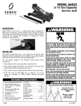
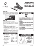
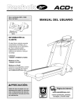
Operating Instructions • Warning Information • Parts Breakdown MODEL 4940A 4 Ton Ram Kit Operating Instructions RELEASE VALVE Turn knob clockwise and pump handle for applying pressure. Turn knob counterclockwise to release pressure. PUMP POSITION do not overload. overloading is indicated by bowing extension tubes or slipping attachments and can result in personal injury or damage to the equipment. It is possible to hold pump in any position from horizontal to vertical, but always keep the hose end of the pump down when above the horizontal position. when offset attachments are used, the rated capacity is always reduced by 50%. for each extension tube used in the setup, the overall rated capacity is reduced an additional 50%. refer to the operating instructions provided for typical setups and corresponding load capacities. IMPORTANT: Before attempting to raise a vehicle, check vehicle service manual for recommended lifting surfaces. PORTABLE RAM KIT PUMP BLEEDING PROCEDURES: The following bleeding procedure may be required before initial use: 1. Open oil fill screw three or four turns. 2. Attach the ram to the pump. 3. Close the release valve and pump the ram out as far as it will go. 4. Release the ram until the first drop of oil comes out of the oil fill hole. 5. Tighten up the oil fill screw and release the ram all of the way. 6. Make sure the pump is full of fluid after steps 1-5 are completed. This ends the bleeding procedure. The pump and ram should be working at full stroke. prior to applying a load, insure that all attachments and extension tubes are fully engaged. Insure load is centrally applied to attachments and ram saddle to minimize an off-center load condition. never use this equipment without a force gauge to verify the actual load being applied for various types of setups used. Read, study, and understand all warnings and operating instructions furnished with this portable ram Kit before use. failure to heed these warnings may result in loss of load, damage to jack and/or failure resulting in personal injury or property damage. do not overload beyond rated capacity. use only on hard, level surfaces capable of sustaining the load. do not open oil filler plug unless ram is fully retracted. always wear safety glasses when using this equipment. do not use as a vehicle lifting device or as a vehicle support. failure to heed these warnings may result in loss of load, damage to jack and/or failure resulting in personal injury or property damage. © 2006 Sunex Tools 4940A rev. 08/10/06 Operating Instructions • Warning Information • Parts Breakdown MODEL 4940A 4TON Item No. 1 2 3 4 5 6 7 8 9 10 11 12 13 14 15 16 17 18 Part NO. RS4940A01 Rs4940A02 RS4940A03 RS4940A04 RS4940A05 RS4940A06 RS4940A07 RS4910A07 RS4940A09 RS4940A10 RS4940A11 RS4940A12 RS4940A13 RS4940A14 RS4940A15 RS4940A16 RS4940A17 RS4940A18 Description 1 Storage Case 19.5" Extension Bar 16.5" Extension Bar 8.5" Extension Bar 5" Extension Bar 3" Extension Bar Serrated Cap Spreading Wedge Rubber Head Base Plate Ram Toe Plunger Cleft Cap V Base Male Connector 4 Ton Pump Unit W/Hose Ram Unit Hydraulic Hose 16 18 17 2 3 4 6 8 7 Hydraulic Spreader Assembly 9 10 11 12 13 14 15 Hydraulic BODY & FRAME PUMP S13 S12 S11 S10 *S7 RS4940A-S10A Coupling Assembly P29 P25 P28 *S8 *P19 * Included in RS4940A-RSK and RS4910A-RSK Seal Kits P26 P25A *P36 *P17 Hydraulic Ram Assembly *P12 *P11 *P10 RS4940ATP 4 Ton Thread Protector Ring *P03 P06 *R03 *P11 *P14 *R04 P15 *P08 *R05 *R06 ITEM *R07 4940A *P30 *P03 RS4940A-RSK 4 Ton Ram Seal Kit (includes items with an asterisk) Not Shown: RS4940ARP 4 Ton Ram Saddle (see thread protection, Page 3) *P33 *P16 *P08 S10 RS49 S11 S12 S13 P06 P15 P25A P28 P29 * PART NO. RS4940A-P06 RS4940A-P15 RS4940A-P25A RS4940A-P28 RS4940A-P29 RS4940A-PSK DESCRIPTION Pump Foot Release Valve Stem 4 Ton Pump Handle Coupling Dust Cap Pump Seal Kit *Included in RS4940A-PSK 40A-S 10A rev. 08/10/06 Operating Instructions • Warning Information • Parts Breakdown RAM LOAD VERSATILITY Never lift a load that exceeds the capacity of the ram. Do not over-extend the ram, because it is possible to force the plunger out of the top of the ram. THREAD PROTECTION Use the 10 Ton Pump with RUBBER the Multi-Directional HEAD Ram, and attachment combinations, some of which are shown below. When possible, protect ram with threaded protector ring and saddle as illustrated. TIGHT PLACES DUST CAPS For the difficult places to get into, use the spreader. EXTENSION RAM PUMP FLAT BASE SPREADER When coupler valves are disconnected, screw in dust caps to keep the oil lines clean. OFF-CENTER LOADS RAM ATTACHMENT COMBINATIONS Be careful when load is not centered on ram plunger. Pump carefully - IF YOU FEEL THAT YOU HAVE TO PUMP UNUSUALLY HARD STOP OPERATION. Adjust set-up so the off-center load is not so great. Some of the hundreds of combinations possible. RUBBER HEAD RAM FLAT BASE FLAT BASE RAM SPOON PROTECT YOUR HOSE Do not drop heavy objects on your hose and avoid sharp kinks. Provide proper clearance to avoid damage to the hose and couplers. RUBBER HEAD HEAT AND FIRE RAM RUBBER HEAD SADDLE RAM SAFETY PRECAUTIONS Always keep your equipment away from excessive heat or fire. Heat always weakens the equipment. Oil Level Collapse ram if connected to pump. Place pump in an upright position as shown. Remove filler plug and add hydraulic oil until it is level with the full mark on the stem. OWNER/USER RESPONSIBILITY The owner and/or user must have an understanding of the manufacturer’s operating instructions and warnings before using this equipment. Personnel involved in the use and operation of equipment shall be careful, competent, trained, and qualified in the safe operation of the equipment and its proper use when servicing motor vehicles and their components. Warning information should be emphasized and understood. If the operator is not fluent in English, the manufacturer’s instructions and warnings shall be read to and discussed with the operator in the operator’s native language by the purchaser/owner, making sure that the operator comprehends its contents. Owner and/or user must study and maintain for future reference the manufacturer's instructions. Owner and/or user is responsible for keeping all warning labels and instruction 4940A rev. 08/10/06 Operating Instructions • Warning Information • Parts Breakdown Limited Warranty SUNEX INTERNATIONAL, INC. WARRANTS TO ITS CUSTOMERS THAT THE COMPANY’S SUNEX TOOLS® BRANDED PRODUCTS ARE FREE FROM DEFECTS IN WORKMANSHIP AND MATERIALS. Sunex International, Inc. will repair or replace its Sunex Tools® branded products which fail to give satisfactory service due to defective workmanship or materials, based upon the terms and conditions of the following described warranty plans attributed to that specific product. This product carries a ONE-YEAR warranty. During this warranty period, Sunex Tools will repair or replace at our option any part or unit which proves to be defective in material or workmanship. Other important warranty information This warranty does not cover damage to equipment or tools arising from alteration, abuse, misuse, damage and does not cover any repairs or replacement made by anyone other than Sunex Tools or its authorized warranty service centers. The foregoing obligation is Sunex Tools’ sole liability under this or any implied warranty and under no circumstances shall we be liable for any incidental or consequential damages. Note: Some states do not allow the exclusion or limitation of incidental or consequential damages, so the above limitation or exclusion may not apply to you. Return equipment or parts to Sunex Tools, transportation prepaid. Be certain to include your name and address, evidence of the purchase date, and description of the suspected defect. If you have any questions about warranty service, please write to Sunex Tools. This warranty gives you specific legal rights and you may also have other rights which vary from state to state. Repair kits and replacement parts are available for many of Sunex Tools products regardless of whether or not the product is still covered by a warranty plan. SHIPPING ADDRESS: Sunex Tools 315 Hawkins Rd. Travelers Rest, South Carolina 29690 4940A MAILING ADDRESS: Sunex Tools P.O. Box 4215 Greenville, South Carolina 29608 rev. 08/10/06 Instrucciones operativas • Información precautoria • Esquema de los componentes MODELO 4940A Ensamble portátil/ fuerza hidráulica - Capacidad 3.6 toneladas métricas Instrucciones Para Funcionamiento VÁLVULA DE AFLOJAMIENTO Gire el botón en el sentido del reloj y active el mango de la bomba, para aumentar la presión. Gire el botón en el sentido contrario del reloj, para aflojar la presión. NO SOBRECARGUE. UNA SOBRECARGA SE NOTA POR EL TORCIMIENTO DE LOS TUBOS DE EXTENSIÓN O EL DESLIZAMIENTO DE LOS ACCESORIOS Y PUEDE PROVOCAR LESIONES O DAÑAR EL EQUIPO. COLOCACIÓN DE LA BOMBA Puede tomar la bomba en cualquier posición, de la horizontal a la vertical, pero debe sostener la extremidad de la manguera hacia abajo, cuando la bomba esté encima de la posición horizontal. AL UTILIZAR ACCESORIOS, LA CLASIFICACIÓN DE CAPACIDAD ESTÁ SIEMPRE DIMINUIDA AL 50%. POR CADA UNO DE LOS TUBOS DE EXTENSIÓN UTILIZADOS EN EL MONTAJE, LA CLASIFICACIÓN DE CAPACIDAD TOTAL ESTÁ DIMINUIDA POR OTRO 50%. REFIERASE A LAS INSTRUCCIONES DE FUNCIONAMIENTO INCLUIDAS PARA LOS MONTAJES TÍPICOS Y LAS CAPACIDADES CORRESPONDIENTES DE CARGA. ANTES DE APLICAR UNA CARGA, ASEGÚRESE DE QUE TODOS LOS ACCESORIOS Y LOS TUBOS DE EXTENSIÓN ESTÉN ENGANCHADOS COMPLETAMENTE. IMPORTANTE: Antes de intentar levantar un vehículo, verifique el manual de servicio del vehículo, para las superficies recomendadas al levantarlo. PROCEDIMIENTOS PARA PURGAR ENSAMBLE PORTÁTIL - FUERZA HIDRÁULICA El procedimiento siguiente para purgar puede ser necesario, antes del uso inicial: 1. Abra el tapón para llenar el aceite, dé tres o cuatro vueltas. 2. Fije el eje para soporte sobre la bomba. 3. Cierre la válvula de aflojamiento y bombeando, haga salir el eje para soporte tan lejos como sea posible. 4. Afloje el eje para soporte, hasta que la primera gota salga del orificio para llenar el aceite. 5. Apriete el tapón para llenar el aceite y afloje completamente el eje para soporte. 6. Asegúrese de que la bomba esté llena de fluido después de que las etapas 1 hasta 5 sean completadas. Ésto marca el fin del procedimiento para purgar el aparato. La bomba y el eje para soporte ahora deberán funcionar a su rendimiento completo. ASEGÚRESE DE QUE LA CARGA ESTÉ CENTRADA ADECUADAMENTE RESPECTO A LOS ACCESORIOS Y AL ASIENTO DEL EJE PARA SOPORTE, DE TAL MANERA QUE PUEDA MINIMIZAR LAS CONDICIONES DE UNA CARGA CENTRADA INCORRECTAMENTE. NUNCA UTILICE ESTE EQUIPO SIN UN DISPOSITIVO DE INDICACIÓN DE FUERZA, PARA VERIFICAR LA CARGA REAL APLICADA SOBRE LOS TIPOS DIFERENTES DE LOS ENSAMBLES UTILIZADOS. LEA, ESTUDIE Y COMPRENDA LAS ADVERTENCIAS Y LAS INSTRUCCIONES DE FUNCIONAMIENTO INCLUIDAS EN EL EMBALAJE DE ESTE ENSAMBLE PORTÁTIL DE FUERZA HIDRÁULICA, ANTES DE UTILIZARLO. SI NO SE SIGUE ESTAS ADVERTENCIAS, PUEDE CAUSAR LA PÉRDIDA DE LA CARGA, PROVOCAR DAÑOS AL GATO Y/O LESIONES O DAÑOS MATERIALES. NO SOBRECARGUE MÁS ALLÁ DE LA CLASIFICACIÓN DE CAPACIDAD. UTILICELO SOLAMENTE SOBRE SUPERFICIES DURAS Y PLANAS, QUE PUEDAN SOPORTAR LA CARGA. NO QUITE EL TAPÓN PARA LLENAR EL ACEITE, A MENOS QUE EL EJE PARA SOPORTE ESTÉ RETRACTADO COMPLETAMENTE. LLEVE SIEMPRE GAFAS DE SEGURIDAD, AL UTILIZAR ESTE EQUIPO. NO UTILICE ESTE EQUIPO COMO UN DISPOSITIVO DE LEVANTAMIENTO PARA VEHÍCULOS O COMO UN SOPORTE PARA VEHÍCULOS. SI NO SE SIGUE ESTAS ADVERTENCIAS, PUEDE CAUSAR LA PÉRDIDA DE LA CARGA, PROVOCAR DAÑOS AL GATO Y/O LESIONES O DAÑOS MATERIALES. © 2006 Sunex Tools 4940A rev. 08/10/06 Instrucciones operativas • Información precautoria • Esquema de los componentes CARGA DEL EJE PARA SOPORTE Nunca levante un carga que exceda la capacidad del eje para soporte. Limite la extensión hacia la parte exterior del eje para soporte; es posible forzar el émbolo fuera de la parte superior del eje para soporte. CALOR Y FUEGO Mantenga siempre este equipo lejos de un calor excesivo o del fuego. El calor debilitará siempre al equipo. POLIVALENCIA PROTECCIÓN DEL ENROSCADO Si es posible, proteja el eje para soporte, insertándolo a través del anillo de seguridad y del asiento, como se muestra. Utilice la bomba de 9 toneladas métricas con el eje para soporte multi-direccional y las combinaciones de accesorios del eje para soporte, algunos de los cuales están ilustrados abajo. CAPUCHONES CONTRA EL POLVO Cuando las válvulas de acoplamiento estén desconectadas, atornille los capuchones contra el polvo, para mantener limpios los pasos de aceite. CARGAS DECENTRADAS Se aprudente mientras que las cargas no estén centradas sobre el émbolo del eje para soporte. Proceda al bombear cuidadosamente. SI TIENE QUE BOMBEAR MÁS FORTEMENTE - DETENGA LA OPERACIÓN. Arregle las la colocación de tal manera que la carga decentrada no sea tan importante. EJE PARA SOPORTE CABEZA DE CAUCHO EXTENSIÓN BOMBA BASE PLANA DESPLEGADOR LUGARES ESTRECHOS Para los lugares difíciles de acceso, utilice el desplegador. COMBINACIONES DE ACCESORIOS - EJE PARA SOPORTE Éstas son algunas posibles combinaciones de centenas. PROTECCIÓN DE LA MANGUERA No deje caer objectos pesados sobre la manguera y evite que está sea doblada. Asegúrese de proporcionar todo el espacio requerido, para evitar los daños a la manguera y a las otras piezas de acoplamiento. CABEZA DE EJE PARA CAUCHO SOPORTE CABEZA DE CAUCHO EJE PARA SOPORTE B A SE B A SE PLANA PLANA EJE PARA SOPORTE CABEZA DE CAUCHO ASIENTO CUCHARA EJE PARA SOPORTE RESPONSABILIDAD DEL PROPRIETARIO/USUARIO El propietario y/o usuario debe comprender las instrucciones del funcionamiento y de las advertencias del fabricante, antes de utilizar este ensamble portátil de fuerza hidráulica. Los empleados implicados en la utilización de este aparato deben ser prudentes, competentes y bien calificados de acuerdo con un funcionamiento seguro y la utilización adecuada del aparato, cuando los utilicen para dar mantenimento a los vehículos y los componentes. Debemos insistir particularmente en que la información para las advertencias sea bien comprendida. Si el usuario no habla el idioma inglés con soltura, las instrucciones y las advertencias del fabricante deben ser leidas y explicadas por el comprador / propietario al usuario en su idioma materno y así asegurarse que el usuario haya comprendido el contenido. El propietario y/o usuario debe estudiar y conservar las instrucciones del fabricante, para consultas futuras. El propietario y/o usuario es responsable de asegurarse que las etiquetas de advertencia y los manuales de instrucciones estén conservados legiblemente e intactos. Las etiquetas de reemplazo y la documentación están disponibles con el fabricante. 4940A PRECAUCIONES DE SEGURIDAD Nivel de aceite Baje el eje para soporte si está conectado con la bomba. Coloque la bomba levantada, como se muestra. Quite el tapón para llenar y añada aceite hidráulico, hasta que esté al nivel con la marca (FULL) sobre la tija. rev. 08/10/06 Instrucciones operativas • Información precautoria • Esquema de los componentes Garantie Limitée: SUNEX INTERNATIONAL, INC. GARANTIT Á SES CLIENTS QUE LES OUTILS DE MARQUE SUNEX TOOLS SONT EXEMPTS DE DÉFAUTS DE MAIN D'(EUVRE ET DE MATÉRIAU). Sunex International, Inc. réparera ou remplacera ses outils de marque Sunex Tools qui ne donnent pas un service satisfaisant à cause d'un défaut de main d'oeuvre ou de matériau, selon les termes et conditions décrits ci-dessous dans les plans de garantie correspondant à ce produit spécifique. Ce produit a une garantie de UN AN. Pendant la période de garantie, Sunex Tools réparera ou remplacera, à sa seule discrétion, toute pièce ou tout appareil dont il a été déterminé qu'il comporte un défaut de matériau ou de main d'oeuvre. Autres in formations importantes sur la garantie... Cette garantie ne couvre pas les dommages à de l'équipement ou à des outils modifiés sujets à des abus ou à une utilisation incorrecte, ou encore endommagés; elle ne couvre pasles réparations ou le replacement efectué par quiconque autre que Sunex Tools ou ses centres de services de garantie autorisés. L'obligation qui précède constitue la seule responsabilité de Sunex Tools en vertu de cette garantie ou de toute garantie implicite; et en aucun cas Sunex Tools ne pourre être responsable pour des dommages indirects ou consécutifs. Remarque: Certaines juridictions ne permettent pas l'exclusion ou la limitation des dommages indirects ou consécutifs; la limitation oul'exclusion ci-dessus pourrait donc ne pas s'appliquer à votre cas. Retourner l'équipement ou les piéces à Sunex Tool, ou à un centre de service de garantie autorisé, port preépayé. S'assurer d'inclure votre nom, votre adresse, une preuve de la date d'achat et la description de la défaillance présumée Veuillez adresser par écrit toutes vos questions sur le service de garantie à Sunex Tools. Cette garantie donne à l'acheteur des droits juridiques spécifiques ainsi que certains autres droits qui peuvent varier selon la juridiction. Les trousses de réparation et de replacement sont disponibles pour plusiers produits Sunex Tools, peu importe si le produit est encour sous garantie. Adresse d'expédition: Sunex Tools 315 Hawkins Rd. Travelers Rest, South Carolina 29690 4940A Adresse postale: Sunex Tools P.O. Box 4215 Greenville, South Carolina 29608 rev. 08/10/06 Instructions d'utilisation • Avertissements • Liste de pièces MODELO 4940A Ensemble portatif de vérin hydraulique - Capacité 3.6 tonnes métriques Mode De Fonctionnement VALVE DE RELÂCHEMENT Tournez le bouton dans le sens des aiguilles d’une montre et actionnez le manche de la pompe, pour élever la pression. Tournez le bouton dans le sens contraire des aiguilles d’une montre, pour relâcher la pression. NE SURCHARGEZ PAS. UNE SITUATION DE SURCHARGE EST INDIQUÉE PAR LE GAUCHISSEMENT DES TUBES D’EXTENSION OU LE GLISSEMENT D’ACCESSOIRES ET PEUT PROVOQUER DES BLESSURES OU ENDOMMAGER L’ÉQUIPEMENT. POSITION DE LA POMPE Il est possible de tenir la pompe dans quelque position, de l’horizontale à la verticale, mais il est nécessaire de maintenir l’extrémité du boyau vers le bas, lorsque la pompe est au-dessus de la position horizontale À L’USAGE D’ACCESSOIRES, LA CLASSIFICATION DE CAPACITÉ EST TOUJOURS DIMINUÉE DE 50%. POUR CHAQUE TUBE D’EXTENSION UTILISÉ DANS LE MONTAGE, LA CLASSIFICATION DE CAPACITÉ TOTALE EST DIMINUÉE D’UNE AUTRE TRANCHE DE 50%. RÉFÉREZ AUX DIRECTIVES DE FONCTIONNEMENT FOURNIES POUR LES MONTAGES TYPIQUES ET LES CAPACITÉS CORRESPONDANTES DE CHARGE. IMPORTANT: Avant de tenter de soulever un véhicule, vérifiez le manuel de service du véhicule, pour déterminer les surfaces de levage recommandées. PROCÉDURES DE PURGE-ENSEMBLE PORTATIF DE VÉRIN HYDRAULIQUE : La procédure de purge suivante peut être nécessaire, avant l'utilisation initiale: 1. Dévissez le bouchon pour le remplissage d'huile de trois ou quatre tours. 2. Fixez l'arbre de support à la pompe. 3. Fermez la valve de relâchement et en pompant, faites sortir l'arbre de support aussi loin qu'il le pourra. 4. Relâchez l'arbre de support, jusqu'à ce que la première goutte d'huile sorte de l'orifice de remplissage d'huile. 5. Resserrez le bouchon pour le remplissage d'huile et relâchez complètement l'arbre de support. 6. Assurez-vous que la pompe est remplie de fluide après que les étapes 1 à 5 sont complétées. Ceci marque la fin de la procédure de purge. La pompe et l'arbre de support devraient fonctionner à plein rendement. AVANT DE PROCÉDER À L’APPLICATION D’UNE CHARGE, ASSUREZ-VOUS QUE TOUS LES ACCESSOIRES ET LES TUBES D’EXTENSION SONT PLEINEMENT ENGAGÉS. ASSUREZ-VOUS QUE LA CHARGE EST CENTRÉE ADÉQUATEMENT PAR RAPPORT AUX ACCESSOIRES ET À LA SELLE DE L’ARBRE DE SUPPORT, DE FAÇON À MINIMISER LES CONDITIONS DE CHARGE MAL CENTRÉE. N’UTILISEZ JAMAIS CET ÉQUIPEMENT SANS UN DISPOSITIF D’INDICATEUR DE FORCE, POUR VÉRIFIER LA CHARGE RÉELLE APPLIQUÉE SUR DIFFÉRENTS TYPES D’ENSEMBLES UTILISÉS. LISEZ, ÉTUDIEZ ET COMPRENEZ LES MISES EN GARDE ET LES DIRECTIVES DE FONCTIONNEMENT INCLUSES DANS L’EMBALLAGE DE CET ENSEMBLE PORTATIF DE VÉRIN HYDRAULIQUE, AVANT DE L’UTILISER. NE PAS TENIR COMPTE DE CES MISES EN GARDE POURRAIT RÉSULTER EN UNE PERTE DE CHARGE, CAUSER DES DOMMAGES AU CRIC ET/OU CAUSER DES BLESSURES OU DES DOMMAGES À LA PROPRIÉTÉ. NE SURCHARGEZ PAS AU-DELÀ DE LA CLASSIFICATION DE CAPACITÉ. UTILISEZ UNIQUEMENT SUR DES SURFACES DURES, CAPABLES DE SUPPORTER LA CHARGE. NE RETIREZ PAS LE BOUCHON POUR LE REMPLISSAGE D’HUILE, À MOINS QUE L’ARBRE DE SUPPORT NE SOIT COMPLÈTEMENT RÉTRACTÉ. PORTEZ TOUJOURS DES LUNETTES DE SÉCURITÉ, À L’USAGE DE CET ÉQUIPEMENT. N’UTILISEZ PAS CET ÉQUIPEMENT COMME UN DISPOSITIF DE LEVAGE POUR VÉHICULES OU COMME SUPPORT POUR VÉHICULES. LA NÉGLIGENCE DE VOUS CONFORMER À CES MISES EN GARDE POURRAIT RÉSULTER EN UNE PERTE DE CHARGE, CAUSER DES DOMMAGES AU CRIC ET/OU CAUSER DES BLESSURES OU DES DOMMAGES À LA PROPRIÉTÉ. © 2006 Sunex Tools 4940A rev. 08/10/06 Instructions d'utilisation • Avertissements • Liste de pièces CHARGE DE L’ARBRE DE SUPPORT Ne soulevez jamais une charge excédant la capacité de l’arbre de support. Limitez l’extension vers l’extérieur de l’arbre de support; il est possible de forcer le piston hors de la partie supérieure de l’arbre de support. Le propriétaire et/ou l’utilisateur doit étudier et conserver les directives du manufacturier, pour référence éventuelle. Relativement aux étiquettes de mises en garde et aux manuels de directives, le propriétaire et/ou l’utilisateur est responsable de s’assurer qu’ils soient maintenus lisibles et intacts. Les étiquettes de remplacement et la littérature sont disponibles auprès du manufacturier. PROTECTION DU FILETAGE Si possible, protégez l’arbre de support, en l’insérant à travers l’anneau de sécurité et de la selle, tel qu’illustré. POLYVALENCE Utilisez la pompe de 9 tonnes métriques à l’aide de l’arbre multi-directionnel et les combinaisons d’accessoires de l’arbre de support, dont quelques-unes sont illustrées plus bas. CAPUCHONS CONTRE LA POUSSIÈRE Lorsque les valves d’accouplement sont déconnectées, vissez les capuchons contre la poussière, pour maintenir propres les passages d’huile. CHARGES DÉCENTRÉES Soyez prudents lorsque la charge n’est pas centrée sur le piston de l’arbre de support. Procédez au pompage avec soin - SI VOUS AVEZ L’IMPRESSION DE DEVOIR POMPER TROP FORTEMENT - ARRÊTEZ L’OPÉRATION. Réglez le positionnement de façon à ce que la charge décentrée ne soit pas aussi importante. EXTENSION B A SE PLATE TÊTE CAOUTCHOUTÉE POMPE ÉTENDEUR ENDROITS À L’ÉTROIT Pour les endroits difficiles d’accès, utilisez l’étendeur. COMBINAISONS D’ACCESSOIRES DE L’ARBRE DE SUPPORT Quelques-unes parmi des centaines de combinaisons possibles. PROTECTION DU BOYAU Ne laissez pas tomber des objets lourds sur le boyau et évitez les torsions serrées. Assurez-vous de fournir tout l’espace requis, pour éviter les dommages au boyau et aux pièces d’accouplement. TÊTE CAOUTCHOUTÉE CHALEUR ET FEU Maintenez toujours cet équipement à l’écart d’une chaleur excessive ou du feu. La chaleur affaiblit toujours l’équipement. ARBRE DE SUPPORT B A SE B A SE PLANA PLANA CUILLER SELLE TÊTE CAOUTCHOUTÉE RESPONSABILITÉ DU PROPRIÉTAIRE/UTILISATEUR Le propriétaire et/ou utilisateur doit posséder une compréhension des directives de fonctionnement et des mises en garde du manufacturier, avant d’utiliser cet ensemble portatif de vérin hydraulique. Le personnel impliqué dans l’utilisation de cette pièce d’équipement doit être prudent, compétent, bien entraîné et qualifié au fonctionnement sécuritaire et à l’utilisation adéquate de l’équipement, au moment de l’entretien des véhicules et de leurs composantes. On devrait insister particulièrement sur la compréhension des renseignements touchant les mises en garde. Si l’utilisateur ne parle pas couramment l’anglais, les directives du manufacturier et les mises en garde devraient être lues et discutées par l’acheteur/ propriétaire avec l’utilisateur dans sa langue maternelle, pour s’assurer de la bonne compréhension du contenu par l’utilisateur. 4940A ARBRE DE SUPPORT ARBRE DE SUPPORT TÊTE CAOUTCHOUTÉE ARBRE DE SUPPORT PRÉCAUTIONS DE SÉCURITÉ Niveau d’huile Abaissez l’arbre de support s’il est connecté à la pompe. Placez la pompe en position debout, tel qu’illustré. Retirez le bouchon de remplissage et ajoutez de l’huile hydraulique, jusqu’à ce qu’elle soit de niveau avec la marque (FULL) sur la tige. rev. 08/10/06 Instructions d'utilisation • Avertissements • Liste de pièces Garantía Limitada: SUNEX INTERNATIONAL, INC., LE GARANTIZA A SUS CLIENTES QUE LAS HERRAMIENTAS Y PRODUCTOS CON LA MARCA DE LA EMPRESA SUNEX TOOLS NO CONTIENEN DEFECTOS EN SU MANO DE OBRA NI MATERIAS PRIMAS. Sunex International, Inc., reparará o sustituirá sus productos con la marca Sunex Tools® que reflejen fallas en el funcionamiento satisfactorio debido a que la mano de obra o las materias primas estén defectuosas, tomando como base las cláusulas y condiciones de los planes de garantía descritos a continuación y asignados a ese producto específico. Este producto tiene una garantía de UN AñO. Durante ese periodo de garantía, Sunes Tools reparará o sustituirá, como así opte por hacerlo, cualquier componente o unidad que se compruebe tener decectos en su materia prima o mano de obra. Otra importante información de la garantía... Esta garantía no cubre ningún daño al equipo o herramientas, si este surge como resultado de su alteración, abuso, o mal uso o daños ni tampoco cubre las reparaciones o reposiciones hechas por cualquier persona ajena a los centros de servicio de garantía autorizados y que no sean de Sunex Tools. La obligación antes mancionada queda bajo la responsabilidad exclusiva de Sunes Tools® según se menciona o de cualquier garantía implícita y bajo ninguna circunstancia quedará bajo su responsabilidad cualquier garantía implícita ya bajo ninguna circunstancia quedará bajo su responsabilidad cualquier daño incidental o consecuencial. Note: Algunos estados no permiten la exclusión o limitación de los daños incidentales o consecuenciales, por lo tanto la limitación o exclusión arriba mencionada quizá no pudiera serle pertinente a usted. Devuelva el equipo o componentes a Sunes Tools, un centro de servicio de garantía autorizado, con elflete pagado. Asegúres haber incluido su nimbre y dirección, la evidencia de la fecha de adquisición y la descripción del defecto que se sospeche tener. Si tiene alguna duda relacionada con elservicio de garantEia, por favor escríbale a Sunex Tools. Esta garantía le concede derechos jurídicos específicos y quizá otros derechos que varían de un estado a otro, Sunex Tools tiene a su disposición los juegos de reparación y refacciones de repuesto para muchos de sus productos, sin importar si el producto continúe o no bajo el plan de la garantía. DIRECCIóN A EMBARCARSE: Sunex Tools: 315 Hawkins Rd. Travelers Rest, South Carolina 29690 4940A DIRECCIóN DE CORREOS: Sunex Tools: P.O. Box 4215 Greenville, South Carolina 29608 10 rev. 08/10/06