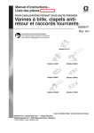
1
for normal levels of background
and trace illumination.
f
3. Observe the HV oscillator current. Normal current is approximately 650 mA to 800 mA.
Excessive current is >900 mA.
HV
DISABLE
CIRCUIT
4. If current is excessive, start
checking the following components in the following order:
pacitance-easiest way
to check is by substituting another diode (HP
part no. 1901-0028).
In most cases, the problem will be
found by this process, and with a
high level of confidence in the corrective action.
Partial conduction of
A15Ql-disconnect collector of A15Q1. If curr e n t is now n o r m a l
troubleshoot HV disable circuit.
If you did not observe excessive current, the problem is either intermittent or temperature related and
monitoring the current for a longer
period with the covers on will probably do the trick.
@Hew1lett-Packard 1982
Part No 5952-0112
-
WWW.HPARCHIVE.COM
.-
-
__
led for making microwave scameasurements with confidence.
tiled information is presented
Microwave Measuring Techniques - Applications information on scalar reflection and
transmission measurements, freauency, Dower, and noise figure
measurements. Includes tab1ilar
comparisons of accuracy and rel.r ._._
. ..__I--?_.
auve costs or
various
cecnniques.
Also includes a list of pert,inent
HP Application Notes.
-1.
0
oaxial & Waveguide Measurement Accesxies Catalog (HP Part No. 5952-8262)
0
om individual components
nple enough. Most scalar
P-..
rement tecnniques ror
amenor SWR are very straightforand well described i n the
ure. So it would seem all you
1
.
1
.
_LA_-
HP has introduced many microwave
measurement advances, both i n
hardware and in techniques. This
catalog brings together that technical a n d product information
2
BENCH BRIEFS
~
2
I -
Equipment Selection Tables Band-by-band listings of hardware model numbers required for
reflection a n d insertion loss
measurements in coax and waveguide.
Associated Instruments - Other
electronic equipment commonly
used i n microwave measuring
setups-signal generators, syn
thesizers, sweepers, spectrunn
analyzers, network analyzers
power meters and counters.
9
0
But, like a chain, a measuring system is only as strong as its weakest
link. You need components designed for measurement results-no
electrical or physical incompatibilities, no surprises. That's why HP
offers a broad line of measurement
components designed for just t h a t
results.
..-L
0
Coaxial and Waveguide Instrumentation Tables - A listing of
product model numbers by function vs. frequency range for coax
and waveguide.
Connectors - Information on
coaxial connectors and waveguide flanges. Includes comprehensive c h a r t of waveguide
specifications.
If you would like a copy of this catalog, contact your local HP Sales
and Service office.
NOVEMBER-DECEMBER 1982
WWW.HPARCHiVE.COM
Oscillosc ope Accessories
Probing In Perspective (HP Part No.
5952-1892)
For many years, oscilloscopes have
been the chief test and analysis instruments used by electronic engineers and technicians. I n recent
years, new techniques and components have extended oscilloscope
measurement capabilities to many
new applications. However, the oscilloscope is a useful measurement
instrument only if the test signal
can be accurately coupled to the
amplifiers. In many applications, the
voltage probe is the only practical
method to pick off and apply the
signal. With the increased bandwidths in today's scopes, one probe
cannot be used for all measurements. This application note provides an approach that will allow
you to select the best probe for most
commonly encountered oscilloscope
measurement situations. Major
areas covered are:
How to select the most accurate
scopdprobe for a particular measurement.
How to quickly evaluate a given
scopdprobe for its adequacy in a
particular measurement situation.
How to quickly estimate errors
caused by the probe.
'1
Almost any probdscope combination
can be used to view a waveform.
However, m a k i n g a c c u r a t e
measurements requires careful
attention to proper probe selection.
Since all probes inherently create
some error, the objective is to select
a probe that reduces the error to an
acceptable (or known) level. Proper
probe selection i n c r e a s e s t h e
confidence you c a n place i n
oscilloscope measurements. True,
part of your confidence comes from
knowing your scope, but the right
probe determines whether or not the
full accuracy potential of your
oscilloscope is realized.
If you would like a copy of this
catalog, contact your local H P Sales
and Service office.
More on Printed Circuit
Board Rework, Repair,
and Cleaning
If you found the article on reworking and cleaning printed circuit
boards interesting, there is more.
rrlarly
111UIt:
guuu up LIcal rrllcruucupt:
and SEM photographs-such
one below.
c
as the
If you are interested in learning
more on printed circuit board reliability, contact your nearest H P
sales or service office about the following video tapes.
Printed Circuit Board Reliability 36 min. HP part 90660R
Printed Circu:
liability - 25
ReilR
Analysis of Multilayer Ceramic Capacitors - 27 min. HP part 90662R
den drite (den’ drit), n. 1. Geol. a. a branching figure or marking, resembling moss or a
shrub or tree in form, found on or in certain
stones or minerals due to the presence of a
foreign material. b. any arborescent crystalline
growth. 2. Anat. the branching process of a
neuron which conducts impulses toward the cell.
See diag. under neuron.
Thls particular form of dendrlte was caused
by excesslve use of circuit cooler during
troubleshooting. The board surface was severely dlsturbed due t o the radlcal ternperature change. This created a fissure,
provldlng the gold a route to grow, following the path of least resistance between the
dlfferent potentlals of the adjacent traces.
The result Is a resistive short between the
two traces.
1
WWW.HPARCHIVE.COM
NOVEMBER-DECEMBER 1982
BENCH BRIEFS 3
HP-IB Verification Programs
Many Hewlett-Packard instruments with HP-IB capability have calculator-controlled programs available that can
save you considerable time in verifying instrument operation. Most programs are documented with instructions,
listing, flowchart, check points, etc. For more information on the programs listed below, contact your local HP office.
TAPE PART NO.
MODEL
PROGRAM D O C U M E N T A T I O N
30428
3045A
Network A n a l y z e r
Spectrum Analyzer
03042-90211
03045-10001
3047A
S p e c t r u m A n a l y z e r w:i t h
35601-10001 (984513)
35601-10011 (983614 )
35601A Manual
3560 1 A Manual
03050-90230
03050-90212
(98251!)
(9830A)
3050B Manual
3050B Manual
03052-90011
03052-10002
03052-10004
03052-10008
(9825A)
(9845B)
3052A
3052A
3052A
3052A
03054-10002
03054-10005
(9835A)
(9845B)
3054A Manual
3054A Manual
03335-10001
03437-10001
(9825A)
(9825A)
3335A Manual
3052A Manual
03455-10001
03455-10002
(98301i )
(98251
3052A Manual
3052A Manual
(Y03UA)
30546
Voltmeter System
3335
3437
izer
3455
3495
(9825A)
(9825A)
(9835A)
(9835B)
3042A Manual
3045A Manual
Manual
Manual
Manual
Manual
03495-10002
(98258)
3495A Manual
34956 Manual
u39y3-
I
uuu
I
3582A
3585A
Spectrum Analyzer
Spectrum Analyzer
03582-10001
03585-10001
(9825A)
(98258)
3582 Manual
3585 Manual
37201 A
37203A
HP-IB
HP-IB
37201-18100
37203-12101
(9825A)
(9825A)
37201 A Manual
372036 Manual
3745A
3745B
S e l . L e v e l Meas. S e t
S e l . L e v e l Meas. S e t
03745-1 8003 (9825A)
03745-1 8003 (9825A)
3745A/B-52
3745A/B-52
S e r v Note
S e r v Note
3747A
3747B
S e l . L e v e l Meas. S e t
S e l . L e v e l Meas. S e t
03745-18003
03745-18003
3747A/B-23
3747A/B-23
S e r v Note
S e r v Note
4
BENCH BRIEFS
Extender
Extender
NOVEMBER-DECEMBER 1982
(9825A)
(98258)
WWW.HPARCHIVE.COM
/7
3
5005B
5150A
Signature Multimeter
Thermal Printer
59300-10002 (85A)
59300-10001 (9825A)
5005B Manual
5050A-4 Serv Note
5312A
5312A
ASCII Interface (5300B)
HP-IB Interface Module
59300-10001 (9825A)
59300-10002 (85A)
5312A-2 Serv Note
5312A-4A Serv Note
5316A
53286
59300-10002 (85A)
Universal Cntr.
Universal Cntr.(Opts.011 , 59300-10001 (9825A)
020,021,030,031,040,041)
5316A-3A Serv Note
5128A-17 Serv Note
5328A
53286
Universal Cntr.(Opt.H99)
Universal Cntr.
(Opt. 096/H42)
5328A/H99 Manual
5328A/H42 M;
5328A
5328A
Universal Cntr. (Opts.011, 59300-10002 (85A)
020,021,030,031,040,041)
Universal Cntr.(military)
59300-10002 (85A)
5335A
Universal Cntr.
59300-10001 (9825A)
59300-10002 (85A)
5335A Manual
5335A-7B Serv Note
5340A
5341A
Frequency Cntr.(Opt.011)
Frequency Cntr.(Opt.Oll)
59300-10001 (9825A)
59300-10001 (9825A)
5340A-11 Serv Note
5341A Manual
53426
5342A
Microwave Cntr. (Opt.011)
Microwave Cntr.(Opts.002,
011)
59300-10001 (9825A)
59300-10002 (85A)
5342A Manual
5342A-32A Serv Note
5343A
5343A
Microwave Cntr. (Opt .011) 59300-10001 (9825A)
Microwave Cntr. (Opts.004, 59300-10002 (85A)
011)
5343A Manual
5343A-llA Serv Note
53445
5345A
Microwave Source Synchro.
Electronic Cntr.(Opt.011)
c
P
59300-10001 (98256)
59300-10001 (9825A)
59300-10002 (85A)
59300-10001 (9825A)
53288-33B Serv rior,e
5328A-34B Serv Note
53443 Manual
5345A-9A Serv Note
NOVEMBER-DECEMBER 1982
WWW.HPARCHIVE.COM
--~--___
~
-
I
-
BENCH BI
5345A
Electronic Cntr.(Opt.012)
5345A
59300-10001
59300-10002
(98258)
E l e c t r o n i c Cntr.(Opt.011)
5345A
E l e c t r o n i c Cntr.(Opt.012)
Channel C Plug-In
59300-10002
59300-10001
(85A)
5353A
(85A)
5345A-12A S e r v Note
5345A 19A S e r v N o t e
(9825A)
5345A-20A S e r v N o t e
53536-1 S e r v N o t e
5355A
4 GHz Frequency C n t r .
59300-10001
A u t o m a t i c F r e q g e n c y C n v t r . 59300-10001
(9825A)
(9825A)
5354A-6 S e r v N o t e
5355A Manual
5358A
5359A
Measurement S t o r . P l u g - i n
Time Synthesizer
59300-10001
59300-10001
(9825A)
(9825A)
5358A Manual
5359A Manual
53636
5363B
Time I n t e r v a l Probes
Time I n t e r v a l Probes
59300-10001
59300-10001
(9825A)
(9825A)
5363A-2 S e r v N o t e
5363B Manual
59300-10001
05420-69002
(9825A)
(9825A/B)
5370A-1A S e r v N o t e
Supplied with t a p e
5354A
Univ. Time I n t v . Cntr.
5370A
5420A/B D i g i t a l S i g n a l A n a l y z e r
5423A
59301A
S t r u c t u r a l Dynamics Ana.
ASCII/Parallel Cnvtr.
05420-69002 (9825A/B)
59300- 1000 1
Supplied with t a p e
59301-2 S e r v N o t e
59303A
59304A
Digital-to-Analog
Numeric D i s p l a y
59300-10001
59300-10001
593038-1 S e r v N o t e
59304A-1 S e r v N o t e
59306A
59307A
Relay Actuator
VHF S w i t c h
59300-10001
59300-10001
59306A-4 S e r v Note
59307A-3 S e r v N o t e
59308A
59309A
Timing G e n e r a t o r
D i g i t a l Clock
59300-10001
59300-10001
59308A-1 S e r v N o t e
59309A-3 S e r v Note
5931311
Analog-to-Digital C n v t r .
Multiprogmr. I n t e r f a c e
59300-10001
14551-13001
59313A Manual
59500A
6034A
69321B
Power S u p p l y
D/A Voltage Converter
06034-10002
14551-13001
06034-10002 K i t Manual
Supplied with t a p e
6940B
694 1 B
Multiprogmr.
Multiprogmr. Extndr.
14551-13001
14551-13001
Supplied with t a p e
Supplied with t a p e
6942A
69xxx
Multiprogmr.
M u l t i p r o g m r . P l u g - I n Cds.
14710-13001
14551-13001 (9825A)
Supplied i n classroom
Supplied with t a p e
7220
Graphics P l o t t e r
07220- 1 800 1 ( 9825A)
5010-2585
(85A)
( o r d e r from C P C )
5957-3862
(85A)
( o r d e r f r o m SDD)
Supplied with t a p e
Supplied with t a p e
6
BENCH BRIEFS
Cnvtr.
NOVEMBER-DECEMBER 1982
WWW.HPARCHIVE.COM
Supplied with t a p e
Supplied with t a p e
'1
7221
7
07221-18010
50 10-2585
Graphics Plotter
(264~)
(85A)
( o r d e r from CPC)
5957-3862
(85A)
( o r d e r from SDD)
Graphics Plo ter with
1 7 6 0 0 Module
4
R
Supplied with t a p e
Supplied with t a p e
Supplied with t a p e
( o r d e r f r o m CPC)
(85A)
( o r d e r f r o m SDD)
Supplied with t a p e
09872-1 8001
09872-18002
09872-1 8003
5010-2585
Graphics Plotter with
1 7 6 0 1 Module
(9825A)
(9835A)
(9845B)
(85A)
( o r d e r from CPC)
5957-3862
(85A)
( o r d e r f r o m SDD)
7225
"7
(85A)
( o r d e r from CPC)
5957-3862
(85A)
( o r d e r f r o m SDD)
with
with
with
with
tape
tape
tape
tape
Supplied with t a p e
Supplied with t a p e
Supplied with tape
Supplied with tape
Plotter/Printer
07245-1 800 1 ( 9 8 2 5 6 )
07245-18002 ( 9 8 3 5 / 4 5 )
Supplied with tape
Supplied with t a p e
7310
Graphics Printer
07310-18001
07310-18002
(9835)
Supplied with tape
Supplied with tape
7470
Graphics Plotter
5010-2585
(85A)
Supplied with tape
( o r d e r from CPC)
5957-3862
(85A)
( o r d e r f r o m SDD)
Supplied with t a p e
7585
Drafting Plotter
(2647)
(85A)
( o r d e r f r o m CPC)
5957-3862
(85A)
( o r d e r f r o m SDD)
Supplied with tape
(85A)
( o r d e r from C P C )
Supplied with tape
(85A)
Supplied with tape
5010-2585
5010-2585
Drafting Plotter
5957-3862
Supplied with t a p e
( o r d e r f r o m SDD)
'j
.
(9825A)
Supplied
Supplied
Supplied
Supplied
7245
7580
7
07220-18001
5010-2585
Graphics Plotter with
1 7 6 0 3 Module
Supplied with t a p e
07225-1 8002 ( 9 8 2 5 A )
07225-18003 ( 9 8 1 5 )
5010-2585
(85A)
5957-3862
7225
Supplied with t a p e
Supplied with t a p e
8160A
8409B
P r o g r a m m a b l e P u l s e Gen.
Network A n a l y z e r
08160-39910
11863-10004
(9825A)
(9835/45)
Supplied with tape
8409B,
11 863D Manual
8409C
8409D
Network A n a l y z e r
Network A n a l y z e r
11 863-10006
11 863-10005
(9845B)
(9826B)
8409C,
8409C,
11863F Manual
11 863E Manual
__
NOVEMBER-DECEMBER 1982
WWW.HPARCHIVE.COM
~ ~ - - -
1--_1_-
_ I _ _ _ _ _ _ I
_
I
P
-l_L--
l__
----
BENCH BRIEFS 7
_______
/1
one-half the line voltage in 220 or
240 volt AC applications. For 100
or 120 volt AC lines this is a neutral trace.
Safety- Related
Service Notes
Service Notes from HP relating to
personal safety and possible equipment damage are of vital importance t o our customers. To make
you more aware of these important
notes, they are printed on paper
with a red border, and the service
note number has a “-S” suffix. In
order to make you immediately
aware of any potential safety problems, we are highlighting safetyrelated service notes here with a
brief description of each problem.
Also, in order to draw your attention to safety-related service notes
on the service note order form at the
back of Bench Briefs, each appropriate number is highlighted by
being printed in color.
.
All 3325As in use in 220- or 240volt AC applications must be returned to the closest HP Service
Center for the proper corrective action. Users operating 3325As from
100- or 120-volt AC lines have two
options: 1) return the unit to HP
for service or 2) order the SafetyService Note 3325A-llA-S with the
order form at the rear of Bench
Briefs and perform the steps described in the note.
3
”7
~~
I
posed BNC connector shells on generators with serials 1748A00101
through 1748A06800. A trace on the
underside of t h e A2 PC board
(03325-66502) could pass less than
0.5mm from the edge of the instrument subchassis. This trace carries
For one thing they are free.
A potential shock hazard may exist
in units operated from 220- or 240volt AC lines. The spacing between
circuit board traces on the power
supply assembly does not comply
with IEC 348 requirements. Refer
to the following serial numbers to
see if your instrument requires corrective action.
3
What Do Service Notes Say?
Service Notes recommend modifications to instruments to increase
reliability, improve performance,
or extend their usefulness.
Notes are used to inform
WWW.HPARCHIVE.COM
The AC and NEUTRAL wires are
reversed at the rear panel power
module on units with serial numbers 2141A00592 and below. As a
result, the line fuse is located in the
NEUTRAL side of the power line.
This wire reversal does not affect
the operation of the unit, and under
normal conditions, will not be hazardous to the operator. However, if
a n internal AC short to chassis
ground occurs and the external
ground path has been broken, the
chassis would be at AC potential
with no fuse.
To correct the problem, exchange the
AC and NEUTRAL wires at the AC
power module inside the rear panel.
For detailed instructions, order
Safety-Service Note 6034A-5-S with
the order form at the rear of Bench
Briefs.
3336A 1930A00409 through
1930A00530
3336B 1931A00396 through
1931A00570
3336C 1932A00276 through
1932A00340
@
For another they provide an aftersales support link to HewlettPackard for a continuous flow of
service-related information about
your instrument.
6034A System Power
Supply
3336A/B/C Synthesizer/
Level Generator
3325A Synthesizer/
Function Generator
A shock hazard may exist on all ex-
If your generator falls into the above
group, use the order form at the rear
of Bench Briefs and order SafetyService Note 3336AIBIC-5A-2,which
will tell you to return your unit to
the nearest HP Service Center for
repair.
you of a revised adjustment procedure, recommended parts replacements, and new troubleshooting procedures.
Safety Service Notes communicate potentially hazardous conditions related t o the use of
instruments.
NOVEMBER-DECEMBER 1982 BENCH BRIEFS 9
What Are The Benefits To Me?
You can create a history file on each
HP instrument you own. Service
Notes describe modifications to instruments out in the field and are
the only way you have of keeping
your operating and service manual
up-to-date.
-- __- HOW u o I Obtain
-
Inside Bench Briefs is an abstract of
all the current Service Notes issued
Over
the last 213months' At
- the
A.
Y""lL
ALL
Y l l V
UU""lU""
N\.JA,)IL,I
i
l
I I( / I I \
Rplfy6
LII 1uhdu;L
iI
ll""
L
L
L:
*
"
I
of
model
number
instrument.
"IIV
your
3. If You want the note (01notes many times there is more than
One),
check the appropriate
On the Order
form and
mail i t to one of the listed
addresses.
Library
U
n
Need Any Service
Notes?
Thev're free!
Subscription
Library
C--L---:-A:--
Are Back Issues Available?
yes! A library of all service notes
ever issued for most HP measuremerit and test instruments is available on microfiche. In addition, a
library of operating and service
manuals is also available on microfiche. These two libraries and
updating subscription service are
4 V V C l t L AG V U L l M t I ttl
I
rm
I
available from Hewlett-Packard under the following part numbers.
- - .
Y e r v i C e Notes
I
2. Read the abstract to get an idea
of what the note is about.
ouuacrlpLlurl
Library
Subscription
Manuals only
5951-6505
Manuals only
5081-5812
Service Notes only
5951-6511
0--2-- h T - A - -
5951-6517
Manuals & Notes
5951-6523
Manuals & Notes
5951-6529
Please contact your nearest H P
Sales or Service office for prices and
ordering details.
1805A DUAL CHANNEL VERTICAL
AMPLIFIER
400EEL-2B. All serials. Recommended replacement
parts.
400E/EL-13. W E serials 1208A 29593 and below;
400EL serials 2214A 28523 and below. (Option
H99 instruments only.) Improved Option H99 Line
indicator light operation.
3060A-51. All serials. New Volume IC-CCD Manual.
AC VOLTMETER
.---.-. - 4OOF/FL
.--- serials
. . UY5UA
---- 14305 ana. .below;
.
3325A SYNTHESIZER/FUNCTION
GENERATOR
~wI-/I-L-I.
4001-
~
.
4MFL Serials 2213A 14250 and below. (Option
H99 instruments only.) Improved Option H99 Line
indicator light operation.
400GL AC VOLTMETER
400GL-3. 400GL serials 0943A 03870 and below.
(Option H99 instruments only.) Improved Option
H99 Line indicator light operation.
placement for A9T1.
3060A CIRCUIT TEST SYSTEM
3325A-11A-S. Serials 1748A00101 through
1748A06800. Notification of potential safety
hazard.
3:325A-12. Serials 1748A-05825 and below. Procedure for installing Rev E power supply.
3336A/B/C SYNTHESIZER/LEVEL
GENERATOR
~ I I C A
-.:-4-.
L u r v PI u--tn. oooun
a i r iaia pr IVI tu
~ I C A I P ~ P
AA
Here's the latest listing of Service
Notes. They recommend modifications to Hewlett-Packard instrureliability,
e, or extend
652A TEST OSCILLATOR
652A-6. All serials. Replacement procedure for the
range switch (Sl).
13108 GRAPHICS GENERATOR SYSTEM
13108-2. All serials. Explanation of Blue Stripe Board
Exchange Program.
1311B GRAPHICS GENERATOR SYSTEM
1311B-6. All serials. Explanation of Blue Stripe Board
Exchange Program.
the rear of
the notes that
ents.
it
--'I--
ne1 v1ce I Y u L e s U l l l Y
4oanrnnAnn.
I =ilvnVv.tu~,
33368 serials prior to 1931A00396; 33360 serials
prior to 1932A00276. Procedure for replacing
3336A/B/C Rev A, Rev B, Rev C or Rev D pow&
supplies (A2 PC board) with the 3336A/B/C Rev E
power
supply.
^^^^.
,-,..
-.--..
.
xdmA/tvL-w+s.X ~ Aserials iYH)AWU~UY tnrougn
1930A00530; 33368 serials 1931A00396 through
1931AOO570; 33366 serials 1932A00276 through
1932A00340. Trace spacing discrepancy in Revision D power supply-22OV/24OV applications.
3336A/B/C-9. Spare Parts Service Kit.
-. - ----.
~
---.-
13178 GRAPHICS GENERATOR SYSTEM
3437A SYSTEMS VOLTMETER
13178-2. All serials. Explanation of Blue Stripe Board
Exchange Program.
3437A-8. All serials. Parts recommendation for on-site
repair.
13218 GRAPHICS GENERATOR SYSTEM
3455A DIGITAL VOLTMETER
!low. Modification to
shock during failure
13218-2. All serials. Blue Stripe Board Exchange
Program.
3455A-20A. All serials. 3455A Service Kit 0345569801 replaced by Service Kit 44055C.
1340A X-Y DISPLAY
3456A DIGITAL VOLTMETER
'IGURE METERS
1340A-5. Serials 2038 and below. Modification to improve LVPS performance.
3456A-18. All serials. 3456A Service Kit 03456-69801
replaced by Service Kit 440568.
3456A-14. Serials 2201A06299 and below. Modification to enhance analog circuitry.
3456A-17. All serials. 3456A Service Kit 03456-69800
replaced by Service Kit 44056A.
:OPE
1940A03366 to
s 1930A03371 to
event the diode cur320 from shorting to
n
, rack mount ver-
1351A/S GRAPHICS GENERATOR SYSTEM
JRCE
1351
All serials. Explanation of Blue Stripe
Board Exchange Program.
1351A-1: All serials. Explanation of Blue Stripe Board
Exchange Program.
1351s GRAPHICS GENERATOR SYSTEM
!037A01457. ModifiIO MHz oscillation.
1645A DATA ERROR ANALYZER
1645A-8. All serials. Resistors incorrectly loaded on
10388A interface.
EMBER-DECEMBER 1982
WWW.HPARCHIVE.COM
3476NB DIGITAL MULTIMETER
3476A-2A. All Serials. General SeWiCe infOnllatiOn
regarding replacement parts for 3476A.
34768-6. All serials. General service information
regarding replacement parts for 34768.
I
35558 TRANSMISSION AND NOISE
MEASURING SET
35558-5. Serials 0992A03536 and below. Improved
power supply.
3586A/B/C SELECTIVE LEVEL METER
3586A/B/C-9. Field replacement kits for the A50 Step
Loop and A51 Summation Loop assemblies.
3586A/B/C-10. All serials. Announcement of service
spare parts kit for HP model 3586A/B/C Selective
Level Meter.
3711A IF/BB TRANSMITTER
3711-2. All serials. Part number change for IF
Attenuator.
3712A IF/BB RECEIVER
3712-5. All serials. -15V rail fuse blowing
(intermittently).
3712-6. All serials. Part number change for IF
Attenuator.
37308 DOWN CONVERTER.
37308-2. All serials. Part number change for OPT 010
IF Attenuator.
37708 TELEPHONE LINE ANALYZER
37708-26. All serials. Preferred replacement of power
supply switching transistors HP part number
1854-0665.
3779A/B/C PRIMARY MULTIPLEX
ANALYZER
3779A-23. All serials. Service accessories for performance tests.
3779A-24. All serials. Preferred replacement of ROMs
on A23.
37798-25. All serials. Service accessories for performance tests.
37798-26. All serials. Preferred replacement of ROMs
on A23.
3779C-5. All serials. Service accessories for performance tests.
3779D-5. All serials. Service accessories for performance tests.
3785NB JITTER GENERATOR AND
RECEIVER
3785A-2. Serials 2226U 00210 and below. Improvement in synthesizer buffer loading.
37856-2. Serials 2216U 00130 and below. Improvement in synthesizer buffer loading.
3964A INSTRUMENTATION TAPE
RECORDER
3964A-19. All serials. Mislabeled FM data PCAs.
3968A INSTRUMENTATION TAPE
RECORDER
5180A-2. Serials 2210A00220 and below. Modifications to Z OUT, +15V regulator and TRIG OUT
circuits on the A25 rear panel assembly.
5180A-3. Serials 2044A00200 and below. Modification
to prevent possible oscillation of the +15V regulator circuit on A25 rear panel assembly.
5180A-4. Serials 2224A00310 and below. Modification
to prevent possible noise problems associated with
the TRIG OUT circuit on the A25 rear panel
assembly.
5180A-5. Serials 221OAOO211 and below. Modification
to A8 and A9 high speed memory assemblies to
correct bad data points.
5180A-6. Serials 2220A00300 and below. Input
amplifier static protection and frequency bandwidth
modifications.
5180A-7. All serials. AC line protections (mains) fuse
change.
5180A-9. All serials. ROWEPROM replacement
strategy.
5335A UNIVERSAL COUNTER
5335A-15. Serials 2224 and below. Modification to
improve the performance of the X10 Attenuator
Circuitry in Option 040.
5342A MICROWAVE FREQUENCY
COUNTER
5343A MICROWAVE FREQUENCY
COUNTER
5343A-14. Serials 2104A00335 and below. Replacement for A10U6 Divide-by-N Assemblies.
5343A-15. Serials 2204A and below. ROM change
corrects miscounts and limit errors in manual
mode.
5343A-16. Serials 2228A and below. Resistors
required when changing A10U2 Divide-by-N
Assemblies.
5343A-17. Serials 2232A00845 and below. A1 8 Time
Base Buffer and A21 Power Supply Assembly
Compatibility.
53448 MICROWAVE SOURCE
SYNCHRONIZER
5451C FOURIER ANALYZER SYSTEM
5451 C-06. All serials. 54440A Filter adjustment
procedure.
5451C-07. All serials. 54420A DAC adjustment
procedure.
6034A POWER SUPPLY
6034A-5-S. Serials 2141A-00592 and below. Reversed AC and neutral (ACC) at power module.
4935A-7. Serials 2208A and lower. Modification
required to make new transformer backward
compatible.
4935A-8. Serials 2208 and below. Modification to improve reliability of output level control.
8447C-1. Serials 1937A and below. Modificationkit for
replacement amplifier.
50058 SlGNATlIRE MULTIMETER
5005B-1. Serials listed ir1 text. Function select error
when returning to remote.
5046A DIGITAL IC TEST SYSTEM
__
.- which
....
..
r _ U _ _
5046A-2. All serials. List' nf
_. IC text oroarams
have been revised.
5180A WAVEFORM RECORDER
51MA-1, All serials. Improved adjustment procedures
for XYZ display circuit.
8566A SPECTRUM ANALYZER
8566A-18. Serials 2139A and below. Modifications to
A13 HP-IB interface.
8569A SPECTRUM ANALYZER
8569A-7. Serials 2113A00220 and below. Suppression of 70 kHz sidebands.
8672A SYNTHESIZED SIGNAL GENERATOR
8672A-10A. All serials. Option 008 Retrofit for greater
power output.
8683A SIGNAL GENERATOR
8683A-1. Serials 2208A and below. Improvement of
pulse overshoot.
897OA-1. Serials 21 16A and below. Improvement of
power measurement by eliminating oscillation.
8970A-2. All serials. Recommended modification upon
A8Q1 replacement.
64000 LOGIC DEVELOPMENT SYSTEM
64000-OD. Service note index.
64100A LOGIC DEVELOPMENT STATION
64100A-13. All serials. Washing with harsh soaps or
solvents will cause the water base paint to be
removed.
64110A LOGIC DEVELOPMENT SYSTEM
MAINFRAME
641 10A-2. All serials. Incorrect power supply failure
LED indications.
641 10A-3. All serials. Low line trip adjustment.
64110A-4. Serials 2225A-00293 and before. Overpower shutdown.
64110A-5. All serials. Washing with harsh soaps or
solvents will cause the water base paint to be
removed.
64155A-1. 64155A wide address memory controller;
board numbers 64155-66501. Modification to allow
addressing of 2 megabytes of emulation memory.
53448-1. Serials listed in text. Board change corrects
remote command being ignored after local lockout.
4935A TRANSMISSION IMPAIRMENT
MEASURING SET
4940A-16. Serials 1401A and below. (New prefix
2240A with 0837-0252.) Power supply improvement and mini repair.
8565A SPECTRUM ANALYZER
8565A-16A. All serials. Log Amplifier adjustment.
8970A NOISE FIGURE METER
5342A-37. Serials 2104A04095 and below. Replacement for A10U6 Divide-by-NAssemblies.
5342A-38. Serials 2244A06615 and below. A18 Time
Base Buffer and A21 Power Supply Assembly
compatibility.
5342A-39. Serials 2228A and below. Resistors
required when changing A10U2 Divide-by-N
Assemblies.
3968A-21. All serials. Mislabeled FM data PCAs.
4940A TRANSMISSION IMPAIRMENT
MEASURING SET
HP Part Number 08553-60059 for HP 8559A compatibility with HP 853A Spectrum Analyzer Display.
8559A-12. Serial prefix 2208A and below. "Anticrush" Drive Hub and Reference Level knob.
8559A-13. Serials 2208A and below. Improved Log
Amplifier Assembly.
8447C SERIES AMPLIFIERS
8557A SPECTRUM ANALYZER
3557A-4. Serials 2106A and below. Modification Kit
HP Part Number 00853-60057 for HP 8557A compatibility with HP 853A Spectrum Analyzer Display.
8557A-5. Serials 2106A and below. Improved Log
Amplifier Assembly.
64
I.
d
e
64215A-1. 64215A 6809 Emulator Subsystem.
Emulator Pod serial prefix numbers 2250 and
above. Parts list for "user cable with active
assembly."
64262A-3. 64262A 8048 Emulator Subsystem.
Emulator Pod serial prefix numbers 2240 and
above. Parts list for "user cable with active
assembly."
645XX PROM PROGRAMMER
85588 SPECTRUM ANALYZER
85588-16A. All serials. Changing standard 8551BB into
75 ohm Option 001 or 002.
85586-23.
2145A and below. Modificaition Kit
.~~~~
~.Serials
-~
HP Part Number 00853-60058 for HP 855813 compatibility with HP 853A Spectrum Analyzer DIisplay.
85588-24. Serials 2142A ana below. improved Log
Amplifier Assembly.
~~
8559A SPECTRUM ANALYZER
8559A-11. Serials 2208A and below. Modification Kit
WWW.HPARCHIVE.COM
642XX EMULATOR SUBSYSTEM
64202-38. 64202A 8080 Emulator Subsystem.
Emulator Pod with repair numbers 2013A00420
and below. User wait state failures.
64203A-7. 64203A 8085 Emulator Subsystem.
Emulator Pod serial prefix numbers 2241 and
above. Parts list for "user cable with active
64500s-2. 645008 Positive PROM programmer. Serial prefix 1924A. ID code failure.
64502A-2.64502A programmer module. Verify failure.
64621A STATE ANALYSIS CONTROL
BOARD
64621A-1. Serial prefix 2144A. -12VDC in Clock/
Preprocessor Control cable.
85650A QUASI-PEAK ADAPTER
85650A-3. All serials. Correct AC mains fuses.
NOVEIMBER-DECEMBER 1982
BENCH BRIEFS 11
If you want service notes, ,please
check the amwopriate boxes below
and return, this -form separately to
one of the following addresses.
'
For European customers (ONLY)
Name
Hewlett-Packard
Central Mailing Dept.
P. 0. Box 529
Van Hueven Goedhartlaan 121
AMSTELVEEN-1134
Netherlands
Firm
Hewlett-Packard
1820 Embarcadero Road
Palo Alto, California 94303
0 8672A-1OA
0 50058-1
0 5451C-06
0 5451C-07
0 5046A-2
0 5180A-1
0 518OA-2
0 6134A-5-S
0 8447C-1
0 8557A-4
0 641OOA-13
0 64110A-2
0 641lOA-3
0 518OA-3
0
0
0
0
0
0
0
0
0
4OOF/FL-7
400QL-3
652A-6
13108-2
13118-6
0 3456A-18
0 3456A-14
0 3456A-17
0
0
0
0
0
13178-2
13218-2
1340A-5
1351A-1
1351S-1A
0
0
0
0
0
35558-5
3586A/B/C-9
3586A/B/C-10
3711-2
3712-5
0 494OA-16
0
0
0
0
0
1645A-8
1805A-2
306OA-51
0
0
0
0
0
3712-6
37308-2
37708-26
3779A-23
3779A-24
?
4-11A-S
3325A-12
0 37858-2
0
0
0
0
0 3476A-2A
0 34768-6
ZIP
0 5343A-14
0 5343A-15
0 5343A-16
0 5343A-17
0 5344S1
0 3336A/B/CdA
0 3455A-20A
State
0 8559A-12
0 8559A-13
0 8565A-l6A
37798-25
37798-26
3779c-5
3779D-5
3785A-2
140T-1C-S
3408/342A-5
3468-3
400E/EL-28
400E/EL-13
0 3336A/B/C-9
0 3437A-8
city
5180A-9
5335A-15
5342A-37
5342A-38
5342A-39
0
0
0
0
0
0
0
0
0
0
333riA/R/C-5A-S
Address
3964A-19
3968A-21
4935A-7
4935A-8
0 5180A-4
0 518OA-5
0 5180A-6
0 5180A-7
I
0
0
0
0
0
0 8566A-16
0 8569A-7
0
0
0
0
645OOA-2
64502A-2
64612A-1
8565OA-3
0 8683A-1
0 697OA-1
0 897OA-2
0 64000-00
0 64110A-4
0 6411OA-5
c
0 64155A-1
0 64202-38
8557A-5
85588-16A
85588-23
85588-24
0 8559A-11
Please photocopy this order form if you do not
wan1 to cul off the page
0 64262A-3
0 64203A-7
0 64213A-1
0 64215A-1
I
HEWLET-PACKARD COMPANY
Bulk Rate
1820 Ernbarcadero Road
Palo Alto, California 94303
U S . Postage
BENCH BRIEFS
Sunnyvale. CA.
NOV-DEC 1982
Volume 22 Number 5
Service information from
Hewiett-Packard Company
Permit No.
To obtain a qualification form for a free
subscription, send your request to the
above address.
Reader comments or technical article
contributions are welcomed.
Please send them to the
Bench Briefs Editor.
Editor: Jim Bechtold
Hewlett-Packard
690 E. Middlefield Rd.
Mt. View, CA 94042
OOLZ
O€
A I 1 7 l&nS l S V I
All rights reserved Permission IO repint Bench Briefs granted upon wnnen request lo the Editor
12
BENCH BRIEFS
r
3 33dPFL313Ld333
NOVEMBER-DECEMBER 1982
WWW.HPARCHIVE.COM
Printed in U S A .