1
Lüftungsluken / Notausstiegsluken
Ventilation Hatches / Emergency Exit Hatches
Trappes d’aération / Trappes issues de secours
Botole di ventilazione / Botole di salvataggio
Betriebsanweisung
Operating instructions
Manuel de service
Istruzioni per I’uso
BUS TOP K
BUS TOP Solar
BUS TOP C
01/2001
Ident Nr. 66550C
Inhvz_d_neu.fm Seite I Donnerstag, Januar 25, 2001 9:06 AM
BUS TOP K / SOLAR / C
Inhalt
1
1.1
1.1.1
1.1.2
1.1.2.1
1.1.2.2
1.2
1.2.1
1.3
1.4
1.4.1
1.4.1.1
1.4.1.2
1.4.2
Allgemeine Beschreibung........................... 1
Bus Top K ...................................................... 4
Manuelle Ausführung..................................... 5
Elektrische Ausführung.................................. 5
Bus Top K / Solar........................................... 5
Bus Top C...................................................... 5
Bus Top Solar ................................................ 6
Merkmale des Bus Top Solar ........................ 7
Bus Top C...................................................... 8
Sicherheitstechnische Baugruppen ............... 8
Notbetätigung ................................................ 8
Bus Top K / Solar........................................... 8
Bus Top C...................................................... 9
Einklemmschutz (nur Bus Top K / Solar,
elektrisch und Bus Top C) ............................. 9
1.4.3 Einbruchsicherung
(nicht bei Notausstiegsluke und Bus Top C).. 9
1.5
Optionale Baugruppen................................. 10
1.5.1 Verriegelungsanzeige
(nur Bus Top K / Solar) ................................ 10
1.5.2 Deckelstellungsanzeige ............................... 10
1.5.2.1 Bus Top K / Solar, elektrisch ....................... 10
1.5.2.2 Bus Top C.................................................... 10
1.5.3
1.5.3.1
1.5.3.2
1.5.4
Antriebsnotbetätigung .................................
Bus Top K / Solar, elektrisch .......................
Bus Top C ...................................................
Regensensor
(nur Bus Top K / Solar, elektrisch)...............
Komfortschließung
(nur Bus Top K / Solar, elektrisch)...............
10
10
10
12
12
13
2.4.1
2.4.2
Bedienung ..................................................
Lüftungsfunktionen Bus Top K, manuell......
Lüftungsfunktionen, elektrisch .....................
Funktion des Regensensors
(nur Bus Top K / Solar)................................
Notbetätigung ..............................................
Verriegelung des Außengriffs
(nur Bus Top K / Solar)................................
Manuelle Verriegelung ................................
Elektrische Verriegelung..............................
3
3.1
3.2
3.2.1
Wartung / Inspektion / Servicearbeiten .... 16
Wartung ....................................................... 16
Inspektion .................................................... 16
Überprüfung der Verriegelung ..................... 16
1.5.5
2
2.1
2.2
2.2.1
2.3
2.4
11
11
13
14
14
14
15
I
Inhvz_d_neu.fm Seite II Donnerstag, Januar 25, 2001 9:06 AM
BUS TOP K / SOLAR / C
Inhalt
3.3
3.3.1
3.3.1.1
3.3.1.2
3.3.2
Servicearbeiten ...........................................
Einsetzen des Deckels nach Notbetätigung
Bus Top K / Solar........................................
Bus Top C ...................................................
Prüfung des eingesetzten Deckels .............
17
17
17
17
17
4
4.1
4.1.1
4.1.2
4.1.3
4.2
4.3
4.4
Maßnahmen bei Störungen......................
Allgemeines ................................................
Bus Top K / Solar, elektrisch.......................
Bus Top Solar (Lüfter).................................
Bus Top C ...................................................
Elektrische Fehler .......................................
Systemschaltung Bus Top K / Solar ...........
Systemschaltung Bus Top C.......................
18
18
18
18
18
19
20
22
5
5.1
5.2
5.3
Technische Daten .....................................
Bus Top K ...................................................
Bus Top Solar .............................................
Bus Top C ...................................................
23
23
24
24
II
Inhvz_gb_neu.fm Seite III Donnerstag, Januar 25, 2001 9:07 AM
BUS TOP K / SOLAR / C
Contents
1
1.1
1.1.1
1.1.2
1.1.2.1
1.1.2.2
1.2
1.2.1
1.3
1.4
1.4.1
1.4.1.1
1.4.1.2
1.4.2
General Description................................... 25
Bus Top K .................................................... 28
Manual Type ................................................ 29
Electrical Type ............................................. 29
Bus Top K / Solar......................................... 29
Bus Top C.................................................... 29
Bus Top Solar .............................................. 30
Features of Bus Top Solar........................... 31
Bus Top C.................................................... 32
Safety Relevant Assemblies ........................ 32
Emergency Operation.................................. 32
Bus Top K / Solar......................................... 32
Bus Top C.................................................... 33
Trap Protection (only Bus Top Solar,
electrical and Bus Top C) ............................ 33
1.4.3 Antiburglar Protection (not for
emergency exit hatch and Bus Top C) ........ 33
1.5
Optional Assemblies .................................... 34
1.5.1 Locking Indication
(only Bus Top K / Solar)............................... 34
1.5.2 Cover Position Indication ............................. 34
1.5.2.1 Bus Top K / Solar, electrical ........................ 34
1.5.2.2 Bus Top C.................................................... 34
1.5.3
1.5.3.1
1.5.3.2
1.5.4
1.5.5
2
2.1
2.2
2.2.1
Drive Emergency Operation ........................
Bus Top K / Solar, electrical ........................
Bus Top C ...................................................
Rain Sensor
(only Bus Top K / Solar, electrical) ..............
Comfort Closure
(only Bus Top K / Solar, electrical) ..............
34
34
34
35
35
36
36
37
2.4.1
2.4.2
Operation ...................................................
Ventilation Functions Bus Top K, manual....
Ventilation Functions, electrical ...................
Function of Rain Sensor
(only Bus Top K / Solar) ..............................
Emergency Operation .................................
Locking of Outside Emergency Handle
(only Bus Top K / Solar) ..............................
Manual Locking ...........................................
Electrical Locking ........................................
3
3.1
3.2
3.2.1
Maintenance / Inspection / Servicing.......
Maintenance ................................................
Inspection ....................................................
Inspection of Locking Mechanism ...............
40
40
40
40
2.3
2.4
37
38
38
38
39
III
Inhvz_gb_neu.fm Seite IV Donnerstag, Januar 25, 2001 9:07 AM
BUS TOP K / SOLAR / C
Contents
3.3
3.3.1
3.3.1.1
3.3.1.2
3.3.2
Servicing ..................................................... 41
Fitting of Cover after Emergency Operation 41
Bus Top K / Solar........................................ 41
Bus Top C ................................................... 41
Check of Cover Placement ......................... 41
4
4.1
4.1.1
4.1.2
4.1.3
4.2
4.3
4.4
Troubleshooting........................................
General .......................................................
Bus Top K / Solar, electrical........................
Bus Top Solar (Fan)....................................
Bus Top C ...................................................
Electrical Failure .........................................
System Circuit Bus Top K / Solar................
System Circuit Bus Top C...........................
5
5.1
5.2
5.3
Technical Data........................................... 47
Bus Top K ................................................... 47
Bus Top Solar .............................................. 48
Bus Top C ................................................... 48
IV
42
42
42
42
42
43
44
46
Inhvz_frz_neu.fm Seite V Donnerstag, Januar 25, 2001 9:06 AM
BUS TOP K / SOLAR / C
Sommaire
1
1.1
1.1.1
1.1.2
1.1.2.1
1.1.2.2
1.2
1.2.1
Description générale ................................. 49
Bus Top K .................................................... 52
Exécution manuelle ..................................... 53
Exécution électrique .................................... 53
Bus Top K / Solar......................................... 53
Bus Top C.................................................... 53
Bus Top Solar .............................................. 54
Caractéristiques du modèle
Bus Top Solar .............................................. 55
1.3
Bus Top C.................................................... 56
1.4
Sous-groupes de sécurité technique ........... 56
1.4.1 Dispositif d’ouverture de secours................. 56
1.4.1.1 Bus Top K / Solar......................................... 56
1.4.1.2 Bus Top C.................................................... 57
1.4.2 Dispositif anti-coinçage
(uniquement Bus Top K / Solar,
à commande électrique et Bus Top C) ........ 57
1.4.3 Dispositif de protection
contre les effractions (non disponible
pour la trappe de secours et Bus Top C)..... 57
1.5
Sous-groupes optionnels ............................. 58
1.5.1 Affichage du verrouillage
(uniquement Bus Top K / Solar) .................. 58
1.5.2
1.5.2.1
1.5.2.2
1.5.3
1.5.3.1
1.5.3.2
1.5.4
1.5.5
2
2.1
2.2
2.2.1
2.3
2.4
2.4.1
2.4.2
Indication de la position du coffrage ............
Bus Top K / Solar, à commande électrique .
Bus Top C ...................................................
Entraînement du dispositif de secours ........
Bus Top K / Solar, à commande électrique .
Bus Top C ...................................................
Capteur anti-pluie (uniquement pour
Bus Top K / Solar, à commande électrique)
Fermeture confort (uniquement pour
Bus Top K / Solar, à commande électrique)
58
58
58
58
58
58
Commande .................................................
Fonctions d’aération Bus Top K,
à commande manuelle ................................
Fonctions d’aération,
commande électrique ..................................
Fonction du capteur anti-pluie
(uniquement Bus Top K / Solar) ..................
Dispositif d’ouverture de secours ................
Verrouillage de la manette extérieure
(uniquement Bus Top K / Solar) ..................
Verrouillage manuel ....................................
Verrouillage électrique.................................
60
59
59
60
61
61
62
62
62
63
V
Inhvz_frz_neu.fm Seite VI Donnerstag, Januar 25, 2001 9:06 AM
BUS TOP K / SOLAR / C
Sommaire
3
Maintenance / Inspections /
Travaux de dépannage .............................
3.1
Maintenance ...............................................
3.2
Inspections..................................................
3.2.1 Vérification du verrouillage..........................
3.3
Travaux de réparation.................................
3.3.1 Pose du coffrage après une ouverture
d’urgence ....................................................
3.3.1.1 Bus Top K / Solar........................................
3.3.1.2 Bus Top C ...................................................
3.3.2 Vérification du coffrage
après son installation ..................................
4
4.1
4.1.1
4.1.2
4.1.3
4.2
4.3
4.4
VI
64
64
64
64
65
65
65
65
65
Mesures à prendre en cas de mauvais
fonctionnement ......................................... 66
Généralités.................................................. 66
Bus Top K / Solar, à commande électrique 66
Bus Top Solar (ventilateur ......................... ) 66
Bus Top C ................................................... 66
Pannes électriques ..................................... 67
Schéma des connexions Bus Top K / Solar 68
Schéma des connexions Bus Top C........... 70
5
5.1
5.2
5.3
Caractéristiques techniques.....................
Bus Top K ....................................................
Bus Top Solar ..............................................
Bus Top C....................................................
71
71
72
72
Inhvz_ital_neu.fm Seite VII Donnerstag, Januar 25, 2001 9:07 AM
BUS TOP K / SOLAR / C
Indice
1
1.1
1.1.1
1.1.2
1.1.2.1
1.1.2.2
1.2
1.2.1
1.3
1.4
1.4.1
1.4.1.1
1.4.1.2
1.4.2
1.4.3
1.5
1.5.1
1.5.2
Descrizione generale................................. 73
Bus Top K .................................................... 76
Modello manuale ......................................... 77
Modello elettrico........................................... 77
Bus Top K / Solar......................................... 77
Bus Top C.................................................... 77
Bus Top Solar .............................................. 78
Caratteristiche del Bus Top Solar ................ 79
Bus Top C.................................................... 80
Elementi di sicurezza tecnica ...................... 80
Azionamento d’emergenza .......................... 80
Bus Top K / Solar......................................... 80
Bus Top C.................................................... 81
Protezione contro schiacciamento
(solo Bus Top K / Solar, elettrico
e Bus Top C)................................................ 81
Protezione contro furto
(non per botola di salvataggio
e Bus Top C)................................................ 81
Componenti optional.................................... 82
Visualizzazione di bloccaggio
(solo Bus Top K / Solar)............................... 82
Visualizzazione posizione del coperchio ..... 82
1.5.2.1 Bus Top K / Solar, elettrico..........................
1.5.2.2 Bus Top C ...................................................
1.5.3 Azionamento d’emergenza
del motore ...................................................
1.5.3.1 Bus Top K / Solar, elettrico..........................
1.5.3.2 Bus Top C ...................................................
1.5.4 Sensore antipioggia
(solo Bus Top K / Solar, elettrico)................
1.5.5 Chiusura di comfort
(solo Bus Top K / Solar, elettrico)................
2
2.1
2.2
2.2.1
2.3
2.4
2.4.1
2.4.2
Comando ....................................................
Funzioni di ventilazione
Bus Top K, manuali .....................................
Funzioni di ventilazione,
elettriche ......................................................
Funzione del sensore antipioggia
(solo Bus Top K / Solar) ..............................
Azionamento d’emergenza..........................
Bloccaggio della maniglia esterna ...............
(solo Bus Top K / Solar) ..............................
Bloccaggio manuale ....................................
Bloccaggio elettrico .....................................
82
82
82
82
82
83
83
84
84
85
85
86
86
86
86
87
VII
Inhvz_ital_neu.fm Seite VIII Donnerstag, Januar 25, 2001 9:07 AM
BUS TOP K / SOLAR / C
Indice
3
Manutenzione / ispezione /
interventi di assistenza ............................
3.1
Manutenzione .............................................
3.2
Ispezione.....................................................
3.2.1 Controllo del bloccaggio..............................
3.3
Interventi di assistenza ...............................
3.3.1 Inserire il coperchio dopo
l’azionamento d’emergenza ........................
3.3.1.1 Bus Top K / Solar........................................
3.3.1.2 Bus Top C ...................................................
3.3.2 Controllo del coperchio inserito...................
4
4.1
4.1.1
4.1.2
4.1.3
4.2
4.3
4.4
VIII
Misure in caso di anomalie ......................
In generale ..................................................
Bus Top K / Solar, elettrico .........................
Bus Top Solar (Ventilatori)..........................
Bus Top C ...................................................
Errori elettrici...............................................
Commutazione del sistema
Bus Top K / Solar........................................
Commutazione del sistema Bus Top C.......
88
88
88
88
89
89
89
89
89
90
90
90
90
90
91
92
94
5
5.1
5.2
5.3
Specifiche tecniche ...................................
Bus Top K ....................................................
Bus Top Solar ..............................................
Bus Top C....................................................
95
95
96
96
Kap_d_neu.fm Seite 1 Donnerstag, Januar 25, 2001 9:07 AM
BUS TOP K / SOLAR / C
1 Allgemeine Beschreibung
Die Lüftungs- und Notausstiegsluken Bus Top K, Bus Top Solar und
Bus Top C gibt es in folgenden
Ausführungen:
Bus Top K
• Reisebusluke, manuell
• Reisebusluke, elektrisch
• Linienbusluke, manuell
• Linienbusluke, elektrisch
• Notausstiegsluke
Bus Top Solar
• Reisebusluke, elektrisch
• Linienbusluke, elektrisch
Bus Top C
• Linienbusluke, elektrisch,
einseitig (hinten) öffnend
Reisebusluke Bus Top K,
elektrisch
Linienbusluke Bus Top K,
manuell
ACHTUNG
Ist die Luke ausgestellt, darf eine
Geschwindigkeit von 100 km/h nicht
überschritten werden.
1
Kap_d_neu.fm Seite 2 Donnerstag, Januar 25, 2001 9:07 AM
BUS TOP K / SOLAR / C
•
2
Bei der Reisebusluke ist die
Deckelinnenverkleidung aus
glasfaserverstärktem Polyester
(SMC). Zusätzlich muss eine
Verkleidung montiert werden,
die an das Fahrzeuginnendesign angepasst werden kann.
Notausstiegsluke
Bus Top K
Linienbusluke Bus Top Solar,
elektrisch
Reisebusluke Bus Top Solar,
elektrisch
•
Bei der Linienbusluke ist die
Deckelinnenverkleidung aus
Kunststoff (ABS).
Der Innenrahmen (ABS) wird
beim Einbau montiert.
•
Die Notausstiegsluke hat nur
eine Notausstiegsfunktion.
Die Deckelinnenverkleidung ist
aus Kunststoff (ABS). Der
Innenrahmen (ABS) wird beim
Einbau montiert.
Kap_d_neu.fm Seite 3 Donnerstag, Januar 25, 2001 9:07 AM
BUS TOP K / SOLAR / C
Linienbusluke
Bus Top C
•
Das Bus Top C ist für den Einbau hinter einer (kundenseitig zu
realisierenden) Verkleidung
vorgesehen.
Die Deckelinnenverkleidung ist
aus Kunststoff (ABS). Diese ist
in 1/2 oder voller Ausführung
lieferbar. Ein Innenrahmen
(ABS) kann beim Einbau
montiert werden, wenn keine
kundenseitige Verkleidung
vorgesehen ist.
3
Kap_d_neu.fm Seite 4 Donnerstag, Januar 25, 2001 9:07 AM
BUS TOP K / SOLAR / C
1.1
Bus Top K
Die Lüftungsluke Bus Top K ist eine
modifizierte Variante des Bus Top II
und dient zur Entlüftung, ggf. auch
zum Notausstieg von Personen im
Gefahrenfall aus Reise- oder
Linienbussen.
Die Bedienung der Lüftungsluke
erfolgt manuell oder elektrisch in
den Stellungen:
•
•
•
Reisebusluke Bus Top K, manuell
4
vorn ausstellen
hinten ausstellen
vorne und hinten ausstellen
Kap_d_neu.fm Seite 5 Donnerstag, Januar 25, 2001 9:07 AM
BUS TOP K / SOLAR / C
1.1.1 Manuelle
Ausführung
1.1.2 Elektrische
Ausführung
Die manuelle Luke besteht im
wesentlichen aus dem Deckel mit
Kulissenscheibe (Handgriff) und
integrierter Ausstellmechanik, dem
Rahmen und dem Innenrahmen.
1.1.2.1 Bus Top K / Solar
Über einen roten, inneren oder
äußeren Notbetätigungsgriff kann
der Deckel entriegelt und abgenommen werden.
Die Verriegelung des äußeren
Notbetätigungsgriffes kann manuell
bzw. elektrisch erfolgen.
Bei der elektrischen Ausführung
des Bus Top K erfolgt die
Betätigung der Lüftungsluke über
2 Schalter (S1/S2). Die Luke wird
über einen Elektromotor mit
Kulissenscheibe in die gewählte
Stellung gebracht.
1.1.2.2 Bus Top C
Beim Bus Top C erfolgt die Betätigung der Lüftungsluke über einen
Schalter (S1). Die Luke wird über
einen Elektromotor mit Spindel in
die gewählte Stellung gebracht.
Die Notbetätigung ist identisch der
manuellen Ausführung.
Die Verriegelung des äußeren Notbetätigungsgriffes ist nicht möglich.
Die Notbetätigung ist identisch der
manuellen Ausführung.
Die Verriegelung des äußeren
Notbetätigungsgriffes erfolgt
elektrisch.
5
Kap_d_neu.fm Seite 6 Donnerstag, Januar 25, 2001 9:07 AM
BUS TOP K / SOLAR / C
1.2
Bus Top Solar
Die Lüftungsluke Bus Top Solar
ist eine modifizierte Variante des
Bus Top K elektrisch und dient zur
forcierten Entlüftung, ggf. auch
zum Notausstieg von Personen im
Gefahrenfall aus Reise- oder
Linienbussen.
Im Unterschied zum Bus Top K
ist eine Entlüftung mit integrierten
Lüftern sowohl im Stand als auch
im Fahrbetrieb und/oder eine
Batterieladeerhaltung, von einem
Solarmodul gespeist, gegeben.
Reisebusluke Bus Top Solar, elektrisch
6
HINWEIS
Die Nachrüstung eines Bus Top K
mit Solarfunktion ist möglich.
Dies erfolgt durch Austausch der
Baugruppe Deckel. Bei Reisebussen muss zusätzlich die Deckelverkleidung ausgetauscht und an
das Innenraumdesign des
Fahrzeugs angepasst werden.
Kap_d_neu.fm Seite 7 Donnerstag, Januar 25, 2001 9:07 AM
BUS TOP K / SOLAR / C
Durch die Ventilatoren wird bei
geöffneter Luke Luft aus dem
Fahrzeuginnenraum abgesaugt
und über seitliche Öffnungen der
Deckelinnenverkleidung ausgeblasen. Mit der Batterieladeerhaltung wird bei geschlossener
Dachluke die Fahrzeugbatterie
nachgeladen.
Die Luke besteht im wesentlichen
aus dem Deckel mit Kulissenscheibe und integriertem Antrieb
mit Ausstellmechanik, dem Rahmen
und dem Innenrahmen. Auf der
Oberseite des Deckels ist ein
Folien-Solarmodul aufgebracht,
das die Lüfter in der Deckelinnenverkleidung mit Strom versorgt oder
in die Fahrzeugbatterie einspeist.
HINWEIS
Bei einer Schaltung "Komfortschließung" arbeitet die Standentlüftung bei ausgeschalteter
Zündung nicht.
1.2.1 Merkmale des
Bus Top Solar
Mit dem Bus Top Solar wird,
insbesondere durch die
Standentlüftung, unter Ausnutzung
kostenloser Solarenergie, eine
Komfortsteigerung für die Fahrgäste erreicht. Die Wirkung der
Entlüftung ist proportional der
Sonneneinstrahlung.
Vorteile der Standentlüftung
• komfortables Raumklima
• Reduzierung der Innenraumaufheizung im Stand
• Entlastung der Klimaanlage
• keine Belastung der Batterie
• Komfortsteigerung bei
Wartezeiten in Reisebussen
Vorteile der
Batterieladeerhaltung
• Kompensation der "stillen"
Verbraucher (Kühlbox, TV etc.)
• Nachladen der Fahrzeugbatterie
ohne laufenden Motor (z.B. bei
längeren Standzeiten)
7
Kap_d_neu.fm Seite 8 Donnerstag, Januar 25, 2001 9:07 AM
BUS TOP K / SOLAR / C
1.3
Bus Top C
Die Lüftungsluke Bus Top C ist eine
modifizierte Variante des Bus Top K
elektrisch und dient zur Entlüftung,
ggf. auch zum Notausstieg von
Personen im Gefahrenfall aus
Linienbussen.
Die Bedienung der Lüftungsluke
erfolgt elektrisch in der Stellung
•
hinten ausstellen
Die Betätigung der Lüftungsluke
erfolgt über einen Schalter (S1). Die
Luke wird über einen Elektromotor
mit Spindel in die gewählte Stellung
gebracht.
8
Über einen roten, inneren oder
äußeren Notbetätigungsgriff kann
der Deckel entriegelt werden und
über Scharniere an der dem
Notbetätigungsgriff gegenüber
liegenden Seite geöffnet und in der
Endstellung abgenommen werden.
1.4
Sicherheitstechnische
Baugruppen
1.4.1 Notbetätigung
1.4.1.1 Bus Top K / Solar
Die Notbetätigung wird über einen
roten Außen- oder Innengriff ausgelöst. Dabei werden die Bolzen,
die mit Bowdenzügen verbunden
sind, aus den 4 Drehlagern
gezogen. Dadurch ist der Deckel
vom Rahmen gelöst und abnehmbar. Der Deckel ist im Bereich von
150 mm um das Fangseil ablegbar
bzw. schwenkbar.
Kap_d_neu.fm Seite 9 Donnerstag, Januar 25, 2001 9:07 AM
BUS TOP K / SOLAR / C
1.4.1.2 Bus Top C
Die Notbetätigung wird über einen
roten Außen- oder Innengriff ausgelöst. Dabei werden die Bolzen
aus den 2 Drehlagern gezogen.
Dadurch ist der Deckel an der Seite
des Notbetätigungsgriffes vom
Rahmen gelöst. Der Deckel ist nun
über die 2 weiteren Drehlager
(Scharniere an der Vorderseite)
durch Schwenken zu öffnen und auf
dem Busdach ablegbar. In dieser
Stellung ist der Deckel aus den
Scharnieren heraus gedreht und
wird nur noch über das Fangseil
von 150 mm mit dem Bus TopRahmen verbunden.
1.4.2 Einklemmschutz
(nur Bus Top K / Solar,
elektrisch
und Bus Top C)
1.4.3 Einbruchsicherung
(nicht bei
Notausstiegsluke
und Bus Top C)
Wird während des Schließvorgangs in den Schließkantenbereich der Luke hereingefasst oder
befinden sich Fremdkörper darin,
die ein Schließen der Luke verhindern, erfolgt nach 5 Sekunden eine
automatische Umkehrfunktion.
Der Deckel fährt in die Stellung
zurück, aus der er betätigt wurde.
Beim Abstellen des Fahrzeugs
kann der äußere Notbetätigungsgriff manuell oder elektrisch
(automatisch) verriegelt werden.
HINWEIS
In jeder Situation besteht die
Möglichkeit des Entriegelns der
Notbetätigung zur Befreiung aus
der Verklemmung.
•
manuell, durch Betätigen des
Verriegelungsschiebers mit
einem Schraubendreher
•
elektrisch, über Zünd- und/oder
Türkontakt durch ein im Rahmen
angebrachtes Stellglied (M6).
HINWEIS
Bei Ausfall der Elektrik kann wie bei
der manuellen Variante verfahren
werden.
9
Kap_d_neu.fm Seite 10 Donnerstag, Januar 25, 2001 9:07 AM
BUS TOP K / SOLAR / C
1.5
Optionale
Baugruppen
1.5.1 Verriegelungsanzeige
(nur Bus Top K / Solar)
Zwei Mikroschalter (S9/S10) zum
Anschluss einer Anzeigeleuchte
(H3) können im Rahmen montiert
werden. Über die Leuchte kann bei
eingeschalteter Zündung angezeigt
werden:
•
•
äußerer Notbetätigungsgriff
verriegelt oder
äußerer oder innerer
Notbetätigungsgriff betätigt.
10
1.5.2 Deckelstellungsanzeige
1.5.3 Antriebsnotbetätigung
1.5.2.1 Bus Top K / Solar,
elektrisch
1.5.3.1 Bus Top K / Solar,
elektrisch
Ein zusätzlicher Mikroschalter (S7)
im Deckel dient zum Anschluss
einer Anzeigeleuchte (H1) zur
Stellungsanzeige der Lüftungsluke.
Über diese wird eine geöffnete Luke
angezeigt.
Bei Spannungsausfall ist bei Vorhandensein einer entsprechenden
Öffnung in der Deckelinnenverkleidung eine mechanische Betätigung
des Antriebs mit einem Schraubendreher möglich.
1.5.2.2 Bus Top C
1.5.3.2 Bus Top C
Ein Ausgang vom Steuergerät, der
zum Steckverbinder (X1/4) geführt
ist, dient zum Anschluss einer
Anzeigeleuchte (H1) zur Stellungsanzeige der Lüftungsluke. Über die
Leuchte wird die geöffnete Luke
angezeigt.
Bei Spannungsausfall ist eine
mechanische Betätigung des
Antriebes über die Spindel möglich
– bis Baujahr 08/99 mit einem 8 mm
Maulschlüssel durch einen Schlitz
in der halben Deckelinnenverkleidung und ab Baujahr 09/99 mit
einem 7 mm Steckschlüssel. Zuvor
muss jedoch die Zwischendecke im
Bus abgenommen werden. Bei der
Kap_d_neu.fm Seite 11 Donnerstag, Januar 25, 2001 9:07 AM
BUS TOP K / SOLAR / C
Variante mit voller Deckelinnenverkleidung ist diese zuvor abzubauen.
Die Vorgehensweise ist dann identisch der Variante mit der halben
Deckelinnenverkleidung.
1.5.4 Regensensor
(nur Bus Top K / Solar,
elektrisch)
Über den Regensensor wird eine
geöffnete Lüftungsluke im abgestellten Fahrzeug bei Niederschlag
automatisch geschlossen bzw. bei
trockener Witterung wieder geöffnet. Dazu muss Leitung X1-1 an
Klemme 30 angeschlossen sein
(Komfortschließung).
1.5.5 Komfortschließung
(nur Bus Top K / Solar,
elektrisch)
Durch diese Funktion wird eine
geöffnete Luke automatisch beim
Ausschalten der Zündung geschlossen. Dazu muss Leitung X1-1 an
Klemme 30 angeschlossen sein.
11
Kap_d_neu.fm Seite 12 Donnerstag, Januar 25, 2001 9:07 AM
BUS TOP K / SOLAR / C
2 Bedienung
2.1
Lüftungsfunktionen
Bus Top K, manuell
Die Betätigung erfolgt durch
Drehen des Handgriffs gemäß
Symbolik:
= geschlossen
= vorn ausgestellt
= hinten ausgestellt
= vorn und hinten ausgestellt
HINWEIS
Es ist darauf zu achten, dass die
Pfeilspitze des Handgriffes mit der
Pfeilspitze der Symbolik auf der
Deckelinnenverkleidung übereinstimmt. Die ordnungsgemäße
Verriegelung beim Schließen ist
durch 2 Rastgeräusche wahrnehmbar.
12
Kap_d_neu.fm Seite 13 Donnerstag, Januar 25, 2001 9:07 AM
BUS TOP K / SOLAR / C
2.2
Lüftungsfunktionen,
elektrisch
Die Schalter können unterschiedlicher Bauart sein. Die Abbildung
zeigt eine mögliche Variante.
2.2.1 Funktion des
Regensensors
(nur Bus Top K / Solar)
Die Betätigung erfolgt beim
•
Bus Top K / Solar
über 2 Schalter (S1/S2) gemäß
Symbolik:
= schließen
= vorn ausstellen
= hinten ausstellen
•
Bus Top C
über 1 Schalter (S1) gemäß
Symbolik:
= schließen
= hinten ausstellen
Diese Funktion wird durch
Ausschalten der Zündung aktiviert,
wobei mindestens eine Lüftungsluke geöffnet und der Schalter
"Regensensor ein" (S11) geschlossen sein muss.
Die Luke wird dann bei Niederschlag automatisch geschlossen;
bei trockener Witterung wieder
geöffnet.
Bei ausgeschaltetem Schalter
"Regensensor ein" ist die Komfortschließung aktiviert, d.h. geöffnete
Lüftungsluken werden beim Ausschalten der Zündung geschlossen.
13
Kap_d_neu.fm Seite 14 Donnerstag, Januar 25, 2001 9:07 AM
BUS TOP K / SOLAR / C
2.3
Notbetätigung
2.4
ACHTUNG
NUR IM NOTFALL BETÄTIGEN!
Der Innengriff der Notbetätigung
wird entgegen der Fahrtrichtung
nach hinten gezogen.
Der Außengriff (T-förmig) wird
senkrecht nach oben gezogen.
Wenn beim Bus Top K / Solar eingebaut und angeschlossen, leuchtet
bei eingeschalteter Zündung die
Anzeigeleuchte Notbetätigung/
Verriegelung Außengriff auf.
HINWEIS
Der Außengriff kann nur im entriegeltem Zustand betätigt werden
(grüne Sichtfläche auf dem
Verriegelungsschieber ist sichtbar).
14
Verriegelung des
Außengriffs
Notbetätigung/Verriegelung Außengriff auf.
(nur Bus Top K / Solar)
2.4.1 Manuelle Verriegelung
ACHTUNG
Die Verriegelung des Außengriffes
darf nur bei abgestelltem Fahrzeug
erfolgen.
•
•
Ggf. Abdeckung über dem
Verriegelungsschieber
entfernen.
Mit einem Schraubendreher
Verriegelungsschieber quer zur
Fahrtrichtung verschieben.
Im verriegelten Zustand ist die rote
Sichtfläche des Verriegelungsschiebers in der Öffnung sichtbar.
Wenn eingebaut und angeschlossen, leuchtet bei eingeschalteter
Zündung die Anzeigeleuchte
ACHTUNG
Die Verriegelung muss vor Fahrtbeginn gelöst werden (grüne Sichtfläche auf Verriegelungsschieber ist
sichtbar).
Kap_d_neu.fm Seite 15 Donnerstag, Januar 25, 2001 9:07 AM
BUS TOP K / SOLAR / C
2.4.2 Elektrische
Verriegelung
Die Verriegelung des Außengriffs
der Notbetätigung erfolgt
automatisch durch Ausschalten
der Zündung oder Absperren der
Fahrertür (Relais K1 stromlos).
HINWEIS
Bei Ausfall der Elektrik kann wie bei
der manuellen Variante verfahren
werden.
15
Kap_d_neu.fm Seite 16 Donnerstag, Januar 25, 2001 9:07 AM
BUS TOP K / SOLAR / C
3 Wartung / Inspektion / Servicearbeiten
3.1
Wartung
Die Deckeldichtung auf dem
Rahmen ist regelmäßig mit
Gummipflegemittel zu behandeln.
Einmal jährlich sind die Bügel am
Aussteller und die Anschlagfedern
mit Gleitmo 815 nachzufetten.
(Gleitmo 815 ist ein spezielles
Schmiermittel für Maschinenelemente, auf die stoßartige Belastungen und rüttelnde Bewegungen
einwirken.)
16
3.2
Inspektion
Bei der jährlichen Hauptuntersuchung (HU) der Busse ist die
Lüftungs-/Notausstiegsluke mit
einzubeziehen.
HINWEIS
Die Inspektionsarbeiten müssen
in einer Fachwerkstatt von Fachpersonal ausgeführt werden.
Einmal jährlich ist die Notbetätigung
auf Funktion zu prüfen. Der O-Ring
am Außengriff ist auf Beschädigung
zu untersuchen und vor Montage
mit Gleitmo 815 einzufetten.
Gleichzeitig ist der Zustand der
Verriegelungsbolzen zu beurteilen.
Wenn erforderlich, sind diese
auszutauschen.
3.2.1 Überprüfung der
Verriegelung
ACHTUNG
An der Stellung der Notbetätigungsgriffe ist nicht erkennbar, ob die
Bolzen ordnungsgemäß in die
Drehlager greifen.
Die Überprüfung erfolgt durch
Sichtkontrolle. Bei richtiger Verriegelung (max. 10 mm Eindringtiefe
eines Dorns in die Drehlager) darf
kein Anheben des Deckels aus den
Lagern möglich sein.
x.
ma
10
mm
Kap_d_neu.fm Seite 17 Donnerstag, Januar 25, 2001 9:07 AM
BUS TOP K / SOLAR / C
3.3
Servicearbeiten
3.3.1 Einsetzen des Deckels
nach Notbetätigung
ACHTUNG
Das Einsetzen des Deckels nach
einer Notbetätigung muss von
Fachpersonal durchgeführt werden.
3.3.1.2 Bus Top C
•
•
•
3.3.1.1 Bus Top K / Solar
•
•
•
•
Die Aussteller vorn und hinten in
geöffnete Stellung bringen.
Die Notbetätigung innen nach
hinten ziehen und gleichzeitig
Deckel mit beiden Ausstellern in
die Lager einsetzen.
Vorderen Aussteller von Hand
durch Hin- und Herbewegen auf
dem Drehlager ausrichten.
Notbetätigung innen nach vorn
drücken, bis sie einrastet.
•
Den Aussteller hinten in
geöffnete Stellung bringen.
Die beiden Scharnierhaltebleche
am Deckel in die Scharniere des
Rahmens einsetzen und in
Richtung Schließen bewegen.
Die Notbetätigung innen nach
hinten ziehen und gleichzeitig
den Deckel mit dem Aussteller in
die beiden Lager einsetzen.
Notbetätigung innen nach vorn
drücken und hinten durch hin
und her bewegen auf dem
Drehlager ausrichten, bis sie
einrastet.
3.3.2 Prüfung des
eingesetzten Deckels
Sicherstellen, dass das Fangseil
vorn am Rahmen ordnungsgemäß
eingehängt ist und die Gummitülle
korrekt sitzt.
ACHTUNG
Nach Abschluss der Arbeiten
Überprüfung auf ordnungsgemäße
Verriegelung gemäß 3.2.1 durchführen.
17
Kap_d_neu.fm Seite 18 Donnerstag, Januar 25, 2001 9:07 AM
BUS TOP K / SOLAR / C
4 Maßnahmen bei Störungen
Allgemeines
4.1.1 Bus Top K / Solar,
elektrisch
Fällt im Reisebus die Luke in
geöffneter Stellung aus, kann sie
nach Demontage der Deckelverkleidung am Motor mit dem
Schraubendreher betätigt werden.
Sollte die Abdeckung bzw. Öffnung
nicht vorhanden sein, ist in die
Deckelinnenverkleidung eine
Bohrung Ø 10 mm gemäß Abb.
einzubringen.
Fahrtrichtung
4.1
Ø10m
m
100mm
100mm
Fällt im Linienbus die Luke in
geöffneter Stellung aus, kann sie
nach Entfernen der runden, roten
Abdeckung (wenn vorhanden) in
der Deckelinnenverkleidung am
Motor mit einem Schraubendreher
betätigt werden.
18
4.1.2 Bus Top Solar (Lüfter)
Beim Ausfall der Lüfter wird ein
Austausch des Deckels empfohlen.
Reparaturen können nur im Werk
durchgeführt werden.
4.1.3 Bus Top C
Fällt im Linienbus die Luke in
geöffneter Stellung aus, kann sie
nach Demontage der Busdeckenverkleidung (im Bereich der Luke)
über die Spindel mit einem 8 mm
Maulschlüssel durch einen Schlitz
in der halben Deckelinnenverkleidung und ab Baujahr 09/99
mit einem 7 mm Steckschlüssel
betätigt werden. Bei der Variante
mit voller Deckelinnenverkleidung
ist diese zuvor abzubauen. Die
weitere Vorgehensweise ist dann
identisch der Variante mit der
halben Deckelinnenverkleidung.
Kap_d_neu.fm Seite 19 Donnerstag, Januar 25, 2001 9:07 AM
BUS TOP K / SOLAR / C
4.2
Elektrische Fehler
Hierbei sind systematisch die
einzelnen Stromkreise zu überprüfen und die Fehler einzukreisen.
Vorzugsweise sind dabei die
Steckanschlüsse, Schalter etc. auf
Durchgang zu überprüfen.
Folgende Störungsursachen sollten
grundsätzlich geprüft bzw. eine
Störung aus diesem Grunde ausgeschlossen werden:
•
•
•
•
Korrosion an Steckerkontakten
Wackelkontakt an Steckern
Korrosion an Leitungen und
Sicherungen
Korrosion an Batteriepolen
Bei der Fehlersuche Systemschaltung beachten.
19
Kap_d_neu.fm Seite 20 Donnerstag, Januar 25, 2001 9:07 AM
BUS TOP K / SOLAR / C
4.3
Systemschaltung Bus Top K / Solar
2
F1
1
S2
S1
H2
F2
X1
2
S11
15
30
31
H1
1
rot
5
grün
3
gelb
4
grau
6
blau
2
braun
7
schwarz
8
schwarz
3
X5
2
braun
X8
rot
S7
weiß
2
rot
3
grün
1
gelb
5
rot
M6
S4
4
1
2
1
2
S9
4
S10
X4
4
2
grün
3
3
rot
gelb
1
2
2
braun
rot
X6
X7
+
X12
1
S3
2
1
S6
–
+
–
A4
1
2
rot
rot
X11
(sw) braun
(sw) braun
violett
M4
M3
S5
2
rot
rot
braun (sw)
braun (sw)
braun
1
A3
rot
YH
2
rot
6
4
5
A2
violett
85a
85
X13
2
X10
braun
gelb
1
4
braun
braun
4
H3
X3
1 2
87
86
1
grün
blau
X2
30
M5
3
1 2
S8
K1
1
M1
X9
M2
B1
A1
20
Kap_d_neu.fm Seite 21 Donnerstag, Januar 25, 2001 9:07 AM
BUS TOP K / SOLAR / C
Bus Top K, elektrisch
Bus Top Solar, elektrisch
Optionale Baugruppen
Pos.
A1
A2
F1-2
K1
Pos.
A1
A2
A3
A4
F1-2
K1
Pos.
B1
H1
H2
M5
M6
S1
S2
S3
S4
S5
X1
X2
X3
X5
X10
Benennung
Bus Top K
E-Antrieb
Flachsicherung 10 A
Relais Verriegelung
Außengriff
Motor E-Antrieb
Motor Stellglied
Schalter "vorn auf"
Schalter "hinten auf"
Mikroschalter "vorn offen"
Mikroschalter "hinten offen"
Mikroschalter Trigger Dachst.
Steckverbindung 8-polig
Steckverbindung 6-polig
Steckverbindung 5-polig
Steckverbindung 3-polig
Steckverteiler 6-polig
HINWEIS
2 Option Regensensor:
• Leitung S1 und S2 von Klemme 30
bzw. Klemme 15 trennen
• Leitung S1 und S2 an Kontakt X4-3
• S11 an Klemme 30 und an Kontakt
X4-2
• Leitung X1-1 an Klemme 30
Benennung
Bus Top Solar
E-Antrieb
Solar-Modul
Laderegler
Flachsicherung 10 A
Relais Verriegelung
Außengriff
M1-4
Lüfter Typ 4314R
M5
Motor E-Antrieb
M6
Motor Stellglied
S1
Schalter "vorn auf"
S2
Schalter "hinten auf"
S3
Mikroschalter "vorn offen"
S4
Mikroschalter "hinten offen"
S5
Mikroschalter Trigger Dachst.
S6
Mikroschalter "Lüften/Laden"
X1
Steckverbindung 8-polig
X2
Steckverbindung 6-polig
X3
Steckverbindung 5-polig
X4
Steckverbindung 4-polig
X5
Steckverbindung 3-polig
X6
Steckverbindung 3-polig
X7
Steckverbindung 2-polig
X9
Steckverbindung 1-polig
X10-12 Steckverteiler 6-polig
H3
K1
M6
S7
S8
S9
S10
S11
X2
X8
X13
YH
Benennung
Regensensor
Anzeigenleuchte Dachstellung
Anzeigeleuchte Abdeckung
Innengriff der Notbetätigung
Anzeigeleuchte
Notbetätigung/Verriegelung
Außengriff
Relais Verriegelung Außengriff
Motor Stellglied
Mikroschalter Anzeige Dachst.
Mikroschalter Anzeige
Abdeckung Innengriff
Mikroschalter Notbetätigung
Mikroschalter Stellglied
Schalter "Regensensor ein"
Steckverbindung 6-polig
Steckverbindung 2-polig
Steckverbindung 4-polig
Alarmhorn
HINWEIS
1 Leitung X1-1 an Klemme 30:
Komfortschließung
Leitung X1-1 an Klemme 15:
keine Komfortschließung
21
Kap_d_neu.fm Seite 22 Donnerstag, Januar 25, 2001 9:07 AM
BUS TOP K / SOLAR / C
4.4
Systemschaltung Bus Top C
F1
F2
15
30
31
H1
X1
S2
(HA)
HA
X4
1
rt
9
7
2
br
3
ge
5
4
gr
6
br
8
rt
10
hinten auf
Bus Top C
Pos.
A1
A2
F1
F2
H1
M1
S2
X1
X4
Benennung
Bus Top C
Steuergerät BTS
Flachsicherung 15 A
Flachsicherung 5 A
Anzeigeleuchte Dachstellung
Motor-Antrieb Dachstellung
Schalter Dachstellung
"hinten auf"
Steckverbindung 8-polig
Steckverbindung 10-polig
Funktionsmatrix
A2
S2
O
L
M1
Dachstellung
geschlossen
offen
H1
O
L
M
HINWEIS
A1
22
Bei Anschluss von X1-1 an Klemme 15 ist
die Sicherung F1 auf 15 A zu erhöhen.
Leitung X1-1 an Klemme 15:
keine Komfortschließung
Kap_d_neu.fm Seite 23 Donnerstag, Januar 25, 2001 9:07 AM
BUS TOP K / SOLAR / C
5 Technische Daten
•
•
•
•
•
•
•
•
•
•
•
•
Bus Top K
790 x 510 mm
90 mm
max. 132 mm
24 V
20 V – 30 V
10 A / 10 A
max. 8 A
max. 3 W
max. 70 dB(A)
13 kg
12 kg
14,5 kg
15,5 kg
SMC
ABS
ABS
SMC
ÜF
-PR Z
T
ER
Durchstiegsmaß
max. Ausstellhöhe
Aufbauhöhe (ausgestellt)
Nennspannung
Betriebsspannungsbereich
Absicherung (Kl. 30 / Kl. 15)
Stromaufnahme
bei Nennbedingungen (20° C)
Leistungsangabe der Kontrolllampen
Schallleistungspegel, el. Ausführung
Gewicht, manuelle Ausführung
– Notausstiegsluke
Gewicht, elektrische Ausführung
– Linienbusluke
– Reisebusluke
Material:
Rahmen, Deckel
Verkleidungsteile
– Notausstiegsluke
– Linienbusluke
– Reisebusluke
BG
5.1
geprüfte
Sicherheit
23
Kap_d_neu.fm Seite 24 Donnerstag, Januar 25, 2001 9:07 AM
BUS TOP K / SOLAR / C
•
•
•
•
•
•
•
•
•
•
•
Bus Top Solar
Durchstiegsmaß
max. Ausstellhöhe
Aufbauhöhe (ausgestellt)
Nennspannung
Betriebsspannungsbereich
Absicherung (Kl. 30 / Kl. 15)
Stromaufnahme
bei Nennbedingungen (20° C)
Leistungsangabe der Kontrolllampen
Schallleistungspegel, el. Ausführung
Gewicht
– Linienbusluke
– Reisebusluke
Material:
Rahmen, Deckel
Verkleidungsteile
– Linienbusluke
– Reisebusluke
Solarteil
• Solarstrom
Absicherung
Gebläseleistung der Lüfter
24
790 x 510 mm
90 mm
136 mm
24 V
20 V – 30 V
10 A / 10 A
max. 8 A
max. 3 W
max. 70 dB(A)
17,2 kg
18,2 kg
SMC
ABS
SMC
max. 1,5 A pro Luke
(je nach Sonneneinstrahlung)
elektronisch, 2 A
max. 28 W
(je nach Sonneneinstrahlung)
Bus Top C
790 x 510 mm
90 mm
132 mm
24 V
20 V – 30 V
5 A / 15 A
max. 3 W
max. 70 dB(A)
13,0 kg
–
–
SMC
ABS
–
–
ÜF
-PR Z
T
ER
•
•
5.3
BG
5.2
geprüfte
Sicherheit
Kap_gb_neu.fm Seite 25 Donnerstag, Januar 25, 2001 9:09 AM
BUS TOP K / SOLAR / C
1 General Description
The following models of ventilation
hatches and emergency exit
hatches Bus Top K, Bus Top Solar
and Bus Top C are available:
Bus Top K
• travel bus hatch, manual
• travel bus hatch, electrical
• public transport bus hatch,
manual
• public transport bus hatch,
electrical
• emergency exit hatch
Bus Top Solar
• travel bus hatch, electrical
• public transport bus, electrical
Travel bus hatch
Bus Top K, electrical
Bus Top C
• Public transport bus hatch,
electrical, single side opening
(rear)
CAUTION
With the hatch extended a speed of
100 km/h must not be exceeded.
Public transport bus hatch
Bus Top K, manual
25
Kap_gb_neu.fm Seite 26 Donnerstag, Januar 25, 2001 9:09 AM
BUS TOP K / SOLAR / C
•
The travel bus hatch has its
cover inside panelling made of
glass fibre reinforced polyester
(SMC). An additional fairing
must be fitted, which may be
matched to the cabin interior
design.
26
Emergency exit hatch
Bus Top K
Public transport bus hatch
Bus Top Solar, electrical
Travel bus hatch
Bus Top Solar, electrical
•
The public transport bus hatch
has its cover inside panelling
made of plastic (ABS).
The inner frame (ABS) is
mounted during installation.
•
The emergency exit hatch has a
passenger emergency escape
function only. The cover inside
panelling is made of plastic
(ABS). The inner frame (ABS) is
mounted during installation.
Kap_gb_neu.fm Seite 27 Donnerstag, Januar 25, 2001 9:09 AM
BUS TOP K / SOLAR / C
Public transport bus hatch
Bus Top C
•
The Bus Top C is for installation
behind a fairing (to be provided
by customer).
The hatch inside cover panelling
is made of plastic (ABS), which
can be supplied as half or full
type. An inner frame (ABS) may
be mounted during installation
should no customer provided
fairing be fitted.
27
Kap_gb_neu.fm Seite 28 Donnerstag, Januar 25, 2001 9:09 AM
BUS TOP K / SOLAR / C
1.1
Bus Top K
The ventilation hatch Bus Top K
is a modified variant of Bus Top II
and is used for ventilation and if
required for emergency escape of
passengers out of travel and public
transport busses.
Operation of the hatch is manual or
electrical for the following positions:
•
•
•
Travel bus hatch Bus Top K, manual
28
extend front
extend rear
extend front and rear
Kap_gb_neu.fm Seite 29 Donnerstag, Januar 25, 2001 9:09 AM
BUS TOP K / SOLAR / C
1.1.1 Manual Type
1.1.2 Electrical Type
1.1.2.2 Bus Top C
The manually operated hatch
basically consists of the cover with
control disk (control handle) and
the integrated push up locking
mechanism, the frame and the
inner frame.
1.1.2.1 Bus Top K / Solar
For the Bus Top C type operation of
the ventilation hatch is by means of
a switch (S1). The hatch is driven to
the selected position via an electric
motor with a worm drive shaft.
The cover may be unlocked for
removal by means of a red inside or
outside emergency handle.
The outside emergency handle can
be locked manually or electrically.
Operation of the electrical type Bus
Top K ventilation hatch is controlled
by 2 switches (S1/S2). The hatch is
driven to the desired position by
means of an electrical motor with
control disk.
Emergency operation is identical
with the manual type.
Emergency operation is identical
with the manual type.
Locking of the outside emergency
handle is not possible.
Locking of the outside emergency
handle is performed electrically.
29
Kap_gb_neu.fm Seite 30 Donnerstag, Januar 25, 2001 9:09 AM
BUS TOP K / SOLAR / C
1.2
Bus Top Solar
The ventilation hatch Bus Top Solar
is a modified variant of Bus Top K,
electrical and is used for forced
ventilation and if required for emergency escape of passengers out of
travel and public transport busses.
The difference to the Bus Top K
version is that a ventilation with
integrated fans is available both
with the bus stationary or in motion
and /or a battery charge conservation supplied from a solar module.
NOTE
The retrofit of a Bus Top K with solar
function is possible by exchanging
the cover assembly. In travel
busses the cover inside panelling
must be additionally replaced and
matched to the interior design of the
vehicle.
Travel bus hatch Bus Top Solar, electrical
30
Kap_gb_neu.fm Seite 31 Donnerstag, Januar 25, 2001 9:09 AM
BUS TOP K / SOLAR / C
With the hatch open the fans collect
air from the cabin interior to be
expelled through side openings in
the cover inside panelling. The
battery charge conservation is used
to keep the battery charged with the
hatch closed.
The hatch basically consists of the
cover assembly with control disk
and the integrated drive with push
up locking mechanism, the frame
and the inner frame. The top of the
cover assembly accommodates a
foil type solar module for the power
supply of the fans in the cover inside
panelling or to the battery for
charging.
NOTE
With a control circuitry “comfort
closure” the stationary ventilation
does not operate when the ignition
is off.
1.2.1 Features of
Bus Top Solar
The Bus Top Solar increases
passenger comfort in particular by
stationary ventilation exploiting
solar energy. Venting performance
is proportional to insolation.
Advantages of stationary
ventilation
• comfortable cabin climate
• reduction of cabin interior
heat-up when bus is stationary
• reduction of workload of air
conditioning system
• no workload on battery
• increase of comfort in travel
busses during waiting times
Advantages of battery charge
conservation
• compensation for “dormant”
users (cool box, TV, etc.)
• recharge of vehicle battery with
engine off (e.g. during prolonged
waiting times)
31
Kap_gb_neu.fm Seite 32 Donnerstag, Januar 25, 2001 9:09 AM
BUS TOP K / SOLAR / C
1.3
Bus Top C
The ventilation hatch Bus Top C
is a modified variant of Bus Top K,
electrical and is used for forced
ventilation and if required for emergency escape of passengers out of
public transport busses.
Operation of the ventilation hatch is
electrical in position
•
extend rear
Operation of the ventilation hatch
is by means of a switch (S1).
The hatch is driven to the selected
position via an electric motor with
worm drive haft.
32
The hatch may be unlocked for
removal in its end position using a
red inside or outside emergency
handle opened my means of hinges
located opposite the emergency
handle.
1.4
Safety Relevant
Assemblies
1.4.1 Emergency Operation
1.4.1.1 Bus Top K / Solar
Emergency operation is released by
means of a red inside or outside
emergency handle. This withdraws
the pins connected to Bowden
cables from the 4 pivot bearings
releasing the cover assembly from
the frame for removal. The cover
assembly may be tilted or deposited
within an area of 150 mm around
the securing cable.
Kap_gb_neu.fm Seite 33 Donnerstag, Januar 25, 2001 9:09 AM
BUS TOP K / SOLAR / C
1.4.1.2 Bus Top C
Emergency operation is released
with a red outside or inside
emergency handle. Two pins are
withdrawn from the two pivot bearings. This frees the cover from the
frame on the side of the emergency
handle. Now the cover may be
swung open by means of two other
pivot bearings (front hinges) to be
deposited on the bus roof. In this
position the hatch is completely
disengaged from the hinges and
only connected to the Bus Top
frame via the securing cable
150 mm in length.
1.4.2 Trap Protection
(only Bus Top Solar,
electrical
and Bus Top C)
1.4.3 Antiburglar Protection
(not for emergency
exit hatch
and Bus Top C)
Should foreign matter be located
in the hatch closing edge area or
somebody try and reach through
the hatch while its closing and
preventing a closure, a reverse
travel function will be initiated after
5 seconds. The cover assembly will
return to its travel starting position.
When parking the vehicle the
outside emergency handle may be
locked manually or electrically
(automatic).
NOTE
It is possible to unlock the emergency operating mechanism at any
time to free the trap.
•
manually by operating the
locking slide with a screwdriver
•
electrically by means of an
ignition or door contact switch in
combination with an actuator
(M6) mounted in the frame.
NOTE
In case of an electrical circuit failure
proceed with manual operation like
for the manual variant.
33
Kap_gb_neu.fm Seite 34 Donnerstag, Januar 25, 2001 9:09 AM
BUS TOP K / SOLAR / C
1.5
Optional Assemblies
1.5.1 Locking Indication
(only Bus Top K / Solar)
Two micro-switches (S9/S10) may
be mounted in the frame for
connection to an indicator light (H3).
The indicator light indicates the
following with the ignition on:
•
•
outside emergency handle
locked or
outside or inside emergency
handle operated
34
1.5.2 Cover Position
Indication
1.5.3 Drive Emergency
Operation
1.5.2.1 Bus Top K / Solar,
electrical
1.5.3.1 Bus Top K / Solar,
electrical
An additional micro-switch (S7) in
the cover assembly is connected to
an indicator light (H11) to indicate
the ventilation hatch position. The
indicator light indicates the hatch
open position.
In case of an electrical power
failure a mechanical operation of
the drive is possible with a
screwdriver should an appropriate
opening in the inside cover
panelling be provided.
1.5.2.2 Bus Top C
1.5.3.2 Bus Top C
An output of the control unit
routed to connector (X1/4) is used
to connect an indicator light (H1)
indicating the ventilation hatch open
position.
In case of electrical power failure
the drive may be manually operated
via the worm drive shaft – up to a
date of manufacture 08/99 using an
8 mm spanner wrench through a
slot in the cover inside half panelling
or a 7 mm socket spanner for the
build standard starting from 09/99.
The intermediary ceiling in the bus
must however be removed first.
Kap_gb_neu.fm Seite 35 Donnerstag, Januar 25, 2001 9:09 AM
BUS TOP K / SOLAR / C
The variant with the cover inside
full panelling requires removal of
the panelling. Then the procedure
is identical with that for the variant
with half panelling.
1.5.4 Rain Sensor
(only Bus Top K / Solar,
electrical)
In case of precipitation the rain
sensor closes the open ventilation
hatch of the parked vehicle automatically and re-opens it in dry
weather condition. For this purpose
wire X1-1 must be connected to
terminal 30 (comfort closure).
1.5.5 Comfort Closure
(only Bus Top K / Solar,
electrical)
This feature closes an open
ventilation hatch automatically
when switching the ignition off.
For this purpose wire X1-1 must be
connected to terminal 30.
35
Kap_gb_neu.fm Seite 36 Donnerstag, Januar 25, 2001 9:09 AM
BUS TOP K / SOLAR / C
2 Operation
2.1
Ventilation
Functions Bus Top K,
manual
Operation is by rotation of the
handle according to the symbols
provided:
= closed
= extend front
= extend rear
= extend front and rear
NOTE
It must be ensured that the tip of
the symbol arrow on the handle
is aligned with the tip of the symbol
on the inside cover panelling.
Proper locking during hatch closure
is audible by two detent clicks.
36
Kap_gb_neu.fm Seite 37 Donnerstag, Januar 25, 2001 9:09 AM
BUS TOP K / SOLAR / C
2.2
Ventilation
Functions, electrical
The switches may be of different
type. The figure illustrates a
possible variant.
2.2.1 Function of
Rain Sensor
(only Bus Top K / Solar)
Operation for
•
Bus Top K / Solar
by means of 2 switches (S1/S2)
according to the symbols:
= close
= extend front
= extend rear
•
Bus Top C
by means of 1 switch (S1)
according to the symbols:
This function is activated by switching the ignition off with at least one
hatch open and with switch “rain
sensor on” (S11) in on position.
In case of rain the hatch will then be
closed automatically and re-opened
in dry weather condition.
With the “rain sensor on” switch in
off position the comfort closure is
active, i.e. open ventilation hatches
are closed when switching the
ignition off.
= close
= extend rear
37
Kap_gb_neu.fm Seite 38 Donnerstag, Januar 25, 2001 9:09 AM
BUS TOP K / SOLAR / C
2.3
Emergency
Operation
2.4
Locking of Outside
Emergency Handle
(only Bus Top K / Solar)
CAUTION
OPERATE ONLY IN CASE OF
EMERGENCY!
The inside emergency handle is
pulled backwards against the
direction of forward motion.
The outside emergency handle
(T-shaped handle) is pulled up in
vertical direction.
If the Bus Top K / Solar is installed
and connected and with the ignition
on the indicator light emergency
operation / outside handle locked is
illuminated.
NOTE
The outside emergency handle can
only be operated when unlocked
(green indicator label on locking
slide is visible).
38
2.4.1 Manual Locking
CAUTION
Locking of the outside emergency
handle permitted only when vehicle
is parked.
•
•
Remove locking slide cover as
applicable.
Using a screwdriver operate
locking slide sideways.
When locked the red indicator
label of the locking slide is visible
through the opening. If installed and
connected, the indicator light
emergency operation / outside
handle locked will illuminate.
CAUTION
Lock must be released before start
of journey (green indicator label of
locking slide is visible).
Kap_gb_neu.fm Seite 39 Donnerstag, Januar 25, 2001 9:09 AM
BUS TOP K / SOLAR / C
2.4.2 Electrical Locking
Locking of the outside emergency
handle is performed automatically
when switching the ignition off or
when locking the driver’s door (relay
K1 de-energised).
NOTE
In case of failure of the electrical
system proceed as instructed for
the manual variant.
39
Kap_gb_neu.fm Seite 40 Donnerstag, Januar 25, 2001 9:09 AM
BUS TOP K / SOLAR / C
3 Maintenance / Inspection / Servicing
3.1
Maintenance
Cover seal on frame to be treated
with rubber conditioner in regular
intervals.
Once a year grease of push up
locking mechanism and stopper
springs with Gleitmo 815.
(Gleitmo 815 is a special grease
for machine elements subject to
momentary push loads and
vibrations.)
40
3.2
Inspection
During the yearly master inspection
of the busses the ventilation /
emergency exit hatch must be
included.
NOTE
Inspection must be performed in an
authorised repair shop by skilled
personnel.
Once a year a functional check
of the emergency operating
mechanism must be performed.
The O-ring on the outside emergency handle must be inspected
and greased with Gleitmo 815 prior
to installation. At the same time
assess condition of locking bolts
and replace as required.
3.2.1 Inspection of Locking
Mechanism
CAUTION
The position of the emergency
handles is no indication for proper
engagement of the locking bolts in
the pivot bearings.
A check is performed by visual
inspection. When properly locked
(max. 10 mm penetration of bolt in
pivot bearing) it is not possible to
lift the cover out of its bearings.
x.
ma
10
mm
Kap_gb_neu.fm Seite 41 Donnerstag, Januar 25, 2001 9:09 AM
BUS TOP K / SOLAR / C
3.3
Servicing
•
3.3.1 Fitting of Cover after
Emergency Operation
CAUTION
Fitting of cover after an emergency
operation may only be performed by
skilled personnel.
3.3.1.2 Bus Top C
•
•
3.3.1.1 Bus Top K / Solar
•
•
•
•
Bring front and rear push up
locking mechanisms in open
position.
Pull inside emergency handle
backwards and at the same time
place cover with both push up
locking mechanisms onto pivot
bearings.
Align front push up locking
mechanism by manually rocking
on pivot bearing.
Push inside emergency handle
forward for engagement.
Ensure that securing cable
at front end of frame is properly
fastened and that rubber
grommet is seated correctly.
•
•
Bring rear push up locking
mechanism in open position.
Insert the two hinge retaining
lugs on cover into hinges of
frame and move in direction for
closure.
Pull inside emergency handle
backwards and at the same time
place cover with push up
locking mechanism onto pivot
bearings.
Push inside emergency handle
forward and align at rear on
pivot bearings by rocking until
engaged.
3.3.2 Check of
Cover Placement
Ensure that the securing cable is
properly connected to the front of
the frame and that the rubber
grommet is seated correctly.
CAUTION
After completion of work perform
an inspection for proper locking
according to 3.2.1.
41
Kap_gb_neu.fm Seite 42 Donnerstag, Januar 25, 2001 9:09 AM
BUS TOP K / SOLAR / C
4 Troubleshooting
General
4.1.1 Bus Top K / Solar,
electrical
If the hatch fails to operate in a
travel bus when in open position,
it may be operated with a screwdriver after removing the inside
cover panelling of the actuator.
Should the red panel or an opening
not exist, drill a hole with a diameter
of 10 mm into the inside cover
panelling as illustrated in the figure
below.
Fahrtrichtung
4.1
Ø10m
m
100mm
100mm
If the hatch fails to operate in a
public transport bus when in
open position, it may be operated
with a screwdriver after removing
the round, red panel (if fitted) of
the inside cover panelling of the
actuator.
42
4.1.2 Bus Top Solar (Fan)
After failure of the fans it is recommended to replace the cover
assembly. Repairs may only be
performed by the manufacturer.
4.1.3 Bus Top C
If the hatch fails to operate in a
public transport bus in the open
position, it may be operated after
removal of the bus roof fairing
(in the hatch area) via the worm
drive shaft using an 8 mm spanner
wrench through a slot in the cover
inside half panelling and for dates of
manufacture 09/99 and up using a
7 mm socket wrench. The variant
with cover inside full panelling first
requires its removal. Then the
procedure is identical with that for
the variant with cover inside half
panelling.
Kap_gb_neu.fm Seite 43 Donnerstag, Januar 25, 2001 9:09 AM
BUS TOP K / SOLAR / C
4.2
Electrical Failure
Isolate the failure by systematically
checking the individual electrical
circuits. Preferably check electrical
connections, switches, etc. for
continuity.
The following should always be
checked for to exclude as possible
cause(s) for a malfunction:
•
•
•
•
corrosion on electrical
connectors
loose contacts on electrical
connectors
corrosion on wiring and fuses
corrosion on battery terminals
For troubleshooting observe system
circuitry.
43
Kap_gb_neu.fm Seite 44 Donnerstag, Januar 25, 2001 9:09 AM
BUS TOP K / SOLAR / C
4.3
System Circuit Bus Top K / Solar
2
F1
1
S2
X1
2
S1
S11
H2
15
30
31
F2
H1
1
red
5
green
3
yellow
4
grey
6
blue
2
brown
7
black
8
black
3
X5
2
X8
S7
brown
3
red
1
green X3
4
blue
2
brown
2
red
3
green
1
yellow
5
red
X10
M6
4
1
2
1
2
S9
4
S10
X4
X13
4
2
4
green
3
red
yellow
2
3
1
2
+
X12
X11
(black) brown
(black) brown
violet
brown
red
X6
X7
M3
S5
2
1
S3
2
1
S6
–
+
–
A4
1
2
red
red
1
M4
red
red
brown (black)
brown (black)
brown
1
A3
red
YH
S4
2
red
white
violet
6
brown
4
85a
85
H3
A2
brown
87
yellow
86
5
1 2
X2
30
M5
1 2
S8
K1
1
M1
X9
M2
B1
A1
44
Kap_gb_neu.fm Seite 45 Donnerstag, Januar 25, 2001 9:09 AM
BUS TOP K / SOLAR / C
Bus Top K, electrical
Bus Top Solar, electrical
Optional Assemblies
Item
A1
A2
F1-2
K1
Item
A1
A2
A3
A4
F1-2
K1
Item
B1
H1
H2
M5
M6
S1
S2
S3
S4
S5
X1
X2
X3
X5
X10
Nomenclature
Bus Top K
E drive
Flat fuse 10 A
Relay outside emergency handle
locking
Motor E drive
Motor actuator
Switch "extend front"
Switch "extend rear"
Micro-switch "front extended"
Micro-switch "rear extended"
Micro-switch trigger roof position
Electrical connection 8-pole
Electrical connection 6-pole
Electrical connection 5-pole
Electrical connection 3-pole
Electrical junction terminal 6-pole
NOTE
2 Option rain sensor:
• disconnect wire S1 and S2 from
terminal 30 or terminal 15 as
applicable
• wire S1 and S2 to contact X4-3
• S11 to terminal 30 and to contact X4-2
• wire X1-1 to terminal 30
Nomenclature
Bus Top Solar
E drive
Solar module
Charge controller
Flat fuse 10 A
Relay outside emergency handle
locking
M1-4
Fan type 4314R
M5
Motor E drive
M6
Motor actuator
S1
Switch "extend front"
S2
Switch "extend rear"
S3
Micro-switch "front extended"
S4
Micro-switch "rear extended"
S5
Micro-switch trigger roof position
S6
Micro-switch "ventilate/charge"
X1
Electrical connection 8-pole
X2
Electrical connection 6-pole
X3
Electrical connection 5-pole
X4
Electrical connection 4-pole
X5
Electrical connection 3-pole
X6
Electrical connection 3-pole
X7
Electrical connection 2-pole
X9
Electrical connection 1-pole
X10-12 Electrical junction terminal 6-pole
H3
K1
M6
S7
S8
S9
S10
S11
X2
X8
X13
YH
Nomenclature
Rain sensor
Indicator light hatch position
Indicator light inside emergency
handle cover
Indicator light emergency
operation / outside handle locked
Relay outside emergency handle
locking
Motor actuator
Micro-switch hatch position
indicator light
Micro-switch inside emergency
handle cover indicator light
Micro-switch emergency operation
Micro-switch actuator
Switch "rain sensor on"
Electrical connection 6-pole
Electrical connection 2-pole
Electrical connection 4-pole
Alarm horn
NOTE
1 wire X1-1 to terminal 30:
comfort closure
wire X1-1 to terminal 15:
no comfort closure
45
Kap_gb_neu.fm Seite 46 Donnerstag, Januar 25, 2001 9:09 AM
BUS TOP K / SOLAR / C
4.4
System Circuit Bus Top C
F1
F2
15
30
31
H1
X1
S2
(HA)
HA
HA
X4
1
rt
9
7
2
br
3
ge
5
4
gr
6
br
8
rt
10
extend
rear
hinten auf
Bus Top C
Item
A1
A2
F1
F2
H1
M1
S2
X1
X4
Nomenclature
Bus Top C
Control unit BTS
Flat fuse 15 A
Flat fuse 5 A
Indicator light hatch position
Motor drive hatch position
Switch hatch position
"extend rear"
Electrical connection 8-pole
Electrical connection 10-pole
Function matrix
A2
S2
O
L
M1
Hatch position
closed
open
H1
O
L
M
NOTE
A1
46
When connecting X1-1 to terminal 15
increase rating of fuse F1 to 15 A.
Wire X1-1 to terminal 15:
no comfort closure
Kap_gb_neu.fm Seite 47 Donnerstag, Januar 25, 2001 9:09 AM
BUS TOP K / SOLAR / C
5 Technical Data
•
•
•
•
•
•
•
•
•
•
•
•
Bus Top K
790 x 510 mm
90 mm
max. 132 mm
24 V
20 V – 30 V
10 A / 10 A
max. 8 A
max. 3 W
max. 70 dB(A)
13 kg
12 kg
14.5 kg
15.5 kg
SMC
ABS
ABS
SMC
ÜF
-PR Z
T
ER
Exit dimensions
Max. extension height
Installation height (extended)
Nominal voltage
Operating voltage range
Protection (term. 30 / term. 15)
Power consumption
at nominal conditions (20° C)
Indicator light power rating
Noise level, electrical type
Weight, manual type
– emergency exit hatch
Weight, electrical type
– public transport bus hatch
– travel bus hatch
Materials
frame, cover
fairings
– emergency exit hatch
– public transport bus hatch
– travel bus hatch
BG
5.1
geprüfte
Sicherheit
47
Kap_gb_neu.fm Seite 48 Donnerstag, Januar 25, 2001 9:09 AM
BUS TOP K / SOLAR / C
•
•
•
•
•
•
•
•
•
•
•
Bus Top Solar
Exit dimensions
Max. extension height
Installation height (extended)
Nominal voltage
Operating voltage range
Protection (term. 30 / term. 15)
Power consumption
at nominal conditions (20° C)
Indicator light power rating
Noise level, electrical type
Weight
– public transport bus hatch
– travel bus hatch
Materials:
frame, cover
fairings
– public transport bus hatch
– travel bus hatch
Solar Module
• Solar current
Protection
Fan power rating
48
790 x 510 mm
90 mm
136 mm
24 V
20 V – 30 V
10 A / 10 A
max. 8 A
max. 3 W
max. 70 dB(A)
17.2 kg
18.2 kg
SMC
ABS
SMC
max. 1.5 A per hatch
(depending on insolation)
electronic, 2 A
max. 28 W
(depending on insolation)
Bus Top C
790 x 510 mm
90 mm
132 mm
24 V
20 V – 30 V
5 A / 15 A
max. 3 W
max. 70 dB(A)
13.0 kg
–
–
SMC
ABS
–
–
ÜF
-PR Z
T
ER
•
•
5.3
BG
5.2
geprüfte
Sicherheit
Kap_frz_neu.fm Seite 49 Donnerstag, Januar 25, 2001 9:08 AM
BUS TOP K / SOLAR / C
1 Description générale
Les trappes d’aération et les trappes
issues de secours Bus Top K,
Bus Top Solar et Bus Top C sont
disponibles dans les exécutions
ci-dessous:
Bus Top K
• Trappe pour autocars de tourisme, à commande manuelle
• Trappe pour autocars de tourisme, à commande électrique
• Trappe pour autobus urbains,
à commande manuelle
• Trappe pour autobus urbains,
à commande électrique
• Trappe issue de secours
Trappe pour autocars de tourisme
Bus Top K, à commande électrique
Trappe pour autobus urbains
Bus Top K, à commande manuelle
Bus Top Solar
• Trappe pour autocars de tourisme, à commande électrique
• Trappe pour autobus urbains,
à commande électrique
Bus Top C
• Trappe pour autobus urbains,
à commande électrique, ouvrant
d’un côté (à l’arrière).
ATTENTION
Lorsque la trappe est ouverte,
ne pas dépasser une vitesse de
100 km/h.
49
Kap_frz_neu.fm Seite 50 Donnerstag, Januar 25, 2001 9:08 AM
BUS TOP K / SOLAR / C
•
Dans le cas de la trappe pour
autocars de tourisme, l’habillage
intérieur du coffrage est en
polyester renforcé par fibres de
verre (SMC). Il faudra en outre
poser un habillage adapté au
design du véhicule.
50
Trappe issue de secours
Bus Top K
Trappe pour autobus urbains
Bus Top Solar, à commande
électrique
Trappe pour autocars de tourisme
Bus Top Solar, à commande
électrique
•
Dans le cas de la trappe pour
autobus urbains, l’habillage intérieur du coffrage est en plastique
(ABS). Le cadre intérieur (ABS)
est posé lors de l’installation.
•
La trappe issue de secours a
uniquement une fonction de
sortie de secours. L’habillage
intérieur du coffrage est en
plastique (ABS). Le cadre
intérieur (ABS) est posé lors de
l’installation.
Kap_frz_neu.fm Seite 51 Donnerstag, Januar 25, 2001 9:08 AM
BUS TOP K / SOLAR / C
Trappe pour autobus urbains
Bus Top C
•
Le Bus Top C est conçu pour
être installé derrière un revêtement (à réaliser par le client).
L’habillage intérieur du coffrage
est en matière plastique (ABS).
Cet habillage est livrable en
exécution complète ou demicomplète. Un cadre intérieur
(ABS) peut être installé lors du
montage si aucun revêtement
n’a été prévu côté client.
51
Kap_frz_neu.fm Seite 52 Donnerstag, Januar 25, 2001 9:08 AM
BUS TOP K / SOLAR / C
1.1
Bus Top K
La trappe d’aération Bus Top K est
un modèle modifié de la trappe
Bus Top II. Elle sert à l’aération et,
le cas échéant, à la sortie de
secours de personnes en cas de
danger dans les autocars de
tourisme ou les autobus urbains.
La commande de la trappe d’aération est manuelle ou électrique.
La trappe peut être placée dans les
positions ci-dessous:
•
•
•
Trappe pour autocars de tourisme Bus Top K, à commande manuelle
52
ouvrir à l’avant
ouvrir à l’arrière
ouvrir à l’avant et à l’arrière
Kap_frz_neu.fm Seite 53 Donnerstag, Januar 25, 2001 9:08 AM
BUS TOP K / SOLAR / C
1.1.1 Exécution manuelle
1.1.2 Exécution électrique
1.1.2.2 Bus Top C
La trappe à commande manuelle
est composée essentiellement du
coffrage muni d’un disque à coulisse (manette) et d’un mécanisme
d’ouverture intégré, du cadre et du
cadre intérieur.
1.1.2.1 Bus Top K / Solar
Dans le cas du Bus Top C, la trappe
d’aération est commandée par
l’intermédiaire d’un commutateur
(S1). La trappe d’aération est mise
dans la position désirée par un
moteur électrique muni d’une
broche.
Le coffrage est déverrouillé et retiré
au moyen d’une manette de
secours rouge, placée à l’intérieur
ou à l’extérieur.
Dans le cas de l’exécution
électrique de la trappe Bus Top K,
la commande de la trappe d’aération est réalisée par l’intermédiaire
de deux commutateurs (S1/S2). La
trappe est amenée dans la position
sélectionnée au moyen d’un moteur
électrique muni d’un disque à
coulisse.
Le verrouillage de la manette de
secours extérieure s’effectue
manuellement ou électriquement.
Le dispositif d’ouverture de secours
est le même que dans le cas de
l’exécution manuelle.
Le dispositif d’ouverture de secours
est identique à celui de l’exécution
manuelle.
La manette de secours extérieure
ne peut pas être verrouillée.
Le verrouillage de la manette de
secours extérieure s’effectue
électriquement.
53
Kap_frz_neu.fm Seite 54 Donnerstag, Januar 25, 2001 9:08 AM
BUS TOP K / SOLAR / C
1.2
Bus Top Solar
La trappe d’aération Bus Top Solar
est un modèle modifié de la trappe
Bus Top K à commande électrique.
Elle sert à l’aération renforcée et, le
cas échéant, à la sortie de secours
de personnes en danger dans les
autocars de tourisme ou les autobus urbains.
Contrairement au modèle Bus Top
K, cette exécution avec des ventilateurs intégrés permet l’aération
aussi bien à l’arrêt du véhicule que
pendant la marche et/ou le maintien
de la charge de la batterie qui est
alimentée par un module solaire.
REMARQUE
Les modèles Bus Top K peuvent
être modifiés ultérieurement pour
être dotés d’une fonction solaire.
Pour cela, il faut remplacer les
pièces du sous-groupe du coffrage.
Trappe pour autocars de tourisme Bus Top Solar, à commande électrique
54
Kap_frz_neu.fm Seite 55 Donnerstag, Januar 25, 2001 9:08 AM
BUS TOP K / SOLAR / C
Pour les autocars de tourisme, il est
en outre nécessaire de remplacer
l’habillage du coffrage et de l’adapter au design intérieur du véhicule.
courant électrique des ventilateurs
installés dans l’habillage intérieur
du coffrage ou de la batterie du
véhicule.
Lorsque la trappe est ouverte, l’air
se trouvant à l’intérieur du véhicule
est aspiré par les ventilateurs et
est soufflé à l’extérieur par des
ouvertures latérales placées dans
l’habillage intérieur du coffrage.
La batterie du véhicule est rechargée lorsque la trappe est fermée,
grâce au dispositif de maintien de
la charge de la batterie.
REMARQUE
Si la trappe est mise en position
“fermeture confort”, le ventilateur
auxiliaire ne fonctionnera pas si
l’allumage est hors circuit.
La trappe est essentiellement
constituée du coffrage muni d’un
disque à coulisse et d’un dispositif
d’entraînement intégré avec mécanisme d’ouverture, du cadre et du
cadre intérieur. Un module solaire à
membrane est installé sur le côté
supérieur du coffrage, ce module
étant conçu pour l’alimentation en
1.2.1 Caractéristiques du
modèle Bus Top Solar
Le modèle Bus Top Solar permet,
notamment grâce à l’aération
auxiliaire, d’obtenir un confort accru
pour les passagers en tirant profit
de l’énergie solaire gratuite. L’effet
de l’aération est proportionnel à
l’insolation.
Avantages de l’aération auxiliaire
• Air ambiant agréable
• L’échauffement de l’intérieur du
véhicule est moindre à l’arrêt
• Décharge du système de
climatisation
• Batterie non sollicitée
• Confort amélioré en cas
d’attente dans les autocars de
tourisme
Avantages du dispositif de
maintien de la charge de la
batterie
• Compensation des appareils de
consommation tels que compartiment de réfrigération, TV, etc.
• Recharge de la batterie du
véhicule sans nécessité de faire
marcher le moteur (p. ex. en cas
d’immobilisations de longue
durée)
55
Kap_frz_neu.fm Seite 56 Donnerstag, Januar 25, 2001 9:08 AM
BUS TOP K / SOLAR / C
1.3
Bus Top C
La trappe d’aération Bus Top C est
un modèle modifié du Bus Top K
à commande électrique. Elle sert à
l’aération ou, le cas échéant, à la
sortie de secours de personnes en
cas de danger dans les autobus
urbains.
La commande de la trappe
d’aération est réalisée de manière
électrique en position
•
ouvrir à l’arrière
La commande de la trappe d’aération est effectuée par l’intermédiaire
d’un commutateur (S1). La trappe
est mise dans la position désirée
par un moteur électrique muni d’une
broche.
56
Le coffrage est déverrouillé par
l’intermédiaire d’une manette de
secours intérieure ou extérieure de
couleur rouge. Il est ouvert par
l’intermédiaire de charnières
placées du côté opposé à la
manette de secours et est retiré
lorsqu’il est en position finale.
1.4
Sous-groupes de
sécurité technique
1.4.1 Dispositif d’ouverture
de secours
1.4.1.1 Bus Top K / Solar
Le dispositif d’ouverture de secours
est déclenché au moyen d’une
manette d’ouverture intérieure ou
extérieure de couleur rouge.
Lorsque le dispositif d’ouverture de
secours est déclenché, les goujons
raccordés aux câbles Bowden sont
sortis des 4 paliers pivotants. Le
coffrage est ainsi détaché du cadre
et il peut être retiré. Le coffrage peut
être posé à côté du câble d’arrêt sur
une longueur de 150 mm.
Kap_frz_neu.fm Seite 57 Donnerstag, Januar 25, 2001 9:08 AM
BUS TOP K / SOLAR / C
1.4.1.2 Bus Top C
La commande de secours est
déclenchée par une manette
extérieure ou intérieure de couleur
rouge. Les goujons sont sortis des
deux coussinets de pivotement.
Le coffrage est ainsi détaché du
cadre du côté de la manette de
secours. Le coffrage peut alors être
ouvert par l’intermédiaire des deux
autres charnières (placées du côté
avant) en le faisant pivoter et être
posé sur le toit du bus. Dans cette
position, le coffrage est détaché
des charnières et est raccordé au
cadre du Bus Top seulement par le
câble d’arrêt d’une longueur de
150 mm.
1.4.2 Dispositif anticoinçage (uniquement
Bus Top K / Solar, à
commande électrique
et Bus Top C)
1.4.3 Dispositif de protection
contre les effractions
(non disponible pour la
trappe de secours
et Bus Top C)
Si pendant l’opération de fermeture
l’on touche la partie des bords de
fermeture de la trappe ou s’il y a des
corps étrangers empêchant la fermeture de la trappe, un processus
inverse aura lieu automatiquement
au bout de 5 secondes. Le coffrage
revient dans sa position initiale.
Lorsque le véhicule est immobilisé,
il est possible de verrouiller la
manette de secours extérieure
manuellement ou électriquement
(automatiquement).
REMARQUE
Il est possible de déverrouiller le
dispositif d’ouverture de secours
dans chaque situation, s’il est
nécessaire de libérer un objet ou
une personne coincée.
•
manuellement, en actionnant la
targette de verrouillage à l’aide
d’un tournevis;
•
électriquement par l’intermédiaire du contact d’allumage
et/ou du contact de la porte au
moyen d’un organe de réglage
(M6) installé dans le cadre.
REMARQUE
En cas de panne du système électrique, procéder de la même manière que pour la variante manuelle.
57
Kap_frz_neu.fm Seite 58 Donnerstag, Januar 25, 2001 9:08 AM
BUS TOP K / SOLAR / C
1.5
Sous-groupes
optionnels
1.5.1 Affichage du
verrouillage
(uniquement
Bus Top K / Solar)
Il est possible d’installer deux
microcommutateurs (S9/S10) dans
le cadre pour le raccordement
d’une lampe témoin (H3). Lorsque
l’allumage est mis en circuit, la
lampe témoin indique:
•
•
manette d’ouverture de secours
extérieure verrouillée ou
manette d’ouverture de secours
intérieure ou intérieure
actionnée
58
1.5.2 Indication de la
position du coffrage
1.5.3 Entraînement du
dispositif de secours
1.5.2.1 Bus Top K / Solar,
à commande électrique
1.5.3.1 Bus Top K / Solar,
à commande électrique
Un microcommutateur (S7) placé
en plus dans le coffrage sert au
raccordement d’une lampe témoin
(H1) indiquant la position de la
trappe d’aération. Cette lampe
témoin indique toute trappe ouverte.
En cas de panne de tension et si
une ouverture correspondante est
disponible dans l’habillage intérieur
du coffrage, il est possible d’actionner l’entraînement mécaniquement
au moyen d’un tournevis.
1.5.2.2 Bus Top C
1.5.3.2 Bus Top C
Une sortie du boîtier de commande
menée vers le connecteur (X 1/4)
sert à la connexion d’une lampe
témoin (H1) indiquant la position
de la trappe d’aération. Lorsque la
trappe est ouverte, cet état est
indiqué par la lampe témoin.
En cas de coupure de tension, le
moteur peut être commandé mécaniquement au moyen de la broche –
jusqu’à l’année de construction
08/99 en introduisant une clé à
fourche simple de 8 mm dans une
fente du demi-habillage intérieur
du coffrage, et à partir de l’année
de construction 09/99 en utilisant
une clé tubulaire de 7 mm. Il sera
Kap_frz_neu.fm Seite 59 Donnerstag, Januar 25, 2001 9:08 AM
BUS TOP K / SOLAR / C
cependant nécessaire de retirer
auparavant le plafond intermédiaire
du bus. En cas de la variante avec
habillage intérieur du coffrage
complet, démonter ce dernier auparavant. La manière de procéder est
la même que pour le demi-habillage
intérieur du coffrage.
1.5.4 Capteur anti-pluie
(uniquement pour
Bus Top K / Solar, à
commande électrique)
1.5.5 Fermeture confort
(uniquement pour
Bus Top K / Solar, à
commande électrique)
Le capteur anti-pluie est conçu
pour fermer automatiquement, en
cas de pluie, toute trappe d’aération
ouverte lorsque le véhicule est
immobilisé et pour la rouvrir dès
que les conditions météorologiques
le permettent. Pour cela, la ligne
X1-1 doit être raccordée à la borne
30 (fermeture confort).
Cette fonction permet de fermer
toute trappe ouverte automatiquement lorsque l’allumage est mis en
circuit. Pour cela, la ligne X1-1 doit
être raccordée à la borne 30.
59
Kap_frz_neu.fm Seite 60 Donnerstag, Januar 25, 2001 9:08 AM
BUS TOP K / SOLAR / C
2 Commande
2.1
Fonctions d’aération
Bus Top K, à
commande manuelle
Procéder en tournant la poignée
selon les symboles ci-dessous:
= fermé
= ouvert à l’avant
= ouvert à l’arrière
= ouvert à l’avant et à l’arrière
REMARQUE
Prêter attention à ce que la pointe
de la flèche dessinée sur la manette
soit dirigée dans la même direction
que la pointe de la flèche illustrée
sur l’habillage intérieur du coffrage.
L’opération de verrouillage s’accompagne de deux bruits de déclic signalant que la trappe est bien fermée.
60
Kap_frz_neu.fm Seite 61 Donnerstag, Januar 25, 2001 9:08 AM
BUS TOP K / SOLAR / C
2.2
Fonctions d’aération,
commande électrique
Dans le cas du
•
Bus Top K / Solar
la commande est effectuée au
moyen de deux commutateurs
(S1/S2) suivant les symboles
ci-dessous:
= fermer
= ouvrir à l’avant
= ouvrir à l’arrière
•
Bus Top C
au moyen d’1 commutateur
(S1) suivant les symboles
ci-dessous:
= fermer
= ouvrir à l’arrière
Les commutateurs peuvent être
de différents types de construction.
L’illustration ci-dessous en montre
une possibilité.
2.2.1 Fonction du
capteur anti-pluie
(uniquement
Bus Top K / Solar)
Cette fonction est activée en
mettant l’allumage hors circuit, à la
condition préalable qu’une trappe
d’aération soit ouverte et que le
commutateur “MARCHE capteur
anti-pluie” (S11) soit activé.
La trappe se ferme alors automatiquement en cas de pluie et s’ouvre
à nouveau dès que le temps est
sec.
Lorsque le commutateur “MARCHE
capteur anti-pluie” est hors tension,
la fermeture confort est activée,
c’est-à-dire que les trappes d’aération ouvertes sont fermées à la mise
hors circuit de l’allumage.
61
Kap_frz_neu.fm Seite 62 Donnerstag, Januar 25, 2001 9:08 AM
BUS TOP K / SOLAR / C
2.3
Dispositif d’ouverture de secours
ATTENTION
N’ACTIONNER QU’EN CAS
D’URGENCE!
Tirer la manette intérieure du dispositif d’ouverture de secours vers
l’arrière, en sens inverse du sens
de marche.
Tirer la manette extérieure (en forme
de T) verticalement vers le haut.
Si, dans le cas du Bus Top K / Solar,
une lampe témoin est installée et
raccordée, elle affichera “ouverture
d’urgence/verrouillage manette
extérieure”, si l’allumage est mis en
circuit.
REMARQUE
La manette extérieure ne peut être
actionnée que si elle est à l’état
déverrouillé (sur la targette de verrouillage on voit une surface en vert).
62
2.4
Verrouillage de la
manette extérieure
(uniquement
Bus Top K / Solar)
Si une lampe témoin est installée et
raccordée, elle affichera “ouverture
d’urgence/verrouillage manette
extérieure”, si l’allumage est sous
tension.
2.4.1 Verrouillage manuel
ATTENTION
Le verrouillage de la manette extérieure doit être effectué uniquement
à l’arrêt du véhicule.
•
•
Si nécessaire, retirer le capot
placé sur la targette de
verrouillage.
Déplacer la targette de
verrouillage transversalement
par rapport au sens de marche à
l’aide d’un tournevis.
A l’état verrouillé, la surface rouge
de la targette de verrouillage est
visible dans l’ouverture.
ATTENTION
Supprimer le verrouillage avant de
démarrer le véhicule (une surface
verte est visible sur la targette de
verrouillage).
Kap_frz_neu.fm Seite 63 Donnerstag, Januar 25, 2001 9:08 AM
BUS TOP K / SOLAR / C
2.4.2 Verrouillage électrique
Le verrouillage de la manette
extérieure du dispositif d’ouverture
de secours est effectué automatiquement en mettant l’allumage hors
circuit ou en bloquant la porte du
chauffeur (relais K1 sans courant).
REMARQUE
En cas de panne du système
électrique, procéder comme pour la
méthode manuelle.
63
Kap_frz_neu.fm Seite 64 Donnerstag, Januar 25, 2001 9:08 AM
BUS TOP K / SOLAR / C
3.2.1 Vérification du
verrouillage
3 Maintenance / Inspections /
Travaux de dépannage
3.1
Maintenance
3.2
Inspections
Traiter le joint du coffrage posé
sur le cadre à intervalles réguliers à
l’aide d’un produit d’entretien du
caoutchouc.
Lors de l’inspection générale
annuelle des autobus, également
vérifier la trappe d’aération/trappe
issue de secours.
Graisser les étriers du levier
d’ouverture et les ressorts de butée
une fois par an avec le produit
Gleitmo 815. (Gleitmo 815 est un
lubrifiant spécialement conçu pour
les éléments de machines sur
lesquels des charges par à-coups
et des secousses ont une
influence.)
REMARQUE
Les travaux d’inspection doivent
être exécutés dans un atelier
spécialisé par du personnel qualifié.
64
Vérifier le fonctionnement du
dispositif d’ouverture de secours
une fois par an.
Vérifier si le joint torique placé sur
la manette extérieure est endommagé et le graisser avec le produit
Gleitmo 815 avant de le poser.
Vérifier en même temps l’état des
boulons de verrouillage.
Si nécessaire, les remplacer.
ATTENTION
La position des manettes d’ouverture
de secours n’est pas une indication
suffisante permettant de s’assurer
que les goujons s’engagent correctement dans les paliers pivotants.
Faire un contrôle visuel. Si le
verrouillage s’effectue correctement
(la profondeur de pénétration d’un
mandrin dans les paliers pivotants
est de max. 10 mm), il ne doit pas
pouvoir être possible de soulever le
coffrage et de le retirer des paliers.
x.
ma
10
mm
Kap_frz_neu.fm Seite 65 Donnerstag, Januar 25, 2001 9:08 AM
BUS TOP K / SOLAR / C
3.3
Travaux de
réparation
3.3.1 Pose du coffrage
après une ouverture
d’urgence
ATTENTION
Si la trappe a été ouverte
d’urgence, le coffrage devra être
posé par du personnel qualifié.
•
3.3.1.2 Bus Top C
•
•
3.3.1.1 Bus Top K / Solar
•
•
•
Mettre les leviers d’ouverture
avant et arrière en position
ouverte.
Tirer le dispositif d’ouverture de
secours intérieur vers l’arrière et
en même temps insérer le
coffrage dans les paliers à l’aide
des deux leviers d’ouverture.
Ajuster le levier avant à la main
sur le palier pivotant en le
déplaçant d’avant en arrière.
Pousser sur le dispositif
d’ouverture de secours intérieur
vers l’avant jusqu’à ce qu’il
vienne s’encliqueter.
•
•
Mettre le levier d’ouverture
arrière en position ouverte.
Insérer les deux tôles de maintien des charnières placées sur
le coffrage dans les charnières
du cadre et les déplacer en
direction “fermer”.
Tirer la manette de secours intérieure vers l’arrière et en même
temps introduire le coffrage avec
le levier d’ouverture dans les
deux paliers.
Pousser la manette de secours
intérieure vers l’avant et, à
l’arrière, la mettre sur le palier
pivotant en la déplaçant d’avant
en arrière jusqu’à ce qu’elle
vienne s’emboîter.
3.3.2 Vérification du coffrage
après son installation
S’assurer que le câble d’arrêt est
accroché correctement à l’avant du
cade et que la douille en caoutchouc est en bonne positon.
ATTENTION
Une fois les travaux terminés, vérifier que le verrouillage s’effectue
correctement selon le point 3.2.1.
65
Kap_frz_neu.fm Seite 66 Donnerstag, Januar 25, 2001 9:08 AM
BUS TOP K / SOLAR / C
4 Mesures à prendre en cas de mauvais fonctionnement
Généralités
4.1.1 Bus Top K / Solar,
à commande électrique
Si, dans un autocar de tourisme,
la trappe ne devait plus fonctionner
alors qu’elle est en position ouverte,
elle pourra être activée sur le
moteur à l’aide d’un tournevis après
avoir démonté l’habillage du
coffrage.
Si, dans un autobus urbain, la
trappe ne devait plus fonctionner
alors qu’elle est en position ouverte,
elle pourra être activée sur le
moteur à l’aide d’un tournevis après
avoir retiré le capot rond et rouge
(s’il y en a un) placé dans l’habillage
intérieur du coffrage.
66
S’il ne devait pas y avoir de capot
ou d’orifice, faire un trou de 10 mm
de diamètre dans l’habillage intérieur du coffrage suivant l’illustration
ci-dessous.
Fahrtrichtung
4.1
Ø10m
m
100mm
100mm
4.1.2 Bus Top Solar
(ventilateur)
Si le ventilateur est en panne, il
est recommandé de remplacer
le coffrage. Les réparations devront
être exécutées uniquement en
usine.
4.1.3 Bus Top C
Si, dans un autobus urbain, la
trappe ne fonctionne plus alors
qu’elle est en position ouverte, elle
peut être remise en fonction au
moyen de la broche en introduisant
une clé à fourche simple de 8 mm
dans une fente du demi-habillage
intérieur du coffrage et, à partir de
l’année de construction 09/99, en
utilisant une clé tubulaire de 7 mm,
après avoir démonté le revêtement
du plafond du bus (dans la partie
de la trappe).
En cas de la variante avec habillage
intérieur du coffrage complet,
démonter ce dernier auparavant.
La manière de procéder est la
même que pour le demi-habillage
intérieur du coffrage.
Kap_frz_neu.fm Seite 67 Donnerstag, Januar 25, 2001 9:08 AM
BUS TOP K / SOLAR / C
4.2
Pannes électriques
Vérifier les circuits électriques les
uns après les autres et localiser les
dérangements. S’assurer que le
courant circule bien aux raccordements des fiches, des commutateurs, etc.
Vérifier les causes de dérangements ci-dessous et procéder par
élimination:
•
•
•
•
Corrosion des contacts de fiches
Mauvais contact des fiches
Corrosion des lignes et fusibles
Corrosion des pôles de la
batterie
Lors de la recherche des pannes,
vérifier le circuit du système.
67
Kap_frz_neu.fm Seite 68 Donnerstag, Januar 25, 2001 9:08 AM
BUS TOP K / SOLAR / C
4.3
Schéma des connexions Bus Top K / Solar
2
F1
1
S2
X1
2
S1
S11
H2
15
30
31
F2
H1
1
rouge
5
vert
3
jaune
4
gris
6
bleu
2
marron
7
noir
8
noir
3
X5
2
X8
S7
vert
6
blanc
2
rouge
3
vert
1
jaune
5
rouge
4
2
1
2
1
S9
4
S10
X4
2
3
rouge
jaune
2
3
1
2
M1
S4
2
5
1
S5
2
1
S3
2
1
A3
marron
rouge
X6
X7
+
–
+
–
A4
rouge
rouge
4
M3
X12
X11
(noir) marron
(noir) marron
violet
M4
rouge
rouge
(marron) noir
(marron) noir
marron
vert
2
X10
YH
4
4
M6
S6
1
2
violet
85a
85
X13
M5
A2
rouge
jaune
rouge
4
1
X3
marron
marron
87
H3
1
1 2
X2
86
3
rouge
bleu
marron
30
marron
1 2
S8
K1
1
X9
M2
B1
A1
68
Kap_frz_neu.fm Seite 69 Donnerstag, Januar 25, 2001 9:08 AM
BUS TOP K / SOLAR / C
Bus Top K,
à commande électrique
Bus Top Solar,
à commande électrique
Sous-groupes
disponibles en option
Désignation
Bus Top K
Entraînement électrique
Fusible plat 10 A
Relais, verrouillage manette
ouverture extérieure
M5 Entraînement électrique, moteur
M6 Organe de réglage, moteur
Commutateur "ouvert à l’avant"
S1
Commutateur "ouvert à l’arrière"
S2
Microcommutateur "ouvert à l’avant"
S3
Microcommutateur "ouvert à l’arrière"
S4
Microcommutateur, déclencheur,
S5
position de la trappe
Fiche de connexion, 8 pôles
X1
Fiche de connexion, 6 pôles
X2
Fiche de connexion, 5 pôles
X3
Fiche de connexion, 3 pôles
X5
X10 Fiche de connexion, 6 pôles
Pos.
A1
A2
A3
A4
F1-2
K1
Désignation
Bus Top Solar
Entraînement électrique
Module solaire
Régulateur de charge
Fusible plat 10 A
Relais, verrouillage manette
ouverture extérieure
Ventilateur type 4314R
M1-4
Entraînement électrique, moteur
M5
Organe de réglage, moteur
M6
Commutateur "ouvert à l’avant"
S1
Commutateur "ouvert à l’arrière"
S2
Microcommutateur "ouvert à l’avant"
S3
Microcommutateur "ouvert à l’arrière"
S4
Microcommutateur, déclencheur,
S5
position de la trappe
Microcommutateur "Aérer/charger"
S6
Fiche de connexion, 8 pôles
X1
Fiche de connexion, 6 pôles
X2
Fiche de connexion, 5 pôles
X3
Fiche de connexion, 4 pôles
X4
Fiche de connexion, 3 pôles
X5
Fiche de connexion, 3 pôles
X6
Fiche de connexion, 2 pôles
X7
Fiche de connexion, 1 pôle
X9
X10-12 Connecteur, 6 pôles
Pos.
B1
H1
H2
Pos.
A1
A2
F1-2
K1
REMARQUE
2 Option: capteur anti-pluie
• Couper les lignes S1 et S2 de la
borne 30/borne 15.
• Raccorder les lignes S1 et S2 au
contact X4-3
• Raccorder S11 à la borne 30 et au
contact X4-2
• Raccorder la ligne X1-1 à la borne 30
Désignation
Capteur anti-pluie
Lampe témoin position de la trappe
Lampe témoin, coffrage, manette
d’ouverture intérieure du dispositif
d’ouverture de secours
H3 Lampe témoin, dispositif d’ouverture
de secours / verrouillage manette
d’ouverture extérieure
Relais verrouillage
K1
manette d’ouverture extérieure
M6 Organe de réglage du moteur
Microcommutateur
S7
affichage position de la trappe
Microcommutateur affichage coffrage
S8
manette d’ouverture intérieure
Microcommutateur dispositif
S9
d’ouverture de secours
S10 Microcommutateur, organe de réglage
S11 &RPPXWDWHXU 0$5&+( FDSWHXU DQWLSOXLH
Fiche de connexion, 6 pôles
X2
Fiche de connexion, 2 pôles
X8
X13 Fiche de connexion, 4 pôles
YH Corne d’alarme
REMARQUE
1 Raccorder la ligne X1-1 à la borne 30:
fermeture confort
Raccorder la ligne X1-1 à la borne 15:
pas de fermeture confort
69
Kap_frz_neu.fm Seite 70 Donnerstag, Januar 25, 2001 9:08 AM
BUS TOP K / SOLAR / C
4.4
Schéma des connexions Bus Top C
F1
F2
15
30
31
H1
X1
S2
(HA)
X4
1
rt
9
2
br
7
3
ge
5
4
gr
6
br
8
rt
10
HA = ouvert
l’arriére
hinten à
auf
Bus Top C
Pos.
A1
A2
F1
F2
H1
M1
S2
X1
X4
A2
Matrice de fonctionnement
S2
O
L
M1
M
Désignation
Bus Top C
Boîtier de commande BTS
Fusible plat 15 A
Fusible plat 5 A
Lampe témoin, position de la trappe
Entraînement du moteur, position de
la trappe
Commutateur, position de la trappe
"ouvert à l’arrière"
Fiche de connexion, 8 pôles
Fiche de connexion, 10 pôles
Position de la trappe
Fermé
Ouvert
H1
O
L
REMARQUE
A1
70
Si X1-1 est raccordé à la borne 15,
le fusible F1 devra avoir 15 A.
Ligne X1-1 raccordée à la borne 15:
pas de fermeture confort.
Kap_frz_neu.fm Seite 71 Donnerstag, Januar 25, 2001 9:08 AM
BUS TOP K / SOLAR / C
5 Caractéristiques techniques
•
•
•
•
•
•
•
•
•
•
•
•
Bus Top K
790 x 510 mm
90 mm
max. 132 mm
24 V
20 V – 30 V
10 A / 10 A
max. 8 A
max. 3 W
max. 70 dB(A)
13 kg
12 kg
14,5 kg
15,5 kg
SMC
ABS
ABS
SMC
ÜF
-PR Z
T
ER
Dimensions de passage
Hauteur maximale d’ouverture
Hauteur de construction
(en position ouverte)
Tension nominale
Plage de tension de service
Fusibles (borne 30/borne 15)
Courant absorbé en cas de
conditions nominales (20° C)
Puissance des lampes témoin
Niveau sonore, exécution électrique
Poids, exécution manuelle
– Trappe d’ouverture de secours
Poids, exécution électrique
– Trappe autobus urbain
– Trappe autocar de tourisme
Matériau:
Cadre, coffrage
Pièces d’habillage
– Trappe issue de secours
– Trappe autobus urbain
– Trappe autocar de tourisme
BG
5.1
geprüfte
Sicherheit
71
Kap_frz_neu.fm Seite 72 Donnerstag, Januar 25, 2001 9:08 AM
BUS TOP K / SOLAR / C
•
•
•
•
•
•
•
•
•
•
•
Bus Top Solar
Dimensions de passage
Hauteur maximale d’ouverture
Hauteur de construction
(en position ouverte)
Tension nominale
Plage de tension de service
Fusibles (borne 30/borne 15)
Courant absorbé en cas de
conditions nominales (20° C)
Puissance des lampes témoin
Niveau sonore, exécution électrique
Poids
– Trappe autobus urbain
– Trappe autocar de tourisme
Matériau
Cadre, coffrage
Pièces d’habillage
– Trappe autobus urbain
– Trappe autocar de tourisme
Composants solaires
• Courant solaire
Fusibles
Puissance de ventilation
des ventilateurs
72
Bus Top C
790 x 510 mm
90 mm
790 x 510 mm
90 mm
136 mm
24 V
20 V – 30 V
10 A / 10 A
132 mm
24 V
20 V – 30 V
5 A / 15 A
max. 8 A
max. 3 W
max. 70 dB(A)
17,2 kg
18,2 kg
SMC
ABS
SMC
max. 1,5 A par trappe
(en fonction de l’insolation)
électroniques, 2 A
max. 28 W
(en fonction de l’insolation)
max. 3 W
max. 70 dB(A)
13,0 kg
–
–
SMC
ABS
–
–
ÜF
-PR Z
T
ER
•
•
5.3
BG
5.2
geprüfte
Sicherheit
Kap_ital_neu.fm Seite 73 Donnerstag, Januar 25, 2001 9:09 AM
BUS TOP K / SOLAR / C
1 Descrizione generale
Le botole di ventilazione e quelle di
salvataggio Bus Top K, Bus Top
Solar e Bus Top C sono disponibili
nei seguenti modelli:
Bus Top K
• Botola per pullman da viaggio,
manuale
• Botola per pullman da viaggio,
elettrica
• Botola per pullman di linea,
manuale
• Botola per pullman di linea,
elettrica
• Botola di salvataggio
Bus Top Solar
• Botola per pullman da viaggio,
elettrica
• Botola per pullman di linea,
elettrica
Botola per pullman da viaggio
Bus Top K, elettrica
Botola per pullman di linea
Bus Top K, manuale
Bus Top C
• Botola per pullman di linea,
elettrica, apertura ad un lato solo
(posteriormente)
ATTENZIONE
Se la botola è ribaltata non si deve
superare una velocità di 100 km/h.
73
Kap_ital_neu.fm Seite 74 Donnerstag, Januar 25, 2001 9:09 AM
BUS TOP K / SOLAR / C
•
Il rivestimento interno del coperchio della botola del pullman da
viaggio è in poliestere rinforzato
con fibre di vetro (SMC). Inoltre
si deve montare un rivestimento
adattabile al design dell’abitacolo del veicolo.
74
Botola di salvataggio
Bus Top K
Botola per pullman di linea
Bus Top Solar, elettrica
Botola per pullman da viaggio
Bus Top Solar, elettrica
•
Il rivestimento interno del coperchio della botola del pullman di
linea è in plastica (ABS).
Il telaio interno (ABS) viene
montato durante il montaggio.
•
La botola di salvataggio ha solo
una funzione di salvataggio.
Il rivestimento interno del tetto è
in plastica (ABS). Il telaio interno
(ABS) viene montato durante il
montaggio.
Kap_ital_neu.fm Seite 75 Donnerstag, Januar 25, 2001 9:09 AM
BUS TOP K / SOLAR / C
Botola per pullman di linea
Bus Top C
•
Il Bus Top C è predisposto per
il montaggio dietro un rivestimento (da realizzare da parte
del cliente).
Il rivestimento interno del
coperchio è in plastica (ABS),
disponibile come modello a
metà o completo. Durante il
montaggio può essere montato
un telaio interno (ABS) se non è
previsto un rivestimento da parte
del cliente.
75
Kap_ital_neu.fm Seite 76 Donnerstag, Januar 25, 2001 9:09 AM
BUS TOP K / SOLAR / C
1.1
Bus Top K
La botola di ventilazione Bus Top K
è una variazione modificata del
Bus Top II e serve all’aerazione ed
eventualmente anche al salvataggio di persone nel caso di pericolo
sia in pullman da viaggio che in
quelli di linea.
La botola di ventilazione viene
comandata manualmente o
elettricamente nelle posizioni:
•
•
•
Botola per pullman da viaggio Bus Top K, manuale
76
ribaltare in avanti
ribaltare indietro
ribaltare sia in avanti che indietro
Kap_ital_neu.fm Seite 77 Donnerstag, Januar 25, 2001 9:09 AM
BUS TOP K / SOLAR / C
1.1.1 Modello manuale
1.1.2 Modello elettrico
1.1.2.2 Bus Top C
La botola manuale è composta
essenzialmente dal coperchio con
manovella a glifo (maniglia) e
meccanismo di ribalto integrato,
dal telaio e dal telaio interno.
1.1.2.1 Bus Top K / Solar
Nel Bus Top C la botola di ventilazione viene attivata tramite un
interruttore (S1). La botola viene
portata nella posizione desiderata
tramite un motore elettrico con
mandrino.
Il coperchio può essere sbloccato e
rimosso tramite la maniglia rossa
interna o esterna dell’azionamento
d’emergenza.
Il bloccaggio della maniglia
dell’azionamento d’emergenza
esterna può avvenire manualmente
e/o elettricamente.
Nel modello elettrico del Bus Top K
la botola di ventilazione viene attivata tramite 2 interruttori (S1/S2).
La botola viene portata nella posizione desiderata tramite un motore
elettrico con manovella a glifo.
L’azionamento di emergenza è
identico a quello del modello
manuale.
Il bloccaggio della maniglia
dell’azionamento di emergenza
esterna avviene elettricamente.
L’azionamento di emergenza è
identico a quello del modello
manuale.
Non è possibile bloccare la maniglia
dell’azionamento di emergenza
esterna.
77
Kap_ital_neu.fm Seite 78 Donnerstag, Januar 25, 2001 9:09 AM
BUS TOP K / SOLAR / C
1.2
Bus Top Solar
La botola di ventilazione Bus Top
Solar è una variazione modificata
del Bus Top K elettrico e serve
all’aerazione forzata ed eventualmente anche al salvataggio di persone nel caso di pericolo sia in pullman da viaggio che in quelli di linea.
A differenza del Bus Top K si ha
un’aerazione con ventilatori
integrati sia da fermi che durante la
marcia e/o un mantenimento della
carica della batteria alimentata da
un modulo solare.
Botola pullman da viaggio Bus Top Solar, elettrica
78
AVVERTENZA
È possibile retrofittare un Bus Top K
con funzione solare.
Questo avviene sostituendo
l’elemento coperchio. Nei pullman
da viaggio bisogna inoltre sostituire
il rivestimento del coperchio ed
adattarlo al design dell’abitacolo del
veicolo.
Kap_ital_neu.fm Seite 79 Donnerstag, Januar 25, 2001 9:09 AM
BUS TOP K / SOLAR / C
Tramite i ventilatori a botola aperta
viene aspirata l’aria dall’abitacolo
del veicolo che viene fatta uscire
tramite le aperture laterali del
rivestimento interno del coperchio.
Con il mantenimento della carica
della batteria a botola chiusa viene
ricaricata la batteria del veicolo.
La botola è composta essenzialmente dal coperchio con manovella
a glifo e azionamento integrato
con meccanismo di ribalto, dal
telaio e dal telaio interno. Sul lato
superiore del coperchio è apportato
un modulo solare rivestito da foglio,
che alimenta di corrente i ventilatori
nel rivestimento interno del
coperchio o alimenta la batteria del
veicolo.
AVVERTENZA
Nel caso si fosse commutato su
“chiusura di comfort”, l’aerazione da
fermi non funziona ad accensione
spenta.
1.2.1 Caratteristiche del
Bus Top Solar
Con il Bus Top Solar viene aumentato, soprattutto grazie all’aerazione
da fermi, il comfort per i passeggeri
utilizzando l’energia solare gratuita.
L’efficacia dell’aerazione è proporzionale all’irradiamento solare.
Vantaggi dell’aerazione da fermi
• Confortevole clima nell’abitacolo
• Riduzione del riscaldamento
dell’abitacolo da fermi
• Alleggerimento del
climatizzatore
• Nessuna sollecitazione della
batteria
• Aumento del comfort durante
tempi di attesa nei pullman da
viaggio.
Vantaggi del mantenimento della
carica della batteria
• Compensazione dei
consumatori “silenziosi”
(box frigorifero, TV ecc.)
• Ricarica della batteria del
veicolo senza motore in moto
(per es. durante lunghi tempi di
fermo)
79
Kap_ital_neu.fm Seite 80 Donnerstag, Januar 25, 2001 9:09 AM
BUS TOP K / SOLAR / C
1.3
Bus Top C
La botola di ventilazione Bus Top C
è una variazione modificata del Bus
Top K elettrico e serve all’aerazione
ed eventualmente anche al salvataggio di persone nel caso di pericolo in pullman di linea.
Il comando della botola di ventilazione avviene elettricamente nella
posizione
•
ribaltare indietro
Il comando della botola di ventilazione avviene tramite un interruttore
(S1). La botola viene portata nella
posizione desiderata tramite un
motore elettrico con mandrino.
80
Il coperchio può essere sbloccato
tramite una maniglia dell’azionamento di emergenza interna o
esterna rossa e può essere aperto
tramite cerniere sul lato opposto
alla maniglia dell’azionamento di
emergenza e venir rimosso nella
posizione finale.
1.4
Elementi di sicurezza
tecnica
1.4.1 Azionamento
d’emergenza
1.4.1.1 Bus Top K / Solar
L’azionamento d’emergenza viene
attivato tramite una maniglia
esterna o interna rossa. Facendo
ciò i perni collegati con i tiranti
Bowden vengono estratti dai
4 supporti rotanti. In questo modo il
coperchio viene separato dal telaio
per essere quindi rimosso. Il coperchio è rimovibile e/o orientabile di
150 mm intorno al cavo di sostegno
in volo.
Kap_ital_neu.fm Seite 81 Donnerstag, Januar 25, 2001 9:09 AM
BUS TOP K / SOLAR / C
1.4.1.2 Bus Top C
L’azionamento d’emergenza viene
attivato tramite una maniglia
esterna o interna rossa. Facendo
ciò i perni vengono estratti dai
2 supporti rotanti. In questo modo
il coperchio al lato della maniglia
dell’azionamento d’emergenza
viene staccato dal telaio. Il coperchio può essere quindi aperto
tramite gli altri 2 supporti rotanti
(cerniere sul lato anteriore) orientadolo e quindi lo si può posare
sul tetto del pullman. In questa
posizione il coperchio è stato
estratto dalle cerniere e viene
collegato al telaio del Bus Top solo
tramite il cavo di sostegno in volo
di 150 mm.
1.4.2 Protezione contro
schiacciamento
(solo Bus Top K / Solar,
elettrico
e Bus Top C)
Se durante la chiusura si mettono
le mani nella zona degli spigoli di
chiusura della botola o se vi sono
corpi estranei, che impediscono che
la botola si chiuda, dopo 5 secondi
si ha una funzione automatica di
inversione. Il coperchio si riporta
nella posizione in cui si trovava al
momento dell’attivazione.
AVVERTENZA
In ogni situazione sussiste la
possibilità di sbloccaggio dell’azionamento d’emergenza per liberare
da un bloccaggio.
1.4.3 Protezione contro furto
(non per botola di
salvataggio
e Bus Top C)
Quando si parcheggia il veicolo la
maniglia di azionamento d’emergenza esterna può essere bloccata
manualmente o elettricamente
(automaticamente).
•
Manualmente, attivando il
chiavistello di bloccaggio con
cacciavite
•
Elettricamente, tramite contatto
di accensione e/o contatto sulla
porta tramite un regolatore
montato nel telaio (M6).
AVVERTENZA
Nel caso venisse a mancare
l’elettricità si può procedere
secondo il metodo manuale.
81
Kap_ital_neu.fm Seite 82 Donnerstag, Januar 25, 2001 9:09 AM
BUS TOP K / SOLAR / C
1.5
Componenti optional
1.5.1 Visualizzazione di
bloccaggio
(solo Bus Top K / Solar)
Nel telaio si possono montare due
microinterruttori (S9/S10) al collegamento di una spia (H3). Tramite la
spia si visualizza ad accensione
accesa:
•
•
se la maniglia di azionamento
d’emergenza esterna è bloccata
oppure
se la maniglia di azionamento
d’emergenza interna o esterna è
attivata.
82
1.5.2 Visualizzazione
posizione del coperchio
1.5.3 Azionamento
d’emergenza del motore
1.5.2.1 Bus Top K / Solar, elettrico
1.5.3.1 Bus Top K / Solar, elettrico
Un ulteriore microinterruttore (S7)
nel coperchio serve a collegare una
spia (H1) per la visualizzazione
della posizione della botola di
ventilazione. Tramite questa spia
viene visualizzata l’apertura della
botola.
Nel caso di mancanza di tensione
in presenza di un’apertura nel
rivestimento interno del coperchio è
possibile attivare meccanicamente
l’azionamento con un cacciavite.
1.5.2.2 Bus Top C
Nel caso di mancanza di tensione è
possibile attivare meccanicamente
l’azionamento tramite mandrino –
sino all’anno di costruzione 08/99
con una chiave a bocca da 8 mm
tramite una fessura a metà
rivestimento interno del coperchio
e a partire dall’anno di costruzione
09/99 con una chiave a tubo da
7 mm. Precedentemente però si
deve rimuovere il soffitto intermedio
del pullman. Nella variante con
Un’uscita della centralina che
porta al connettore (X1/4) serve a
collegare una spia (H1) per la
visualizzazione della posizione
della botola di ventilazione. Tramite
questa spia viene visualizzata
l’apertura della botola.
1.5.3.2 Bus Top C
Kap_ital_neu.fm Seite 83 Donnerstag, Januar 25, 2001 9:09 AM
BUS TOP K / SOLAR / C
rivestimento interno del coperchio
completo, prima smontare questo
rivestimento.
Il modo di procedere è identico a
quello della variante con solo metà
rivestimento interno del coperchio.
1.5.4 Sensore antipioggia
(solo Bus Top K / Solar,
elettrico)
In caso di pioggia, nel veicolo
parcheggiato, tramite il sensore
antipioggia viene chiusa automaticamente la botola di ventilazione
aperta e/o nuovamente aperta nel
caso di mancanza di precipitazioni.
Per ottenere questa funzione la
linea X1-1 deve essere collegata al
morsetto 30 (chiusura di comfort).
1.5.5 Chiusura di comfort
(solo Bus Top K / Solar,
elettrico)
Grazie a questa funzione una
botola aperta viene chiusa automaticamente quando si spegne
l’accensione. Per ottenere questa
funzione la linea X1-1 deve essere
collegata al morsetto 30.
83
Kap_ital_neu.fm Seite 84 Donnerstag, Januar 25, 2001 9:09 AM
BUS TOP K / SOLAR / C
2 Comando
2.1
Funzioni di
ventilazione
Bus Top K, manuali
L’attivazione avviene girando la
maniglia secondo i simboli:
= chiuso
= ribaltata in avanti
= ribaltata indietro
= ribaltata sia davanti che
= dietro
AVVERTENZA
Fare attenzione che la punta della
freccia della maniglia corrisponda
alla punta della freccia dei simboli
sul rivestimento interno del
coperchio. Il bloccaggio regolare
durante la chiusura è dato quando
si sentono 2 rumori di incastro.
84
Kap_ital_neu.fm Seite 85 Donnerstag, Januar 25, 2001 9:09 AM
BUS TOP K / SOLAR / C
2.2
Funzioni
di ventilazione,
elettriche
L’attivazione avviene nel
•
Bus Top K / Solar
tramite due interruttori (S1/S2)
secondo i simboli:
= chiudere
= ribaltare in avanti
= ribaltare indietro
•
Bus Top C
tramite 1 interruttore (S1)
secondo i simboli:
= chiudere
Gli interruttori possono essere
costruiti in modo diverso. La figura
mostra un possibile modello.
2.2.1 Funzione del sensore
antipioggia
(solo Bus Top K / Solar)
Questa funzione viene attivata
spegnendo l’accensione, ma deve
essere aperta almeno una botola di
ventilazione e l’interruttore “sensore
antipioggia on” (S11) deve essere
attivato.
La botola viene quindi chiusa automaticamente nel caso di pioggia;
in mancanza di precipitazioni viene
nuovamente aperta.
A interruttore “sensore antipioggia
on” spento è attivata la chiusura di
comfort, ciò significa che le botole di
ventilazione aperte vengono chiuse
quando si spegne l’accensione.
= ribaltare indietro
85
Kap_ital_neu.fm Seite 86 Donnerstag, Januar 25, 2001 9:09 AM
BUS TOP K / SOLAR / C
2.3
Azionamento
d’emergenza
2.4
Bloccaggio della
maniglia esterna
maniglia esterna nel caso la spia
fosse montata e collegata.
(solo Bus Top K / Solar)
ATTENZIONE
ATTIVARE SOLO IN CASO
D’EMERGENZA
La maniglia interna dell’azionamento di emergenza viene tirata
indietro, nel senso opposto di
marcia.
La maniglia esterna (a forma di T)
viene tirata verticalmente in alto.
Se montata e collegata nel
Bus Top K / Solar, ad accensione
accesa lampeggia la spia dell’azionamento d’emergenza/bloccaggio
maniglia esterna.
AVVERTENZA
La maniglia esterna può essere
attivata solo in stato sbloccato
(si vede la superficie verde sul
chiavistello di bloccaggio).
86
2.4.1 Bloccaggio manuale
ATTENZIONE
Il bloccaggio della maniglia
esterna può avvenire solo a veicolo
parcheggiato.
•
•
Eventualmente rimuovere la
copertura sopra il chiavistello di
bloccaggio.
Spostare con un cacciavite il
chiavistello di bloccaggio in
posizione trasversale rispetto al
senso di marcia.
Quando il chiavistello di bloccaggio
è bloccato si vede la superficie
rossa nell’apertura. Ad accensione
accesa lampeggia la spia azionamento d’emergenza/bloccaggio
ATTENZIONE
Il bloccaggio deve essere rilasciato
prima di iniziare a guidare (sul
chiavistello di bloccaggio è visibile
la superficie verde).
Kap_ital_neu.fm Seite 87 Donnerstag, Januar 25, 2001 9:09 AM
BUS TOP K / SOLAR / C
2.4.2 Bloccaggio elettrico
Il bloccaggio della maniglia esterna
dell’azionamento d’emergenza
avviene automaticamente spegnendo l’accensione o bloccando la
portiera del conducente (relè K1
senza corrente).
AVVERTENZA
Nel caso venisse a mancare
l’elettricità si può procedere come
nella variante manuale.
87
Kap_ital_neu.fm Seite 88 Donnerstag, Januar 25, 2001 9:09 AM
BUS TOP K / SOLAR / C
3.2.1 Controllo del
bloccaggio
3 Manutenzione / ispezione /
interventi di assistenza
3.1
Manutenzione
3.2
Ispezione
La guarnizione del coperchio sul
telaio è da trattare regolarmente
con un prodotto per la cura della
gomma.
Durante la principale revisione
annuale dei pullman far controllare
anche la botola di ventilazione e
quella di salvataggio.
Una volta all’anno lubrificare le
staffe al ribalto e le molle di arresto
con Gleitmo 815. (Gleitmo 815 è un
lubrificante speciale per elementi
meccanici soggetti a grande sollecitazioni, urti e vibrazioni.)
AVVERTENZA
Gli interventi d’ispezione devono
essere eseguiti in un’officina
specializzata e da personale
specializzato.
Una volta all’anno controllare il
funzionamento dell’azionamento
d’emergenza. Controllare che la
guarnizione OR della maniglia
esterna non sia danneggiata e
prima di montarla lubrificare con
Gleitmo 815. Contemporaneamente
verificare lo stato dei perni di bloccaggio. Se necessario sostituirli.
88
ATTENZIONE
La posizione delle maniglie
dell’azionamento d’emergenza non
permette di riconoscere se i perni
sono bene inseriti nei supporti
rotanti.
Il controllo avviene tramite controllo
visivo. A bloccaggio giusto (max.
10 mm di profondità di penetrazione
dello spinotto nei supporti rotanti)
non deve essere possibile sollevare
il coperchio dai supporti.
x.
ma
10
mm
Kap_ital_neu.fm Seite 89 Donnerstag, Januar 25, 2001 9:09 AM
BUS TOP K / SOLAR / C
3.3
Interventi di
assistenza
3.3.1 Inserire il coperchio
dopo l’azionamento
d’emergenza
•
3.3.1.2 Bus Top C
ATTENZIONE
L’inserimento del coperchio dopo
un azionamento d’emergenza deve
essere effettuato da personale
specializzato.
•
3.3.1.1 Bus Top K / Solar
•
•
•
•
Portare in posizione di aperto i
ribalti davanti e dietro.
Tirare indietro l’azionamento
d’emergenza dall’interno e
contemporaneamente inserire il
coperchio con ambedue i ribalti
nei supporti.
Muovere in avanti ed indietro a
mano il ribalto anteriore sino ad
averlo allineato con il supporto
rotante.
Premere l’azionamento d’emergenza dall’interno in avanti sino
all’incastro.
•
•
Portare il ribalto indietro in
posizione di aperto.
Inserire ambedue le lamiere di
supporto per cerniera del coperchio nelle cerniere del telaio e
muovere in direzione chiudere.
Tirare indietro l'azionamento
d'emergenza dall'interno e
contemporaneamente inserire il
coperchio con il ribalto in
ambedue i supporti.
Premere l'azionamento d'emergenza dall'interno verso l'esterno
e muovendolo in avanti ed
indietro allinearlo con il supporto
rotante sino all'incastro.
3.3.2 Controllo del coperchio
inserito
Assicurarsi che il cavo di sostegno
in volo davanti al telaio sia agganciato correttamente come pure che
la sede dell'isolatore in gomma sia
corretta.
ATTENZIONE
Al termine degli interventi controllare che il bloccaggio sia effettuato
correttamente secondo il punto
3.2.1.
89
Kap_ital_neu.fm Seite 90 Donnerstag, Januar 25, 2001 9:09 AM
BUS TOP K / SOLAR / C
4 Misure in caso di anomalie
In generale
4.1.1 Bus Top K / Solar,
elettrico
Se nel pullman da viaggio
si guastasse la botola in posizione
aperta, dopo aver smontato il
rivestimento del coperchio può
essere attivata al motore con un
cacciavite.
Se nel pullman di linea
si guastasse la botola in posizione
aperta, dopo aver rimosso la copertura rotonda, rossa (se presente)
nel rivestimento interno del coperchio può essere attivata al motore
con un cacciavite.
90
Nel caso non vi fosse copertura
né apertura, apportare un foro dal
Ø di 10 mm secondo la figura nel
rivestimento interno del coperchio.
Fahrtrichtung
4.1
Ø10m
m
100mm
100mm
4.1.2 Bus Top Solar
(Ventilatori)
Nel caso si guastassero i ventilatori
si consiglia di sostituire il coperchio.
Le riparazioni possono essere
effettuate solo in fabbrica.
4.1.3 Bus Top C
Nel caso nel pullman di linea si
guastasse la botola in posizione
aperta, dopo aver smontato il
rivestimento del soffitto del pullman
(nella zona della botola) può essere
attivata tramite mandrino con una
chiave a bocca da 8 mm tramite una
fessura che si trova a metà rivestimento interno del coperchio e, a
partire dall'anno di costruzione
09/99 con una chiave a tubo da
7 mm. Per la variante con rivestimento interno del coperchio completo smontare prima quest'ultimo.
L'ulteriore modo di procedere è
quindi identico alla variante con
metà rivestimento interno del
coperchio.
Kap_ital_neu.fm Seite 91 Donnerstag, Januar 25, 2001 9:09 AM
BUS TOP K / SOLAR / C
4.2
Errori elettrici
In questo caso controllare
sistematicamente i singoli circuiti
elettrici e contrassegnare gli errori.
A preferenza controllare se vi è
passaggio nei connettori e negli
interruttori ecc.
Controllare sempre le seguenti
cause per l’anomalia e/o per
escludere un’anomalia per questa
causa:
•
•
•
•
corrosione ai connettori
contatto allentato alle spine
corrosione a linee e fusibili
corrosione dei poli della batteria
Durante la ricerca dell’errore
osservare la commutazione del
sistema.
91
Kap_ital_neu.fm Seite 92 Donnerstag, Januar 25, 2001 9:09 AM
BUS TOP K / SOLAR / C
4.3
Commutazione del sistema Bus Top K / Solar
2
F1
1
S2
X1
2
S1
S11
H2
15
30
31
F2
H1
1
rosso
5
verde
3
giallo
4
grigio
6
azzurro
2
marrone
7
nero
8
nero
3
X5
2
X8
S7
85a
85
6
bianco
2
rosso
3
verde
1
giallo
5
rosso
4
1
2
1
2
S9
4
S10
2
3
rosso
giallo
2
3
1
2
M1
S4
2
5
1
S5
2
1
S3
2
1
A3
rosso
marrone
rosso
X6
X7
+
–
+
–
A4
rosso
rosso
4
verde
M3
X12
X11
(nero) marrone
(nero) marrone
viola
M4
rosso
rosso
marrone (nero)
marrone (nero)
X4
4
2
M6
marrone
X13
4
azzurro
A2
YH
1
verde X3
M5
X10
S6
1
2
viola
giallo
rosso
4
marrone
87
H3
1
1 2
X2
86
3
rosso
marrone
marrone
30
marrone
1 2
S8
K1
1
X9
M2
B1
A1
92
Kap_ital_neu.fm Seite 93 Donnerstag, Januar 25, 2001 9:09 AM
BUS TOP K / SOLAR / C
Bus Top K, elettrico
Pos.
A1
A2
F1-2
K1
M5
M6
S1
S2
S3
S4
S5
X1
X2
X3
X5
X10
Denominazione
Bus Top K
Azionamento elettrico
Fusibile piatto 10 A
Relè bloccaggio maniglia esterna
Motore azionamento elettrico
Motore regolatore
Interruttore “aperto davanti”
Interruttore “aperto dietro”
Microinterruttore “aperto davanti”
Microinterruttore “aperto dietro”
Microinterruttore
Trigger posiz. botola
Connettore a 8 poli
Connettore a 6 poli
Connettore a 5 poli
Connettore a 3 poli
Connettore a 6 poli
AVVERTENZA
2 Optional sensore antipioggia:
• Separare la linea S1 e S2 dal morsetto
30 e/o morsetto 15
• Linea S1 e S2 a contatto X4-3
• S11 a morsetto 30 e a contatto X4-2
• Linea X1-1 a morsetto 30
Bus Top Solar, elettrico
Componenti optional
Denominazione
Bus Top Solar
Motore azionamento elettrico
Modulo solare
Regolatore carica
Fusibile piatto 10 A
Relè bloccaggio maniglia esterna
Ventilatore tipo 4314R
Motore azionamento elettrico
Motore regolatore
Interruttore “aperto davanti”
Interruttore “aperto dietro”
Microinterruttore “aperto davanti”
Microinterruttore “aperto dietro”
Microinterruttore
Trigger posiz. botola
Microinterruttore
S6
“ventilare/caricare”
Connettore a 8 poli
X1
Connettore a 6 poli
X2
Connettore a 5 poli
X3
Connettore a 4 poli
X4
Connettore a 3 poli
X5
Connettore a 3 poli
X6
Connettore a 2 poli
X7
Connettore a 1 poli
X9
X10-12 Connettore a 6 poli
Pos.
B1
H1
H2
Pos.
A1
A2
A3
A4
F1-2
K1
M1-4
M5
M6
S1
S2
S3
S4
S5
H3
K1
M6
S7
S8
S9
S10
S11
X2
X8
X13
YH
Denominazione
Sensore antipioggia
Spia posizione botola
Spia copertura maniglia interna
dell’azionamento d’emergenza
Spia azionamento d’emergenza/
bloccaggio maniglia esterna
Relè bloccaggio maniglia esterna
Motore regolatore
Microinterruttore visualiz.
posiz. botola
Microinterruttore visualiz.
copertura maniglia interna
Microinterruttore azionamento
d’emergenza
Microinterruttore regolatore
Interruttore “sensore antipioggia on”
Connettore a 6 poli
Connettore a 2 poli
Connettore a 4 poli
Avvisatore acustico allarme
AVVERTENZA
1 Linea X1-1 a morsetto 30:
chiusura di comfort
Linea X1-1 a morsetto 15:
nessuna chiusura di comfort
93
Kap_ital_neu.fm Seite 94 Donnerstag, Januar 25, 2001 9:09 AM
BUS TOP K / SOLAR / C
4.4
Commutazione del sistema Bus Top C
F1
F2
15
30
31
H1
X1
S2
(HA)
HA
HA
X4
1
rt
9
7
2
br
3
ge
5
4
gr
6
br
8
rt
10
aperto
dietro
hinten auf
Bus Top C
Pos.
A1
A2
F1
F2
H1
M1
S2
X1
X4
Denominazione
Bus Top C
Centralina BTS
Fusibile piatto 15 A
Fusibile piatto 5 A
Spia posizione botola
Azionamento motore posizione botola
Interruttore posizione botola
"aperto dietro"
Connettore a 8-poli
Connettore a 10-poli
Matrice del funzionamento
A2
S2
O
L
M1
Posizione botola
Chiuso
Aperto
H1
O
L
M
AVVERTENZA
A1
94
Nel caso di collegamento di X1-1 a
morsetto 15 aumentare il fusibile F1 a 15 A.
Linea X1-1 a morsetto 15:
nessuna chiusura di comfort
Kap_ital_neu.fm Seite 95 Donnerstag, Januar 25, 2001 9:09 AM
BUS TOP K / SOLAR / C
5 Specifiche tecniche
•
•
•
•
•
•
•
•
•
•
•
•
Bus Top K
790 x 510 mm
90 mm
max. 132 mm
24 V
20 V – 30 V
10 A / 10 A
max. 8 A
max. 3 W
max. 70 dB(A)
13 kg
12 kg
14,5 kg
15,5 kg
SMC
ABS
ABS
SMC
ÜF
-PR Z
T
ER
Misura di passaggio
Altezza di ribalto max.
Altezza costruzione (ribaltata)
Tensione nominale
Campo tensione di esercizio
Protezione (cl.30 / cl.15)
Assorbimento corrente a
condizioni nominali (20° C)
Indicazione potenza delle spie
Livello potenza sonora,
modello elettr.
Peso, modello manuale
– botola di salvataggio
Peso, modello elettrico
– botola pullman di linea
– botola pullman da viaggio
Materiale:
telaio, coperchio
componenti rivestimento
– botola di salvataggio
– botola pullman di linea
– botola pullman da viaggio
BG
5.1
geprüfte
Sicherheit
95
Kap_ital_neu.fm Seite 96 Donnerstag, Januar 25, 2001 9:09 AM
BUS TOP K / SOLAR / C
•
•
•
•
•
•
•
•
•
•
•
Bus Top Solar
Misura di passaggio
Altezza di ribalto max.
Altezza costruzione (ribaltata)
Tensione nominale
Campo tensione di esercizio
Protezione (cl.30 / cl.15)
Assorbimento corrente a
condizioni nominali (20° C)
Indicazione potenza delle spie
Livello potenza sonora,
modello elettr.
Peso,
– botola pullman di linea
– botola pullman da viaggio
Materiale:
telaio, coperchio
componenti rivestimento
– botola pullman di linea
– botola pullman da viaggio
•
•
Protezione
Potenza delle ventole dei ventilatori
96
Bus Top C
790 x 510 mm
90 mm
136 mm
24 V
20 V – 30 V
10 A / 10 A
790 x 510 mm
90 mm
132 mm
24 V
20 V – 30 V
5 A / 15 A
max. 8 A
max. 3 W
max. 3 W
max. 70 dB(A)
17,2 kg
18,2 kg
SMC
ABS
SMC
max. 1,5 A per botola
(a seconda dell’irradiazione solare)
elettronica, 2 A
max. 28 W
(a seconda dell’irradiazione solare)
max. 70 dB(A)
13,0 kg
–
–
SMC
ABS
–
–
ÜF
-PR Z
T
ER
Modulo solare
• Corrente solare
5.3
BG
5.2
geprüfte
Sicherheit

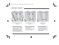
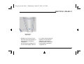
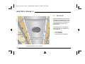


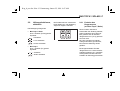
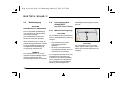

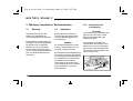

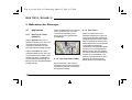

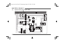
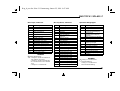

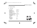

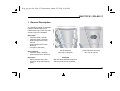


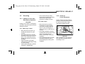
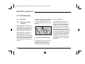
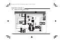
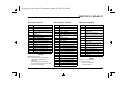


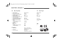

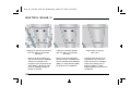
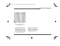


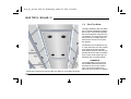

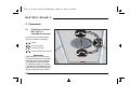
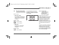


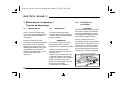
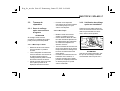
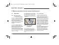

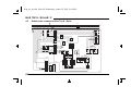

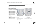
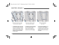

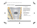

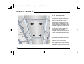

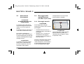

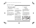
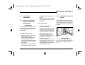
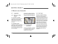

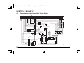

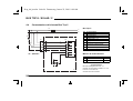


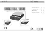
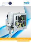


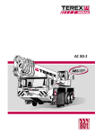


![[ Bedienungsanleitung ]](http://vs1.manualzilla.com/store/data/006735880_1-28334984de48ae2c5a8573c29f433271-150x150.png)