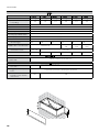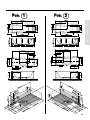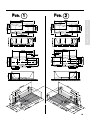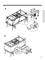
1
Pharo® Whirlpool
Pharo® FunPool
Funpool® 170x70
Funpool® 170x75
Funpool® 180x80
Funpool® 190x90
Funpool® 210x90
Funpool®140x140
23000xxx
23010xxx
23020xxx
23030xxx
23040xxx
23050xxx
Poolmaster Basic
Montageanleitung
Installation Instructions
Istruzioni di montaggio
Instructions de montage
Instrucciones de montaje
Montagehandleiding
Inhaltsverzeichnis
Contents
Indice
Deutsch
Vorwort
3
Sicherheitshinweise
5
In der Anleitung
7
verwendete Symbole
Technische Daten
8
170x70 / Maße / Technische Daten 12
170x75 / Maße / Technische Daten 14
180x80 / Maße / Technische Details16
190x90 / Maße / Technische Details18
140 x 140 / Maße /
Technische Daten
20
210 x 90/ Maße / Technische Daten 22
Ausstattung
24
Verpackungsinhalt
25
Benötigte Werkzeuge
27
Montagebeispiele
28
Whirlpoolmontage mit Schürze
30
Stromversorgung
34
Bedienelement Basic Poolmaster 36
Allgemeines / Pflegeanleitung Wanne
38
Störungen und Abhilfe
39
Service
42
Service Teile
44
Typenschilderklärung/
Konformitätserklärung
46
English
Preface
Safety Precautions
Symbols Used in the Instructions
Technical Data
170x70 / Dimensions /
Technical Data
170x75 / Dimensions /
Technical Data
180x80 / Dimensions /
Technical Data
190x90 / Dimensions /
Technical Data
140 x 140 / Dimensions /
Technical Data
210 x 90 / Dimensions /
Technical Data
Equipment
Packaging Contents
Required Tools
Installation example
Whirlpool installation with skirt
Power SUpply
Basic Poolmaster operation
Generally / Care instruction for tub
Trouble shooting
Service
Spare Parts
Explanation of nameplate /
declaration of conformity
Italiano
3
5
7
9
12
14
16
18
20
22
24
25
27
28
30
34
36
38
40
42
44
46
Introduzione
3
Prescrizioni di sicurezza
5
Simboli utilizzati nel manuale
7
dati Tecnici
10
170x70 / Dimensioni /dati tecnici 12
170x75 / Dimensioni /dati tecnici 14
180x80 / Dimensioni /dati tecnici 16
190x90 / Dimensioni /dati tecnici 18
140 x 140 / Dimensioni /dati tecnici20
210 x 90 / Dimensioni /dati tecnici 22
Equipaggiamento
24
Accessori coontenuti
25
Attrezzi necessari
27
Esempio di montaggio
28
Funzionalità del Basic Poolmaster 36
Generale/ precauzioni per
l’installazione della vasca
38
Risoluzione dei Problemi
41
Manutenzione
42
Parti Di Ricambio
44
Spiegazione targhetta/
dichiarazione di conformità
46
Vorwort
Preface
Introduzione
Information
Information
Informazione
Die Montageanleitung enthält die wichtigsten
Montageschritte und Installationshinweise.
Sie vermeiden Montagefehler wenn Sie die
Montageanleitung aufmerksam durchlesen.
Unsachgemäße Montage kann zu Verletzungen
führen!
Die
verwendeten Abbildungen
sind
Prinzipdarstellungen. Das Aussehen Ihres
Whirlpools kann von diesen Abbildungen
abweichen.
In der Montageanleitung wird der Einbau mit
der optional erhältlichen Wannenschürze für
Whirlpools der Serie Funpool beschrieben.
Dementsprechend entfallen Montageschritte
bei einem Whirlpool ohne Schürzen.
Die Montageanleitung an einem sicheren
Ort aufbewahren. Und an nachfolgende
Eigentümer/Nutzer weitergeben.
These installation instructions contain the
most important installing procedures and
installation notes.
Please read these instructions carefully in order
to avoid incorrect installation. Any improper
installation may lead to injuries!
The used illustrations are schematic
diagrams.
The following installation instructions will
describe the mounting of whirlpools with tub
skirt for whirlpools of 200 series. According to
this, mounting steps wouldn’t be done if these
tub skirt wouldn’t be installed.
Keep the installation / operating instructions
in a safe place and pass on to subsequent
owners/users.
Le istruzioni di montaggio descrivono le
più importanti operazioni di montaggio e
le avvertenze di installazione per i prodotti
indicati nella pagina di copertina. Leggere
attentamente le istruzioni di montaggio per
evitare errori.
Il montaggio scorretto può provocare lesioni!
Le illustrazioni d’uso sono schematizzate con
diagrammi.
Le seguenti istruzioni di montaggio
descriveranno il montaggio delle vasche con
i pannelli Funpool. Per questo motivo, le fasi
di montaggio descritte vanno tralasciate se la
vasca non va installata con i pannelli.
Riporre le istruzioni di montaggio e d‘uso in
un luogo sicuro. Consegnarle ai proprietari/
utenti futuri.
Normen und Richtlinien
Die Anwendung des Whirlpools ist durch
folgende Richtlinien gewährleistet:
Niederspannungsrichtlinie 2006/95/EWG
Richtlinie 89/336/EWG
EN61000-6-3
EN61000-3-3
DIN VDE 100 Teil 701: 2002
EN 60335-2-60-2003
EN 14516
EN 12764
EN 198
Stromversorgung:
Die gesamte Stromversorgung erfolgt
über:
- Wechselstromanschluss mit 230V/N/
PE/50Hz.
-Hauptschalter zur Netztrennung mit
3 mm Kontaktöffnung.
Die Stromversorgung muss eine
Fehlerstrom-Schutzeinrichtung
(RCD)
besitzen, der Bemessungsdifferenzstrom
ist von ≤ 30 mA abgesichert.
Elektro- Installation
Bei der Elektro-Installation sind die
entsprechenden VDE-, Landes- und
EVU-Vorschriften, in der jeweils gültigen
Fassung, einzuhalten.
Die Installations- und Prüfungsarbeiten
sind
von
einem
zugelassenen
Elektrofachmann
auszuführen.
Arbeiten am Whirlpool dürfen nur im
spannungsfreien Zustand vorgenommen
werden!
Wasserablauf und Wasserzulauf
Anschluss
für
Wasserablauf
und
Wasserzulauf sind nach den derzeitig
gültigen DIN 1988/EN1717
DIN1986/EN12056
und
den
örtlichen
Vorschriften
durchzuführen.
Standards and Directives
The use of the whirlpool is safeguarded
by the following Directives:
Low Voltage Directive 2006/95/EEC
Directive 89/336/EEC
EN61000-6-3
EN61000-3-3
DIN VDE 100 Teil 701: 2002
EN 60335-2-60-2003
EN 14516
EN 12764
EN 198
Power supply:
The complete power supply is performed
by means of:
-A.C. connection with 230V/N/PE/
50Hz.
-Circuit breaker for disconnection
from power supply with 3 mm
contact opening.
The power supply must have a residual
current device (RCD) which must provide
protection with a rated residual current
of ≤ 30 mA fuse.
Electrical installation
For electrical installation, all applicable
VDE,
country-specific
and
EVU
regulations
in
their
respectively
valid versions must be observed. All
installation and inspection works must
be carried out by an approved electrician
and in accordance with VDE 0100 Part
701. All works at the whirlpool may only
be carried out in a de-energized state!
Water inlet / Water drain
Connections for water inlet and drain
have to be installed according to the
currently valid DIN 1988/EN1717 /
DIN1986/EN12056 as well as local
regulations.
Norme e direttive
L’uso della vasca idromassaggio è
garantito dalle seguenti direttive:
direttiva sulla bassa tensione 2006/95/CEE
direttiva 89/336/CEE
EN61000-6-3
EN61000-3-3
DIN VDE 100 Teil 701: 2002
EN 60335-2-60-2003
EN 14516
EN 12764
EN 198
Alimentazione elettrica:
L’intero
sistema
elettrico
viene
alimentato:
- a tensione alternata a 230V/N/PE/
50Hz.
- con interruttore bipolare, con
apertura dei contatti di almeno 3
mm.
Il sistema elettrico deve possedere
un
Interruttore
magnetotermico
differenziale nominale ≤ 30 mA
Installazione elettrica
Per l'impianto elettrico si devono
rispettare le norme CEI e dell'azienda
elettrica vigenti.
I lavori di installazione e di collaudo
devono essere svolti da un tecnico
autorizzato. Qualsiasi intervento sulla
vasca va eseguito solo dopo aver
staccato la tensione elettrica!
Ingresso acqua/ scarico acqua
I collegamenti per acqua di mandata
e per l‘acqua di uscita devono essere
installati secondo le attuali norme DIN
1988/EN1717 / DIN1986/EN12056 ed
in conformità con le vigenti normative
locali.
Deutsch
Italiano
English
English
Italiano
Deutsch
Vorwort
Preface
Introduzione
Deutsch
English
Please assure before installation:
Vor dem Einbau bitte prüfen:
• Türbreite, im für die Installation • Observe door width in the room
vorgesehenen Raum, beachten.
where the whirlpool is to be
installed.
• EinbaudesProduktes,inVerbindungmit
optionalenSchürzen,infertiggefliestes • Installation
of
product,
in
combination with optional skirting,
Bad (Boden und Wände gefliest).
in a tiled bathroom (floor and walls
tiled).
Boden/ - ablauf
• Die Tragfähigkeit des Fußbodens
muss einer Belastung von 300 kg/m² Floor/ floor drain
• The floor's carrying capacity must
entsprechen.
correspond to a load of 300 kg/m².
• Der Fußboden muss ausreichend
The floor must be sufficiently leveled,
•
nivelliert sein, d.h. der Fußboden ist
i.e. it must be horizontal and even.
waagerecht und eben.
The whirlpool must be installed to
•
• Der Whirlpool muss auf einem,
a sealed floor for damp locations.
für
Feuchträume
geeigneten
Water can be splashed to the wall
Boden montiert werden. Durch die
and to the floor!
Whirlfunktion gelangtSpritzwasser aus
Water/ waste water
der Wanne!
• Please pay attention to the position of
Wasser/ Abwasser
the tub feet and installation area when
• Aufgrund des Wannenträgersystems
installing the water and waste supplies!
muss der Ablauf im Bodenbereich
The waste pipe must be positioned at
vorgesehen
werden.
Ein
floor level. Generally you cannot have
abwasserseitiger Anschluss aus der
the waste pipe coming out from the
Wand ist nicht möglich!
wall due to the Whirlpool Frame!
• NachDINEN12764musseinegeeignete
According to DIN EN 12764, a suitable
•
SicherungseinrichtunggegenRückfluss
safetydevicepreventingbackflowhasto
bauseits installiert werden. Dies
be installed by the customer.According
muss mindestens, nach EN 1717 eine
to EN 1717 this must at least consist of a
Sicherungskombination HD oder nach
HD safety combination or according to
DIN 1988 ein Rohrunterbrecher A1 in
DIN 1988 of a pipe interrupter A1 at the
derjeweilsrichtigenMontagehöhesein.
respectively correct installation height.
dem
anschließen
der
• Vor
•
Flushthewatersupplycircuitsaccording
Wasserzuleitungen müssen diese nach
to local regulations before installing.
DINfachgerechtdurchgespültwerden.
Electric powered
Elektro
• elektrischer Anschluss: Kabel 3 x 1,5 • electrical connection: cable 3 x 1.5 mm²
/ cable length 3500 mm
mm² / Kabellänge 3500 mm
• Potentialausgleich (Erdung): Kabel 4 • Earthing cable: cable 4 mm² / cable
length 3500 mm
mm² / Kabellänge 3500 mm
Italiano
Da controllare prima del montaggio:
• Fare attenzione all’apertura della
porta nel bagno dove verrà installata
la vasca.
• Il montaggio del prodotto, con
pannelli di protezione disponibili
come optional, deve essere fatto in
un bagno già piastrellato (pavimento
e parete).
Pavimento/ scarico a pavimento
• La portata minima del pavimento deve
essere di 300 kg/m².
• Il pavimento deve essere livellato e
sufficientemente piano.
• La vasca deve essere installata su
un pavimento resistente all’umidità.
L’acqua può essere spruzzata sul muro
and sul pavimento!
Acqua/ acqua di scarico
• Lo scarico deve essere posizionato al
livello del pavimento. Generalmente
non potete far uscire il tubo di scarico
dal muro a causa del telaio della vasca!
• Fareattenzioneallaposizionedeipiedini
della vasca e all‘area di installazione,
quandoinstallategliallacciamentiidrici
e lo scarico!
• Secondo la DIN EN 12764, in sede
di montaggio deve essere installato
un dispositivo di sicurezza idoneo
contro il riflusso. Secondo la EN 1717,
questo dispositivo deve essere una
combinazione di sicurezza HD o,
secondo la DIN 1988,un disconnettore
A1 all‘altezza di montaggio corretta.
• Il riempimento tramite il circuito
idraulico deve esse in conformità alle
vigenti normative locali.
Elettrico
• Connessione elettrica: cavo 3 x 1,5 mm2
/ lunghezza 3500 mm
• connessione terra: cavo 4 mm2 /
lunghezza 3500 mm
Sicherheitshinweise
Safety Precautions
Prescrizioni di sicurezza
Tip for using
• Elderly and handicapped persons
should exercise particular care when
using the whirlpool.
• The water temperature should not
exceed 40 °C.
• Do not exceed 20 minutes bathing time
with a water temperature of >= 38°C.
• Please contact your doctor if you have
health concerns.
• The pool must be emptied after each
bath.
Beispiele zur Nichtverwendung
• Die Whirlpools dürfen nicht im
öffentlichenBereicheingesetztwerden.
• Die Whirlpools dürfen nicht im
Außenbereich installiert werden.
• Kinderdürfennichtunbeaufsichtigtden
Whirlpool benutzen.
• z. B. Hunde, Katzen oder sonstige
Haustieredürfen nicht imWhirlpool der
Hygiene unterzogen werden.
Examples for non-using
• The whirlpools may not be used in
public areas.
• The whirlpools may not be used
outdoors.
• Children must not be left unattended in
the Whirlpool.
• e.g.dogs,cats or other animals must not
be wash in the whirlpool.
Esempi di uso
• Le persone anziane e disabili che hanno
difficoltà a muoversi devono prestare
particolare attenzione quando usano la
vasca idromassaggio.
• La temperatura dell’acqua non
dovrebbe superare i 40°C.
• La durata del bagno non deve superare
i 20 minuti con una temperatura
dell’acqua di >= 38°C.
• Consultate il vostro medico se avete
qualche malattia.
• La vasca deve essere svuotata dopo
ogni bagno.
Esempi di uso improprio
• Lavascaidromassaggiononpuòessere
usata in luoghi pubblici.
• Lavascaidromassaggiononpuòessere
usata all’aperto.
• I bambini non devono essere lasciati
incustoditi nella vasca.
• Per esempio i cani, i gatti o altri animali
non devono essere lavati nella vasca,
per questioni igeniche.
Deutsch
Hinweise zur Verwendung
• InihrerBewegungeingeschränkteältere
und behinderte Personen sollten bei
derNutzungdesWhirlpoolsbesondere
Sorgfalt walten lassen.
• Die Badewassertemperatur darf 40 °C
nicht übersteigen.
• KeineÜberschreitung der Badezeit von
20MinutenbeieinerWassertemperatur
von >= 38°C.
• Falls Sie gesundheitliche Bedenken
haben, setzen Sie sich mit Ihrem Arzt in
•
Verbindung.
• Nach jedem Bad muss der Pool entleert
werden.
Italiano
English
English
Italiano
Deutsch
Sicherheitshinweise
Safety Precautions
Prescrizioni di sicurezza
Deutsch
English
Während
Reinigungsund
Wartungsarbeiten muss der Haupt
schalter auf "OFF" gestellt sein.
- Wartungs- und Einstellarbeiten dürfen
nur von einem Fachmann durchgeführt
werden.
-Nach Wartungsarbeiten müssen
die Serviceabdeckungen ordnungs
gemäß montiert werden.
- Bestehende
Sicherheitsvorkehr
ungen und Sicherheitseinrichtungen
dürfen nicht verändert oder entfernt
werden.
- Der Whirlpool darf in seiner Bauart
nicht
verändert
werden.
Nur
Originalersatzteile verwenden.
-Elektrische Verbraucher > 12 V (Radio,
Föhn, usw.) dürfen nicht in der Nähe
oder im Whirlpool verwendet werden!
-The main switch must be set to "OFF"
during cleaning and maintenance
works.
- Maintenance and adjustment works
must be carried out by experts only.
-Allservicecoversmustbeappropriately
re-installed after maintenance works.
-Any installed safety provisions or safety
equipment may not be modified or
removed.
-The whirlpool’s construction must not
be changed.Only original components
may be used.
- Do not use higher voltage than 12 volts
(radio, hair-dryer, etc) in or close to the
whirlpool!
-
Italiano
-
Durante i lavori di pulizia e di
manutenzione, l'interruttore generale
deve essere su "OFF".
- Gli interventi di manutenzione e
regolazione devono essere svolti solo
da un tecnico autorizzato.
-Al termine della manutenzione si
devono rimontare correttamente le
coperture di servizio.
- I dispositivi di sicurezza installati non
devono essere né modificati né rimossi.
-La costruzione della vasca non deve
essere cambiata. Devono essere
utilizzati solo componenti originali.
-Non utilizzare apparecchi elettrici
>12V (radio,asciuga capelli...etc) nelle
vicinanze o all‘interno della vasca!
Non utilizzare silicone contenente acido
Do not use silicone containing acetic acid! acetico.
Kein essigsäurehaltiges Silikon
verwenden.
Durch Gebrauch von essigsäurehaltigem
Silikon können Acryl- bzw. Metallteile des
Whirlpools beschädigt werden.
Für dasVerfugen zwischen den Elementen
pilzhemmendesSanitärsilikonverwenden.
Dennoch kann es unter Umständen zu
Verfärbungen des Silikondichtstoffes
kommen.
Silikonfugen sind Wartungsfugen und
unterliegen nicht der Gewährleistung.
Acrylicormetalpartsof thewhirlpoolcanbe Utilizzando silicone contenente acido
damaged by the use of silicone containing acetico vi è il pericolo di danneggiare parti
acetic acid.
inmaterialeacrilicooppurepartimetalliche
della vasca.
For the flexible seals between the elements Per la sigillatura tra gli elementi
we advise to use schimmelwerende raccomandiamo l‘uso di silicone antimuffa
silicone kit. Despite this, and dependant per sanitari. Nonostante ciò, si possono
on circumstances, colorchanges in the kit verificaremacchieo colorimentidelsilicone
can happen. If cleaning does not bring sigillante. Nel caso in cui gli scolorimenti o
the wanted result, the seals have to be macchie non si lasciano eliminare pulendo
exchanged. Renewing is not within our semplicemente i giunti, è necessario
warranty.
sostituirli. I giunti di silicone sono giunti
soggetti a manutenzione e non fanno parte
della garanzia concessa.
Die Wanne vor Inbetriebnahme oder Test
The tub must be cleaned thoroughly with Prima della messa in esercizio oppure
der Whirlfunktionen gründlich mit der
the handshower befor using or testing the prima di eseguire la prova delle funzioni
Handbrause ausspülen!
whirlpool functions!
dell‘impiantowhirlpool,lavascadeveessere
sciacquatameticolosamenteconladoccetta
a mano!
Perform leak test.
Verificare possibili perdite d’acquta.
Dichtheitsprüfung und
InbetriebnahmeprüfunggemäßEN12764
durchführen
In der Anleitung Verwendete Symbole
Symbols Used in the Instructions
Simboli utilizzati nel manuale
ACHTUNG STROMSCHLAGGEFAHR
ATTENTION RISK OF ELECTRIC SHOCK
Nel presente manuale di istruzioni di montaggio si
trovanodeisimbolialcunideiqualisitrovanoapplicati
in alcuni punti del prodotto stesso. In questa parte
delladocumentazionesiprocedealladescrizionedel
significato di questi simboli.
ATTENZIONE PERICOLO DI SCOSSA
ELETTRICA
Segnalaalpersonaleinteressatochel'operazione
Meldet dem betreffenden Personal, dass der Informs the personnel concerned that the process
descritta può comportare il rischio di una scossa
beschriebeneVorgang,fallsnichtunterEinhaltung described, unless performed in compliance with
elettrica se non eseguita nel pieno rispetto delle
der Sicherheitsvorschriften ausgeführt,das Risiko the safety rules, bears the risk of electric shock.
norme di sicurezza.
eines elektrischen Schlags birgt.
ACHTUNG ALLGEMEINE GEFAHR
ATTENTION GENERAL HAZARD
ATTENZIONE PERICOLO GENERALE
Segnalaalpersonaleinteressatochel'operazione
Meldet dem betreffenden Personal, dass der Informs the personnel concerned that the process descritta può comportare il rischio di seri incidenti
beschriebeneVorgang,fallsnichtunterEinhaltung described, unless performed in compliance with se non eseguita nel pieno rispetto delle norme di
der Sicherheitsvorschriften ausgeführt,das Risiko the safety rules, bears the risk of injury.
sicurezza.
von Körperverletzungen birgt.
ACHTUNG ZWEI PERSONEN NOTWENDIG
ATTENTION: TWO PEOPLE REQUIRED!
BezeichneteinebestimmteVorgehensweise.Wenn
diese nicht eingehalten wird kann das Produkt
oder etwas in seiner Umgebung beschädigt
werden. (Die Montage muss von zwei Personen
durchgeführt werden)!
Describes a specific procedure. If this procedure
is not observed, the product or objects within
its environment may be damaged. (The steam
shower's installation must be carried out by two
people)!
HINWEIS
NOTE
Attenzione: sono necessarie due
persone!
Indicaundeterminatoprocedimento.Senonviene
rispettato,il prodotto o oggetti nelle sue vicinanze
possono essere danneggiati (il montaggio della
doccia a vapore deve essere eseguito da due
persone)!
NOTA BENE
Weist das betreffende Personal auf Informationen
Segnalaalpersonaleinteressatoinformazionicon
hin, deren Inhalt wichtig ist und berücksichtigt Informs the personnel concerned of information un contenuto importante che deve essere tenuto
werden soll.
with important contents to be observed.
in considerazione.
ELEKTRISCHER INSTALLATEUR
ELECTRICIAN
INSTALLATORE ELETTRICO
Fachtechniker,der imstande ist,das Produkt unter
normalen Bedingungen einzubauen. Er ist für
alle Eingriffe elektrischer Art wie Einstellungen,
Wartung und Reparaturen zuständig. Er ist
imstande,unterSpannunginSchaltschränkenoder
elektrischen Dosen zu arbeiten.
Specialist technician capable of installing the
productundernormalconditions.Heisresponsible
for all electrical work,such as setting,maintenance
and repairs.He is capable of working in energized
control cabinets or on electrical sockets.
Tecnico specializzato in grado di installare il prodotto
in normali condizioni di lavoro.Tra le sue competenze
rientrano tutti gli interventi di tipo elettrico come
registrazioni,manutenzioneeriparazioni.Eglièingrado
di intervenire in quadri elettrici ad armadio oppure su
prese per la corrente che si trovino sotto tensione.
Deutsch
In der vorliegenden Einbauanleitung und an The symbols described below appear in these
einigen Stellen auf dem Produkt selbst befinden Installation Instructions and in some locations on
sich Symbole, die hier unten beschrieben the product itself.
werden.
Italiano
English
English
Italiano
Deutsch
Technische Daten
Deutsch
170x70
Form
170x75
180x80
190x90
Rechteck
Rechteck
Sechseck
Eck
110
178
217
254
214
230
Material
ABS 20%, PMMA 80%
Abwasseranschluss
DN 50
elektr. Zuleitung
230V / 50Hz
Schutzart
IPX 5
Leistung Hydropumpe Basic
max.0,8 kW
Leistung Hydropumpe Combi
max.0,85 kW
Förderleistung
max. 380 L/min
10
10
Verpackungsgröße L x B x H
in mm
(B) Einstellbare Höhe der
Wanne min/max in mm
12
12
12
1970x1610
x980
1895x895x970
575 - 630
1600x1600
x1010
635 - 690
Option Exafill
Wasseranschluss kalt/warm
DN 20 3/4” Aussengewinde
Option Schürzen
(A) Schürzenhöhe in mm
545
Schürzenmontage
(C) Höhe der Wanne mit
Schürze inkl. 10mm Lüftungsabstand in mm
140x40
Rechteck
Inhalt + 1 Person (70kg) in L
Anzahl der Hydrodüsen
210x90
Rechteck
605
auf gefliesten Boden und vor gefliester Wand
605
660
10
1600x1600
x1010
Technical Data
English
170x75
180x80
190x90
oblong
oblong
hexagon
corner
110
178
217
254
214
230
Material
ABS 20%, PMMA 80%
Drain
DN 50
Electrical supply
Connected load hydropump
basic
max.0,8 kW
Connected load hydropump
combi
max.0,85 kW
Max.delivery rate
Italiano
IPX 5
English
230V / 50Hz
Degree of prot. against water
max. 380 L/min
10
10
Packaging dim. L x B x H in
mm
(B) Height of tub variable
min/max in mm
140x40
oblong
Tub capacity + 1 person
(70kg)
Number of water nozzles
210x90
oblong
Deutsch
170x70
Form
12
12
12
1970x1610
x980
1895x895x970
575 - 630
1600x1600
x1010
10
1600x1600
x1010
635 - 690
option Exafill
Water connection hot/cold
DN 20 3/4” external screw thread
option skirt
(A) Height of skirt in mm
545
Skirtmontage
(C) Height of tub with skirt
incl. 10mm aering-distance in mm
605
on tiled floor and against tiled wall
605
660
dati Tecnici
Italian
Forma
170x70
170x75
180x80
190x90
rettangolo
rettangolo
rettangolo
rettangolo
esagono
ad angolo
110
178
217
254
214
230
Capacità della vasca + 1 persona (70kg)
Materiale
DN 50
Alimentazione elettrica
230V / 50Hz
Grado di protezione
IPX 5
Potenza pompa idraulica Basic
max.0,8 kW
Potenza pompa idraulica Combi
max.0,85 kW
Portata
max. 380 L/min
10
10
Imballo dim. L x B x H in mm
(B) Altezza variabile della vasca min/max in mm
12
12
12
1970x1610
x980
1895x895x970
575 - 630
1600x1600
x1010
635 - 690
Opzione Exafill
Connessione acqua
fredda/calda
DN 20 3/4” filetto esterno della vite
Opzione pannelli di protezione
(A) Altezza del pannello esterno in mm
545
Montaggio pannelli di protezione
(C) Altezza della vasca con
pannello incluso 10 mm
di areazione.
10
140x40
ABS 20%, PMMA 80%
Scarico
Numero bocchette
idromassaggio
210x90
605
su pavimento piastrellato e davanti parete piastrellata
605
660
10
1600x1600
x1010
11
Italiano
English
Deutsch
170x70 / Masse / Technische Daten
170x70 / Dimensions / Technical Data
170x70 / Dimensioni /dati tecnici
Deutsch
Legende:
Die Abb. ist ein Montagebeispiel, es
sind noch weitere Einbausituationen
möglich.
A 1,2... mögliche Serviceöffnungen für
Technik (Abmessung 500x500 mm)
XEmpfohlener Bereich für den Kalt(rechts) und den Warmwasseranschluss
(links) DN 15.
YEmpfohlener Bereich für den
Wasserablauf DN 50 (Boden: Oberkante
Anschlussmuffe bündig Standfläche
Wannenfüße)
ZAnschluss der elektrischen Zuleitung
und des Potentialausgleichs (Erdung)*
im gesamten Bereich der Wand
möglich. Ausreichend Abstand zu den
Außenkanten einhalten!
Wannenfuß
Poolmaster Basic
Haltegriff
Pos. Einbauposition mit Serviceöffnung und
Pumpe links
Pos. Einbauposition mit Serviceöffnung und
Pumpe rechts
*
12
Querschnitt von mindestens 4 mm2
English
Legend:
The picture is an installation example,
it‘s possible to install other situations.
A 1,2... possible service opening area for
maintenance (dimensions 500x500 mm)
XRecommended position for cold
water connection (right) and hot water
connection (left) DN 15.
YRecommended position for the water
drainage Ø 50 (floor: upper rim of
connection pipe flush with tub feet
contact area).
ZThe electrical supply and the earth cable
connection* are made out of the wall.
Keep an adequate distance to the outer
edges of the tub!
tub feet
Poolmaster Basic
grab bar
Pos. Installation position with service
opening area and pump left
Pos. Installation position with service
opening area and pump right
*Cross-section at least 4 mm2
Italiano
Legenda:
Il disegno è un esempio di installazione,
è possibile installare la vasca in altre
configurazioni.
A 1,2,3... possibili aree di ispezione tecnica
(dimensioni 500x500 mm)
X Posizione raccomandata per
connessione acqua fredda (destra)
e connessione acqua calda (sinistra)
DN15.
Y Posizione raccomandata per lo scarico
d’acqua Ø 50 (Pavimento: il bordo più
alto della connessione a livello dei
piedini della vasca)
ZLa fornitura elettrica e cavo di
connessione terra(*) sono fatte fuori dal
muro. Tenere una adeguata distanza dai
bordi della vasca!
piedini vasca
Poolmaster Basic
Maniglia
Pos.
area di ispezione e pompa con
posizione sinistra
Pos.
area di ispezione e pompa con
posizione destra
2
* sezione minima 4 mm
Italiano
English
Deutsch
Pos. 1
Y
Pos. 2
Z
Z
X
X
Y
13
170x75 / Masse / Technische Daten
170x75 / Dimensions / Technical Data
170x75 / Dimensioni /dati tecnici
Deutsch
Legende:
Die Abb. ist ein Montagebeispiel, es
sind noch weitere Einbausituationen
möglich.
A 1,2... mögliche Serviceöffnungen für
Technik (Abmessung 500x500 mm)
XEmpfohlener Bereich für den Kalt(rechts) und den Warmwasseranschluss
(links) DN 15.
YEmpfohlener Bereich für den
Wasserablauf DN 50 (Boden: Oberkante
Anschlussmuffe bündig Standfläche
Wannenfüße)
ZAnschluss der elektrischen Zuleitung
und des Potentialausgleichs (Erdung)*
im gesamten Bereich der Wand
möglich. Ausreichend Abstand zu den
Außenkanten einhalten!
Wannenfuß
Poolmaster Basic
Haltegriff
Pos. Einbauposition mit Serviceöffnung und
Pumpe links
Pos. Einbauposition mit Serviceöffnung und
Pumpe rechts
*
14
Querschnitt von mindestens 4 mm2
English
Legend:
The picture is an installation example,
it‘s possible to install other situations.
A 1,2... possible service opening area for
maintenance (dimensions 500x500 mm)
XRecommended position for cold
water connection (right) and hot water
connection (left) DN 15.
YRecommended position for the water
drainage Ø 50 (floor: upper rim of
connection pipe flush with tub feet
contact area).
ZThe electrical supply and the earth cable
connection* are made out of the wall.
Keep an adequate distance to the outer
edges of the tub!
tub feet
Poolmaster Basic
grab bar
Pos. Installation position with service
opening area and pump left
Pos. Installation position with service
opening area and pump right
*Cross-section at least 4 mm2
Italiano
Legenda:
Il disegno è un esempio di installazione,
è possibile installare la vasca in altre
configurazioni.
A 1,2,3... possibili aree di ispezione tecnica
(dimensioni 500x500 mm)
X Posizione raccomandata per
connessione acqua fredda (destra)
e connessione acqua calda (sinistra)
DN15.
Y Posizione raccomandata per lo scarico
d’acqua Ø 50 (Pavimento: il bordo più
alto della connessione a livello dei
piedini della vasca)
ZLa fornitura elettrica e cavo di
connessione terra(*) sono fatte fuori dal
muro. Tenere una adeguata distanza dai
bordi della vasca!
piedini vasca
Poolmaster Basic
Maniglia
Pos.
area di ispezione e pompa con
posizione sinistra
Pos.
area di ispezione e pompa con
posizione destra
* sezione minima 4 mm2
Italiano
English
Deutsch
Pos. 1
X
Pos. 2
Z
Z
Y
X
Y
15
180x80 / Masse / Technische Details
180x80 / Dimensions / Technical Data
180x80 / Dimensioni /dati tecnici
Deutsch
Legende:
Die Abb. ist ein Montagebeispiel, es
sind noch weitere Einbausituationen
möglich.
A 1,2... mögliche Serviceöffnungen für
Technik (Abmessung 500x500 mm)
XEmpfohlener Bereich für den Kalt(rechts) und den Warmwasseranschluss
(links) DN 15.
YEmpfohlener Bereich für den
Wasserablauf DN 50 (Boden: Oberkante
Anschlussmuffe bündig Standfläche
Wannenfüße)
ZAnschluss der elektrischen Zuleitung
und des Potentialausgleichs (Erdung)*
im gesamten Bereich der Wand
möglich. Ausreichend Abstand zu den
Außenkanten einhalten!
Wannenfuß
Poolmaster Basic
Haltegriff
Pos. Einbauposition mit Serviceöffnung und
Pumpe links
Pos. Einbauposition mit Serviceöffnung und
Pumpe rechts
*
16
Querschnitt von mindestens 4 mm2
English
Legend:
The picture is an installation example,
it‘s possible to install other situations.
A 1,2... possible service opening area for
maintenance (dimensions 500x500 mm)
XRecommended position for cold
water connection (right) and hot water
connection (left) DN 15.
YRecommended position for the water
drainage Ø 50 (floor: upper rim of
connection pipe flush with tub feet
contact area).
ZThe electrical supply and the earth cable
connection* are made out of the wall.
Keep an adequate distance to the outer
edges of the tub!
tub feet
Poolmaster Basic
grab bar
Pos. Installation position with service
opening area and pump left
Pos. Installation position with service
opening area and pump right
*Cross-section at least 4 mm2
Italiano
Legenda:
Il disegno è un esempio di installazione,
è possibile installare la vasca in altre
configurazioni.
A 1,2,3... possibili aree di ispezione tecnica
(dimensioni 500x500 mm)
X Posizione raccomandata per
connessione acqua fredda (destra)
e connessione acqua calda (sinistra)
DN15.
Y Posizione raccomandata per lo scarico
d’acqua Ø 50 (Pavimento: il bordo più
alto della connessione a livello dei
piedini della vasca)
ZLa fornitura elettrica e cavo di
connessione terra(*) sono fatte fuori dal
muro. Tenere una adeguata distanza dai
bordi della vasca!
piedini vasca
Poolmaster Basic
Maniglia
Pos.
area di ispezione e pompa con
posizione sinistra
Pos.
area di ispezione e pompa con
posizione destra
2
* sezione minima 4 mm
Italiano
English
Deutsch
Pos. 1
X
Pos. 2
Z
Z
Y
X
Y
17
190x90 / Masse / Technische Details
190x90 / Dimensions / Technical Data
190x90 / Dimensioni /dati tecnici
Deutsch
Legende:
Die Abb. ist ein Montagebeispiel, es
sind noch weitere Einbausituationen
möglich.
A 1,2... mögliche Serviceöffnungen für
Technik (Abmessung 500x500 mm)
XEmpfohlener Bereich für den Kalt(rechts) und den Warmwasseranschluss
(links) DN 15.
YEmpfohlener Bereich für den
Wasserablauf DN 50 (Boden: Oberkante
Anschlussmuffe bündig Standfläche
Wannenfüße)
ZAnschluss der elektrischen Zuleitung
und des Potentialausgleichs (Erdung)*
im gesamten Bereich der Wand
möglich. Ausreichend Abstand zu den
Außenkanten einhalten!
Wannenfuß
Poolmaster Basic
Haltegriff
Pos. Einbauposition mit Serviceöffnung und
Pumpe links
Pos. Einbauposition mit Serviceöffnung und
Pumpe rechts
*
18
Querschnitt von mindestens 4 mm2
English
Legend:
The picture is an installation example,
it‘s possible to install other situations.
A 1,2... possible service opening area for
maintenance (dimensions 500x500 mm)
XRecommended position for cold
water connection (right) and hot water
connection (left) DN 15.
YRecommended position for the water
drainage Ø 50 (floor: upper rim of
connection pipe flush with tub feet
contact area).
ZThe electrical supply and the earth cable
connection* are made out of the wall.
Keep an adequate distance to the outer
edges of the tub!
tub feet
Poolmaster Basic
grab bar
Pos. Installation position with service
opening area and pump left
Pos. Installation position with service
opening area and pump right
*Cross-section at least 4 mm2
Italiano
Legenda:
Il disegno è un esempio di installazione,
è possibile installare la vasca in altre
configurazioni.
A 1,2,3... possibili aree di ispezione tecnica
(dimensioni 500x500 mm)
X Posizione raccomandata per
connessione acqua fredda (destra)
e connessione acqua calda (sinistra)
DN15.
Y Posizione raccomandata per lo scarico
d’acqua Ø 50 (Pavimento: il bordo più
alto della connessione a livello dei
piedini della vasca)
ZLa fornitura elettrica e cavo di
connessione terra(*) sono fatte fuori dal
muro. Tenere una adeguata distanza dai
bordi della vasca!
piedini vasca
Poolmaster Basic
Maniglia
Pos.
area di ispezione e pompa con
posizione sinistra
Pos.
area di ispezione e pompa con
posizione destra
2
* sezione minima 4 mm
Italiano
English
Deutsch
Pos. 1
X
Pos. 2
Z
Z
Y
X
Y
19
140 x 140 / Masse / Technische Daten
140 x 140 / Dimensions / Technical Data
140 x 140 / Dimensioni /dati tecnici
Deutsch
Legende:
Die Abb. ist ein Montagebeispiel, es
sind noch weitere Einbausituationen
möglich.
A 1,2... mögliche Serviceöffnungen für
Technik (Abmessung 500x500 mm)
XEmpfohlener Bereich für den Kalt(rechts) und den Warmwasseranschluss
(links) DN 15.
YEmpfohlener Bereich für den
Wasserablauf DN 50 (Boden: Oberkante
Anschlussmuffe bündig Standfläche
Wannenfüße)
ZAnschluss der elektrischen Zuleitung
und des Potentialausgleichs (Erdung)*
im gesamten Bereich der Wand
möglich. Ausreichend Abstand zu den
Außenkanten einhalten!
Wannenfuß
Poolmaster Basic
Haltegriff
Pos. Einbauposition mit Serviceöffnung und
Pumpe links
Pos. Einbauposition mit Serviceöffnung und
Pumpe rechts
*
20
Querschnitt von mindestens 4 mm2
English
Legend:
The picture is an installation example,
it‘s possible to install other situations.
A 1,2... possible service opening area for
maintenance (dimensions 500x500 mm)
XRecommended position for cold
water connection (right) and hot water
connection (left) DN 15.
YRecommended position for the water
drainage Ø 50 (floor: upper rim of
connection pipe flush with tub feet
contact area).
ZThe electrical supply and the earth cable
connection* are made out of the wall.
Keep an adequate distance to the outer
edges of the tub!
tub feet
Poolmaster Basic
grab bar
Pos. Installation position with service
opening area and pump left
Pos. Installation position with service
opening area and pump right
*Cross-section at least 4 mm2
Italiano
Legenda:
Il disegno è un esempio di installazione,
è possibile installare la vasca in altre
configurazioni.
A 1,2,3... possibili aree di ispezione tecnica
(dimensioni 500x500 mm)
X Posizione raccomandata per
connessione acqua fredda (destra)
e connessione acqua calda (sinistra)
DN15.
Y Posizione raccomandata per lo scarico
d’acqua Ø 50 (Pavimento: il bordo più
alto della connessione a livello dei
piedini della vasca)
ZLa fornitura elettrica e cavo di
connessione terra(*) sono fatte fuori dal
muro. Tenere una adeguata distanza dai
bordi della vasca!
piedini vasca
Poolmaster Basic
Maniglia
Pos.
area di ispezione e pompa con
posizione sinistra
Pos.
area di ispezione e pompa con
posizione destra
2
* sezione minima 4 mm
Italiano
English
Deutsch
Pos. 1
Pos. 2
Z
X
Z
Y
Y
X
21
210 x 90/ Masse / Technische Daten
210 x 90 / Dimensions / Technical Data
210 x 90 / Dimensioni /dati tecnici
Deutsch
Legende:
Die Abb. ist ein Montagebeispiel, es
sind noch weitere Einbausituationen
möglich.
A 1,2... mögliche Serviceöffnungen für
Technik (Abmessung 500x500 mm)
XEmpfohlener Bereich für den Kalt(rechts) und den Warmwasseranschluss
(links) DN 15.
YEmpfohlener Bereich für den
Wasserablauf DN 50 (Boden: Oberkante
Anschlussmuffe bündig Standfläche
Wannenfüße)
ZAnschluss der elektrischen Zuleitung
und des Potentialausgleichs (Erdung)*
im gesamten Bereich der Wand
möglich. Ausreichend Abstand zu den
Außenkanten einhalten!
Wannenfuß
Poolmaster Basic
Haltegriff
Pos. Einbauposition mit Serviceöffnung und
Pumpe links
Pos. Einbauposition mit Serviceöffnung und
Pumpe rechts
*
22
Querschnitt von mindestens 4 mm2
English
Legend:
The picture is an installation example,
it‘s possible to install other situations.
A 1,2... possible service opening area for
maintenance (dimensions 500x500 mm)
XRecommended position for cold
water connection (right) and hot water
connection (left) DN 15.
YRecommended position for the water
drainage Ø 50 (floor: upper rim of
connection pipe flush with tub feet
contact area).
ZThe electrical supply and the earth cable
connection* are made out of the wall.
Keep an adequate distance to the outer
edges of the tub!
tub feet
Poolmaster Basic
grab bar
Pos. Installation position with service
opening area and pump left
Pos. Installation position with service
opening area and pump right
*Cross-section at least 4 mm2
Italiano
Legenda:
Il disegno è un esempio di installazione,
è possibile installare la vasca in altre
configurazioni.
A 1,2,3... possibili aree di ispezione tecnica
(dimensioni 500x500 mm)
X Posizione raccomandata per
connessione acqua fredda (destra)
e connessione acqua calda (sinistra)
DN15.
Y Posizione raccomandata per lo scarico
d’acqua Ø 50 (Pavimento: il bordo più
alto della connessione a livello dei
piedini della vasca)
ZLa fornitura elettrica e cavo di
connessione terra(*) sono fatte fuori dal
muro. Tenere una adeguata distanza dai
bordi della vasca!
piedini vasca
Poolmaster Basic
Maniglia
Pos.
area di ispezione e pompa con
posizione sinistra
Pos.
area di ispezione e pompa con
posizione destra
2
* sezione minima 4 mm
Italiano
English
Deutsch
Pos. 1
X
Y
Pos. 2
Z
Z
X
Y
23
Ausstattung
Equipment
Equipaggiamento
Deutsch
English
Wassersystem:
• Wasserdüsen
• Poolmaster Basic
• Flexaplus Ab-/Überlaufkombination
Option:
• Schürze lang
• Schürze kurz
• Exafill
• Haltegriff
• Nackenkissen
Watersystem:
• hydro nozzle
• Poolmaster Basic
• Flexaplus water-/overflow combination
Option:
• skirt front
• skirt side
• exafill
• hand grip
• neck
24
Italiano
Sistema acqua:
• Bocchette idromassaggio
• Poolmaster Basic
• Flexaplus scarico/ troppopieno
Opzioni:
• Pannello frontale
• Pannello laterale
• Exafill
• Maniglia
• Poggiatesta
Verpackungsinhalt
Packaging Contents
Accessori coontenuti
Deutsch
a
Italiano
Contenuti nell’imballo:
a 1x vasca assemblata
b 2x molla fissaggio a muro
c 12xTassello (6x30)
Option:
Opzionale:
d Skirt
d Pannelli
e Screws M6 x 35mm
e Vite M6x35
fNut M6
f
Dado M6
gRounded head screw (4x34mm) gVite TCB 4x34
h 12xCounter sunk screw (4 x 39mm) h 12xVite TSP 4x39
i Washer
i Rondella
kCap
kCappuccio
lSpacer
lStaffa millefori
m
Brackets
m
Molla per pannello
n
Fastening brackets
nStaffa tubo quadro
o
neck pillow
o
Poggiatesta
b
English
Deutsch
Packing Contents:
a 1xTub with attachment parts
b 2x Wall brackets
c 12x Dowel (Ø 6 x 30 mm)
Italiano
Verpackungsinhalt:
a 1x Wanne mit Anbauteilen
b 2x Wandhalter
c 12x Dübel (Ø 6x 30 mm)
Option:
d Schürze
e Schrauben M6 x 35mm
fSchraubenmuttern M6
gLinsenkopfschrauben (4x34mm)
h 12xSenkkopfschrauben (4x39mm)
i Unterlegscheiben
kAbdeckkappen
lAbstandhalter
m
Kunststoffklammern
n
Befestigungsbügel
oNackenkissen
English
c
e g h i k
f
d
m
l
n
o
25
26
Italiano
Folgend aufgeführtes Werkzeug und Zubehör ist für die Montage notwendig:
- Wasserwaage
- Meterstab
- Zeichenstift und Körner
- Wasserpumpenzange
- Maulschlüssel-Set (SW 10, 15)
- Kreuzschlitzschraubendreher
- Hammer (kleiner Schlosserhammer)
- Armaturenfett
- Silikon (essigsäurefrei)
- Bohrer (Ø6 mm)
- Messer
- Bohrmaschine
- 2 Montageböcke
The following tools and accessories are required for installation:
- Spirit level
- Pocket rule
- Pencil and punch
- Water pump pliers
- Wrench set (SW 10,15)
- Crosstip screwdriver
- Hammer (small fitter's hammer)
- Fittings grease
- Silicone (free of acetic acid)
- Drill (Ø6 mm)
- Knife
- Drilling machine
- 2 installation blocks
Per il montaggio sono necessari i seguenti
attrezzi ed accessori:
- Livella a bolla d'aria
- Metro
- Matita e punzone (per piastrelle)
- Chiave stringitubo
- Set di chiavi fisse (da 10,15)
- Cacciavite a stella
- Martello (non da fabbro)
- Grasso per rubinetteria
- Silicone (privo di acido acetico)
- Punta (Ø6 mm)
- Coltello
- Trapano
- 2 cavalletti di montaggio
English
English
Italiano
Deutsch
Deutsch
Benötigte Werkzeuge
Required Tools
Attrezzi necessari
27
Montagebeispiele
Installation example
Esempio di montaggio
Deutsch
A
English
A
Montagebeispiele ohne Wannenrandthermostat
Whirlpool mit mindestens einer längs Seite
oder mehreren Seiten zur Wand montiert.
Mit Wannenschürze(n) der Whirlpool Serie
Funpool verkleidet.
Lüftung und Service durch abnehmbare
Schürze(n) gewährleistet. (Die Montage mit
Schürze wird ab Seite 34 beschrieben).
Installation examples, without tub rim thermostat
Whirlpool installed with at least one long side
or several sides to the wall and covered with
tub skirt(s) of the Whirlpool series Funpool.
Ventilation
and
service
ensured
by
removable
skirt(s).
(The installation of Whirlpool with skirt is
described in the following).
B
B
Montagebeispiel ohne Wannenrandthermostat
Whirlpool mit mindestens einer längs Seite
oder mehreren Seiten zur Wand montiert.
Lüftungöffnung min. 150 cm2 (3)und
Serviceöffnung min. 300 cm2 (2).
Diese Öffnung kann wahlweise:
- an Längsseite der Wannenverkleidung
- an Querseite der Wannenverkleidung
- oder im Nebenraum
angebracht sein.
C
Montagebeispiel Whirlpool aufgelegt
Lüftung durch Lüftungsluke(3) gewährleistet.
Service durch herausheben des kompletten
Whirlpools möglich.
Es ist zu beachten, daß:
- die Anschlussleitungen (Strom, Wasser,
Abwasser) von der Lüftungsluke (3)
montiert und demontiert werden
können.
- die Befestigungspunkte von der
Lüftungsluke (3) gelöst werden können.
- bei einer Dachschräge der Whirlpool
für Servicezwecke komplett nach oben
aus der Ummauerung gehoben werden
kann.
- die Wanne am Rand (4) mit
essigsäurefreiem Silikon abgedichtet ist.
Wird die Wanne fest ummauert gilt:
- im Bereich der Verkleidung muß eine
Sicherheitsöffnung vorhanden sein.
- Die Position der Sicherheitsöffnung
liegt 20 mm unter den elektrischen
Aggregaten (Abb D)!
So kann bei einer Lekage das Wasser sichtbar
abfließen.
28
Installation examples, without tub rim thermostat
Whirlpool installed with at least one
longitudinal side or several sides against the
wall.
Air opening: 150 cm2 (3) minimum and
service opening: 300 cm2 (2) minimum.
This opening can be located optionally:
- on the longitudinal side of the tub panelling
- on the transverse side of the tub panelling
- or in a neighbouring room.
C
Installation example
Laid on whirlpool installation
Ventilation ensured by ventilation hatch (3).
Service possible by lifting out the complete
whirlpool.
- Make sure during the installation that
the connections (electricity, water, drain)
can be connected and disconnected
through the ventilation hatch (3)!
- It must be possible to disconnect
the attachment points through the
ventilation hatch (3).
- It must be possible to lift out the
complete whirlpool upward out of
the embedding for service purposes!
Caution when installing the whirlpool
under a pitched roof!
- The tub must be sealed at the edge (4)
with silicone (free from acetic acid).
If the tub is walled in or otherwise enclosed,
a safety hatch must be present in the lower
area of the enclosure according to the TÜV
regulations so that, when a leak occurs under
the tub, the water can be seen to flow away.
The bottom edge of the safety opening must
be 20 mm below the electrical assemblies of
the whirlpool tub (Fig. D)!
Italiano
A
Esempi di montaggio senza termostato
bordo vasca
Vasche installate con uno o più lati a muro
e con pannelli/o per vasche serie Funpool.
La ventilazione e il servizio è assicurato dai
pannelli ispezionabili. (l’installazione delle
vasche con i pannelli è descritta in seguito).
B
Esempi di montaggio senza termostato
bordo vasca
Whirlpool con almeno un lato lungo o più lati
montati al muro.
Apertura di ventilazione min. 150 cm² (3) ed
apertura d’ispezione min. 300 cm² (2).
Questa apertura può essere montata a
scelta:
- sul lato lungo del rivestimento della vasca
- sul traverso del rivestimento della vasca
- o nella stanza attigua.
C
Esempio di installazione
Installazione vasca in centro stanza.
La ventilazione è assicurata dalla grata (3).
Il servizio è possibile solo sollevando
completamente la vasca.
- Essere sicuri che durante l’installazione
le connessioni(elettrica, idrica e scarico)
possono essere effettuate attraverso la
grata di ventilazione (3)!
- Deve essere possibile disconnettere i
punti di attacco attraverso la grata di
ventilazione.
- Deve essere possibile sollevare
completamente la vasca fuori dalla
muratura per il servizio tecnico!
- La vasca deve essere siliconata ai bordi
(4) con silicone non acetico.
Se la vasca è circondata da mura bisogna
osservare quanto segue:
- La presenza di un’apertura di sicurezza
nell’area della muratura è obbligatoria.
- La posizione dell’apertura di sicurezza
è 20 mm sotto il gruppo elettrico della
vasca (fig. D)!
Così in caso di una perdita l’acqua può
scorrere fuori dalla vasca.
Italiano
English
Deutsch
A
B
3
2
C
D
4
3
29
Whirlpoolmontage mit Schürze
Whirlpool installation with skirt
Montaggio vasca con pannello
Deutsch
English
Italiano
Whirlpoolmontage mit Schürze:
Installation of whirlpool with skirt:
Montaggio vasca con pannello:
Die Montage des Whirlpools muss von zwei
Personen durchgeführt werden!
Two persons are required to install the
whirlpool!
Sono richieste due persone per installare la
vasca!
Whirlpool ausschließlich am Gestell oder am
Wannenrand anheben.
Always lift the whirlpool by the frame or the
tub rim.
Sollevare sempre la vasca dal telaio o dai
bordi vasca.
Vorbereitungen zur Installation
Preparations for installation
Preparazione per l’installazione
Abb. A:
a) Whirlpool an den Einbauort bringen
und vorsichtig Verpackung entfernen.
b) Den Whirlpool umdrehen und auf
geschützte Montageböcke lagern.
c) Die Kunststoffklammern (1) in
die Halteschienen (2) unter dem
Wannenrand einschieben.
Fig. A:
a) Transport the whirlpool to the
installation position and carefully
remove the packaging.
b) Turn the whirlpool over and place it on
protected assembly stands.
c) Slide the plastic clamps (1) into the
support rails (2) underneath the tub rim.
Die Abstandsbügel müssen symmetrisch
ausgerichtet werden!
Schutzfolie an Wannenschürze nicht
entfernen!
The spacers have to be aligned
symmetrically!
Do not remove the protective foil from the
tub skirt!
d) Die Abstandshalter (3) und
Befestigungsbügel (4) mit Schrauben
M6 x 40 (5) und Muttern M6 (6) am
Rahmen (7) befestigen und leicht
anziehen.
e) Die Wannenschürzen anbringen und
mit Wasserwaage und durch verstellen
der Abstandsbügel vertikal ausrichten.
Anschließend Muttern M6 (6) fest
anziehen.
d) Attach spacers (3) and attachment
brackets (4) to the frame (7) and lightly
tighten with screws M6 x 40 (5) and nuts
M6 (6).
e) Install the tub skirt(s) and align them
vertically by means of a spirit level by
adjusting the spacers. Then fully tighten
the nut M6 (6).
Abb. B:
f) Schürze mit Unterlegscheibe (8) und
Linsenkopfschraube 4 x 34mm (9) mit
den Abstandhaltern verschrauben.
g) Die Kontermuttern (SW 15) an den
Wannenfüßen lösen und diese mit
Wasserwaage ausnivelieren, so dass
zwischen Standfläche Wannenfüße und
Unterkante Schürze ein Abstand von 10
mm entsteht.
h) Schürzen entfernen und Whirlpool von
den Böcken nehmen.
30
Fig. B:
f) Screw the skirt with the washer (8) and
the cross head screw 4 x 34 mm (9) to
the spacers.
g) Loosen the locking nuts (15 mm
spanner) from the tub feet and level
them with the spirit level so that there
is a 10 mm space between the tub feet
contact area and the lower rim of the
skirt.
h) Remove the skirt(s) and take the
whirlpool from the stands.
Fig. A:
a) Portare la vasca vicino nella posizione di
installazione e facendo attenzione nel
rimuovere l’imballo.
b) Girare la vasca sottosopra e piazzarla
sui cavalletti.
c) Inserire la molla per pannello (1)
all’interno del supporto (2) posti sotto il
bordo vasca.
Le staffe millefori devono essere allineate
simmetricamente!
Non rimuovere il film protettivo dal
pannello!
d) Montare le staffe millefori (3) e la staffa
tubo quadro (4) al telaio (7) fissandole
leggermente con le viti M6x40 (5) e il
dado M6 (6).
e) Installare il pannello/i e allinearlo
verticalmente facendo uso di una bolla
aggiustando la posizione della staffa
millefori. Poi chiudere il dado M6 (6).
Fig. B:
f) Sul pannello fare un foro da 4 mm in
corrispondenza di ogni staffa millefori e
avvitare con il sottocappuccio (8) la vite
TCB 3,9x34 (9) alla staffa.
g) Con la chiave da 15 allentare i dadi dai
piedini della vasca e regolarli utilizzando
una livella in modo che ci siano 10 mm
di spazio tra i piedini e il punto più
basso del pannello.
h)Rimuovere i pannelli e prendere la vasca
dalle gambe.
ca.10 mm
2
Italiano
3
English
4
7
Deutsch
A
6
5
1
B
9
8
31
Whirlpoolmontage mit Schürze
Whirlpool installation with skirt
Montaggio vasca con pannello
Deutsch
English
Italiano
Abb. A: Wandmontage Wanne
1 Wand
2 Fliesen
4 Wanne
5Schallschutzband
6 Wannenanker
7 Unterkonstruktion
Fig. A: Wall installation of tub
1 wall
2 tiles
4 tub
5 sound insulation tape
6 wall anchor
7 substructure
Fig. A: Montaggio a parete della vasca
1 parete
2 piastrelle
4 vasca
5 nastro insonorizzante
6 ancoraggio vasca
7 sottostruttura
Abb. B:
a) An den Wannenrand, mit Kontakt
zur Wand, das Schallschutzband (5)
anbringen.
Fig. B:
a) Attach sound insulation tape (5) to the
tub edge with contact to the wall.
Fig. B:
a) Attaccare il nastro isolante al bordo
superiore (5) della vasca a contatto con
il muro.
Abb. C:
a) Wanne an endgültiger Position
positionieren und Nivellierung
überprüfen. Gegebenenfalls müssen
die Füße nachjustiert werden.
Kontermuttern (SW 15) an den
Wannenfüßen anziehen.
b) Unterer Wannenrand an der Wand
anzeichnen und Wanne von der Wand
entfernen.
Abb. D: Wannenankermontage
a) Die Wannenanker mit Klemmbügel (1
und 2) werden an den Außenenden der
Wanne montiert.
Dabei sollte der Abstand von der
Außenkante des Wannenkörpers ca
50 - 70 mm betragen, bzw. so gewählt
werden, dass der Klemmbügel nach
Auflegen der Wanne bequem arretiert
werden kann.
Der Wannenanker ohne Klemmbügel (3)
wird in der Ecke montiert.
b) Die Wanne nach Montage der
Wannenanker auflegen und die
Nivellierung nochmals überprüfen.
c) Flügelmutter am Wannenanker lösen,
Spannbügel nach oben drücken und
Flügelmutter festdrehen (siehe Abb. A /
Wannenmontage)
ohne Abbildung
Wasserablauf anschließen
Abwasseranschluss DN 50
vormontieren, Wanenablauf
anschließen.
32
Fig. C:
a) Place whirlpool in it‘s final position and
check the alignement with the spirit
level. As necessary re-adjust the tub
feets. Tighten the locking nuts (SW 15)
at the tub feets.
b) Draw lower bath tub edge and replace
it.
Fig. D: wall anchor installation
a) The wall anchors with clamping yoke (1
and 2) are mounted at the outer ends of
the tub.
The distance to the outer ends of the
tub should be 50 -70 mm or should be
voted so that the clamping yokes can be
adjusted comfortably after establishing
the tub.
The wall anchors without clamping yoke
(3) is mounted at the edge.
b) After mounting of the wall anchors
establishing the tub and check the
alignement again.
c) Unsrew wing nut at the wall anchor,
presseing up clamping yoke and tighten
wing nut (see Fig. A / tub installation).
without figure
connection of water drainage
Connect drain to the prepared drain
connection DN 50.
Fig. C:
a) Posizionare la vasca nella posizione
finale e controllare con la livella. Se
necessario riaggiustare l’altezza dei
piedini. Fissare i dadi da 15 alle gambe
della vasca.
b) Segnare il bordo inferiore della vasca
sul muro e togliere la vasca dalla parete.
Fig. D: Montaggio degli ancoraggi per la vasca
a) Montare gli ancoraggi della vasca con
i morsetti (1 e 2) alle estremità esterne
della vasca.
La distanza tra il bordo esterno ed il
corpo vasca dovrebbe essere di ca. 50 70 mm, oppure scelto in modo da poter
facilmente bloccare il morsetto dopo
aver posizionato la vasca. L’ancoraggio
vasca senza morsetto (3) viene montato
all’angolo.
b) Posizionare la vasca dopo il montaggio
degli ancoraggi e controllare
nuovamente con la livella.
c) Svitare il dado ad alette dall’ancoraggio
vasca, premere la staffa di fissaggio in
alto ed avvitare bene il dado ad alette
(vedi fig. A / montaggio vasca).
senza figura
Collegare lo scarico dell’acqua
a) Connettere lo scarico al sifone con tubo
DN 50.
English
1
2
5
4
Italiano
B
5
C
1
Deutsch
A
6
7
D
3
2
33
Stromversorgung
Power SUpply
Deutsch
A
English
A
Elektrischer Anschluss
m) Gummiband mittels Schere trennen und
Abdeckung der Anschlussdose öffnen.
n) Whirlpool an Stromversorgung
230V/50Hz mit einem 3-adrigen Kabel
anschließen. Der Anschluss erfolgt im
Verteilerkasten (7).
(8): elektrischer Anschluss zur Steuerung
(vormontiert).
(9): elektrischer Anschluß zur
Hydropumpe (vormontiert).
(10):elektrischer Anschluß zum
Wasserstandsensor (vormontiert).
o)Abdeckung festschrauben (4
Schrauben)
- Dichtheitsprüfung durchführen.
- Funktionstest durchführen.
- Whirlpoolfüße an den vorbereiteten
Löchern mit Senkkopfschrauben 4 x
39mm am Boden fixieren.
Electrical connection
m) Intersect elastic band with scissors than
opening cover of connexion-box.
n)Connect the whirlpool to the power
supply 230V/50Hz (9) with a three-wire
cable. The connection is made in the
distributing box (7).
Connect the voltage equalising cable
4mm2 (10) to the terminal strip.
(8): Electrical connection to basic
control (pre-fitted)
(9): Electrical supply lines 230V/50Hz
(10): Earthing cable 4mm2
o)Tighten the cover with 4 screws
B
B
-
-
-
Perform leak test.
Perform function test.
Fasten the whirlpool feet at the
prepared holes with the countersunk
head screws 4 x 39 mm to the floor.
Italiano
A
Connessione elettrica
m) Tagliare l‘elastico e aprire la scatola di
connessione.
n)Connettere la vasca alla rete elettrica
230V/50Hz (9) con un cavo a tre poli.
La connessione è fatta nella scatola di
derivazione (7).
Connettere il cavo di terra 4 mm2 (10) al
connettore.
(8): Connessione elettrica alla centralina
(pre-fissata)
(9): Connessione alla rete elettrica
23V/50Hz
(10): Cavo di terra 4mm2
o) chiudere attentamente il coperchio con
le 4 viti.
-Verificare possibili perdite d’acqua.
-Verificare le funzioni della vasca.
- Fissare i piedini della vasca fori eseguiti
sul pavimento con i tasselli e le viti 4x39.
B
Wannenschürze montieren
Vorbereitete Wannenschürze anbringen.
Installation of the tub skirt
Attach the prepared tub skirt.
Schutzfolie von Wannenschürze entfernen.
Remove the protective foil from the tub skirt.
Rimuovere il film protettivo dai pannelli.
Bei Verwendung einer Wannenschürze
darf diese nur eingehängt und an
den vorgesehenen Stellen mit dem
Whirlpoolrahmen verschraubt werden.
Übergänge zwischen Wannenschürze/Wand
und Wannenschürze/Fußboden dürfen nicht
mit Silikon oder ähnlichem abgedichtet
werden um eine ausreichende Belüftung zu
gewährleisten.
When using a tub skirt, it may be hung in and
screwed onto the whirlpool framework only
at the positions intended. The transitions
between the tub skirt/wall and the tub skirt/
floor should not be sealed with silicone
or anything similar to ensure adequate
ventilation.
Quando vi sono i pannelli, fissarli al telaio
dopo aver spostato la vasca nella posizione
definitiva. Tra pannello e muro, tra pannello
e pavimento non si dovrebbe siliconare per
assicurare una adeguata ventilazione.
34
Installazione con il pannello
Fissare i pannelli preparati alla vasca.
7
9
m)
10
n)
o)
B
35
Deutsch
8
English
L
N
PE
Italiano
A
Bedienelement Basic Poolmaster
Basic Poolmaster operation
Funzionalità del Basic Poolmaster
Deutsch
English
Italiano
Bedienung Basic Poolmaster (Abb. A)
1. Basic Poolmaster ein/aus
2. Umstellring
Basic Poolmaster operation (Fig. A)
1. Basic Poolmaster on/off
2. Ring to convert
Funzionalità Basic Poolmaster (Fig. A)
1. On/off Basic Poolmaster
2.Ghiera girevole
Funktionsbeschreibung
Abb. B:
Wassermassagestrahl mit
Düsen)
Functional description
Fig. B:
Massage water jet with AirMix (all nozzles)
Descrizione funzioni
AirMix
(alle
Fig. C:
Massage water jet (all nozzles)
Abb. C:
Wassermassagestrahl (alle Düsen)
Abb. D:
Wassermassagestrahl mit AirMix (Rücken und
Fußdüsen
Abb. E:
Wassermassagestrahl
(Seitendüsen)
36
mit
AirMix
Fig. D:
Massage water jet with AirMix (back- or
featnozzles
Fig. E:
Massage water jet with AirMix (sidenozzles)
Fig. B
Massaggio con Getto d’acqua e Aria AirMix
(tutti gli ugelli).
Fig. C
Massaggio con Getto d’acqua
ugelli).
(tutti gli
Fig. D
Massaggio con Getto d’acqua e Aria AirMix
(ugelli schiena o piedi)
Fig. E
Massaggio con Getto d’acqua e Aria AirMix
(ugelli laterali)
2
Italiano
1
English
Deutsch
A
B
C
D
E
37
Allgemeines / Pflegeanleitung Wanne
Generally / Care instruction for tub
Generale/ precauzioni per l’installazione della vasca
Deutsch
English
Verwendung von Badesalzen und Ölen,
Schaum, Kräutern und Algen
Der Gebrauch von Shampoos oder
Badeschaum ist nicht empfehlenswert. Die
Verwendung von Badesalzen und Badeölen
in normalen Mengen ist jedoch völlig
unproblematisch.
Using bath salts, oils, foam, herbs and
algae
Pflegeanleitung
Oberflächenpflege Wanne
Acrylprodukte sind sehr einfach zu reinigen
und zu pflegen. Auf der glatten Oberfläche
bleiben kaum Verunreinigungen zurück. Für
die tägliche Pflege empfiehlt sich ein weicher
Schwamm oder ein weiches Tuch und einige
Tropfen eines antistatischen Reinigungsmittels.
Die Wanne erhält so den früheren Glanz zurück
und es entsteht eine schmutzabweisende
Wirkung. Starke Verschmutzungen können
Sie mit einem flüssigen Haushaltsreiniger oder
Seifenlauge reinigen (Verdünnungsvorschriften
beachten). Verwenden Sie nur Neutralreiniger,
keine scheuernden Reinigungsmittel, um die
Wanne zu säubern. Verwenden Sie keine
scharfen Reinigungsmittel (flüssig oder fest),
die Alkohol, Säuren, Aceton oder andere
Lösungsmittel enthalten. Diese können zu
Schäden an Acryl- und Chromteilen der Wanne
führen.
Kalk
Kalkablagerungen mit Citrus-Reiniger entfernen, mit klarem Wasser nachspülen und
polieren.
Schäden, die durch unsachgemäße Behandlung entstehen, unterliegen nicht der Gewährleistung.
Care instructions
Beschädigungen
Geringfügige Kratzer in der Acryloberfläche
können unter umständen mit dem Hansgrohe
Polierset entfernt werden (Best.-Nr.:
21800000).
Brandflecken oder tiefe Kratzer können unter
umständen mit dem Hansgrohe Reparaturset
ausgebessert werden (Best.-Nr.: 21801xxx).
Wenn sie keine Desinfektionsfunktion an
Ihrem Whirlpool besitzen, desinfizieren sie
das Hydro-System wie folgt:
Nach jedem Benutzen oder längerem
Nichtbenutzen des Whirlpools ist das HydroSystem zu desinfizieren.
Es kann gebrauchtes Badewasser für die
Desinfektion benutzt werden.
• Als Desinfektionsmittel NatriumhypochloridLösung 12% verwenden (in der Apotheke
erhältlich). Die Dosierung von Natriumhypochlorid
ist 25 ml auf 100 Liter Wasser.
• Das Desinfektionsmittel dem gebrauchten
Badewasser zugeben.
• Eventl. die Wanne bis Überlauf füllen.
• Whirlsystem für ca. 1-2 Min. einschalten, das
Desinfektionsmittel verteilt sich jetzt.
• Desinfektionsmittel ca. 30 Min. einwirken
lassen.
• Whirlsystem nochmals 2 Min. einschalten.
• Wasser ablassen.
• Mit der Handbrause die Wanne, Blenden
und Anbauteile gründlich mit viel Wasser
nachspülen.
38
Using shampoos or bubble baths is not
recommended. The use of normal quantities
of bath salts and bath oils causes no problems
whatsoever.
Tub surface care instructions
Acrylic products are very easy to clean and
service. Hardly any soiling remains on the
smooth surface. A soft sponge or soft cloth
and some drops of antistatic cleaning agent
are recommended for daily cleaning. This
restores the gloss of the tub and creates a
dirt-repelling effect. Remove stronger soiling
with a liquid domestic cleaner or soapy water
(observe dilution guidelines).Use only neutral
liquid detergents that are not abrasive to clean
the bath. Do not use abrasive detergents,
liquid or solid, alcohol, acid for domestics use,
acetone or others solvents. They can damage
the acrylic and chrome parts of the bath.
Calcium
Remove calcification with a citric based
cleaning agent, rinse with clear water and
polish with a cloth.
Damage caused by improper handling is
not covered by our guarantee.
Damage
Minor scratches in the acrylic surface can
possibly be removed with Hansgrohe
polishing paste (Order No.: 21800000).
Burning stains or deep scratches can possibly
be repaired with the Hansgrohe repair set
(Order No.: 21801xxx).
If your whirlpool is not equipped with a
disinfecting function, disinfect the hydro
system as follows:
After each use or if the pool has not be used
for an extended period of time, you must
disinfect the hydro system.
You can use used bath water for the
disinfecting process.
• Use sodium hypochloride solution (12%) as
a disinfectant (available at the pharmacy).
The dosing of the sodium hypochloride is
25 ml for every 100 l of water.
• Add the disinfectant to the used bath
water.
• You may fill the tub to the overflow level.
• Turn on the jets (whirl system) for approx.
1 to 2 minutes; now the disinfectant will
distribute.
• Let the disinfectant soak for about 30
minutes.
• Turn on the jets for another 2 minutes.
• Drain the water.
• Rinse and clean the tub, the panels and the
accessories using the hand shower.
• Ventilate the room generously.
Italiano
Uso di sali da bagno, oli, schiuma, erbe
ed alghe
Non è raccomandato l’uso di shampoo o
bagnoschiuma. L’uso di quantità normali di
sali da bagno o di oli non causa problemi
come sopra.
Precauzioni per la superficie della vasca
I prodotti in acrilico sono molti semplici da
pulire e mantenere. Difficilmente rimane
qualche macchia sulla superficie liscia. Per
la pulizia giornaliera usare una spugna
morbida o un soffice panno e qualche
goccia di detergente. Questo ripristina la
lucentezza della vasca e crea una repulsione
alla polvere. Per rimuovere lo sporco più duro
usare un detergente per la pulizia domestica
o acqua insaponata. ( attenersi alle istruzioni
per la diluizione ). Per pulire la vasca da
bagno utilizzare solo detergenti neutri, non
prodotti di pulizia strofinanti. Non utilizzare
prodotti di pulizia (detergenti) forti (liquidi o
solidi) che contengono alcol, acido, acetone
o altre soluzioni. Questi potrebbero causare
danni a parti acriliche e cromate della vasca
da bagno.
Calcare
Rimuovere il calcare con il Succo di limone,
risciacquare con acqua pulita e asciugare con
un panno.
Danni causati da un uso improprio non
sono coperti dalla garanzia.
Danni
Graffi superficiali sull’acrilico possono essere
rimossi usando la pasta pulente Hansgrohe
(cod. 21800000).
Macchie da bruciatura o graffi più profondi
possono essere riparati con il set Hansgrohe
(cod. 21801xxx).
Se nella vostra vasca idromassaggio non
disponete della funzione di disinfezione
procedete come segue per disinfettare il
sistema idro:
Dopo ogni uso o dopo un periodo prolungato
di inattività della vasca idromassaggio occorre
disinfettare il sistema idro.
Si può utilizzare per la disinfezione l’acqua
utilizzata per il bagno..
• Come disinfettante utilizzare una soluzione
al 12% di ipoclorito di sodio (disponibile
in farmacia). Il dosaggio dell’ipoclorito di
sodio è di 25 ml per 100 litri d’acqua.
• Aggiungere il disinfettante all’acqua già
utilizzata.
• Rabboccare eventualmente la vasca fino
al troppo pieno.
• Far funzionare l’idromassaggio per ca.
1-2 min., in questo modo il disinfettante si
ripartisce nella vasca.
• Far agire il disinfettante per ca. 30 min.
• Far funzionare ancora per 2 min.
l’idromassaggio.
• Scaricare l’acqua.
• Pulire a fondo con molta acqua la vasca, le
bocchette e gli altri componenti utilizzando
la doccetta.
• Areare bene il locale.
Störungen und Abhilfe
Deutsch
x Wassersystem arbeitet nicht
x System schaltet sich ohne
ersichtlichen Grund ein
x Wasserdüse arbeitet nicht
Undichtigkeit:
x Luft
x Wasser unter der Wanne
x Unterwasserbeleuchtung
funktioniert nicht.
Desinfektion:
x kann nicht gestartet werden
x schaltet sich während des Vorgangs
aus
x Düse verschmutzt
x Liegt Spannung an?
Störung im Elektrizitätsnetz
Sitzen die Steckverbindungen zur
Steuerung richtig?
x Ist der Wasserstand hoch genug?
x Wasserstandsensor reagiert nicht
x Steuerung reagiert nicht
x Steuerung defekt
x Bedienelement defekt
x Hydropumpe defekt
x Automatische Reinigungsfunktion
der Luftdüsen
x Hat sich die Raumtemperatur
geändert (z.B. Fußbodenheizung
unter dem Whirlpool)
x Hat sich die Luftfeuchtigkeit im
Raum geändert (z.B. Benutzung
einer Dusche im selben Raum)
x Sind Kabel, Wasserleitungen oder
sonstige elektrisch leitende
Materialien im Bereich des
Wasserstandsensors verlegt?
x Werden/Wurden
Reinigungsarbeiten in der Wanne
durchgeführt? (z.B. feuchtes
Reinigungstuch in der Nähe der
Wasserstandsensoren)
x Düse verschmutzt
x Düsenkugel nicht einstellbar
Sitzt fest, Ist lose
Mögliche Abhilfe
Deutsch
Elektriker rufen
Stecker abziehen und neu einstecken
x
x
x
x
x
Poolmaster neu konfigurieren
Steuerung austauschen
Bedienelement austauschen
Gebläse austauschen
Abdeckung am Ansaugstutzen
entfernen und Schmutzfangsieb
reinigen (siehe Service)
x Düse reinigen (siehe Service)
English
x Wassersystem arbeitet
ungenügend
Mögliche Ursache
x Liegt Spannung an?
Störung im Elektrizitätsnetz
Sitzen die Steckverbindungen zur
Steuerung richtig?
x Steuerung reagiert nicht
x Steuerung defekt
x Bedienelement defekt
x Gebläse defekt
x Schmutzfangsieb am
Ansaugstutzen ist verstopft
Elektriker rufen
Stecker abziehen und neu einstecken
x
x
x
x
x
x
x
Italiano
Art der Störung / Ursache
x Luftsystem arbeitet nicht
Wanne weiter füllen
Sensor justieren oder austauschen
Poolmaster neu konfigurieren
Steuerung austauschen
Bedienelement austauschen
Hydropumpe austauschen
In Ordnung
x Empfindlichkeit des
Wasserstandsensors nachjustieren
x Empfindlichkeit des
Wasserstandsensors nachjustieren
x Kabel, Wasserleitungen oder
ähnliches neu verlegen
x Gegenstände aus Wanne entfernen
x Düse reinigen (siehe Service)
O-Ring hinter Kugel neu platzieren
O-Ring hinter Kugel ersetzen
x Luftschlauch gelöst am:
Gebläse
Luftverteiler
Luftdüse
x Wasserschlauch gelöst an:
Pumpe
Hydrodüsen
x Ab- /Überlauf defekt?
x Dichtung an Düsen undicht?
x Acryl beschädigt?
x Anschluss Wanneneinlauf undicht?
x Ist der Wasserstand hoch genug?
x Leuchtmittel defekt?
x Liegt Spannung an?
Störung im Elektrizitätsnetz
Sitzen die Steckverbindungen zur
Steuerung richtig?
x Wasserstandsensor reagiert nicht
x Schlauchklemme nachspannen /
Schlauch abziehen und neu
aufstecken
x Ist der Wasserstand hoch genug?
x Ist der Wasserstand hoch genug?
x Ist der Desinfektionsbehälter
ausreichend gefüllt?
x Wanne weiter füllen
x Wanne weiter füllen
x Behälter mit Desinfektionsmittel
auffüllen.
x Schlauchklemme nachspannen
x
x
x
x
x
x
Dichtungen austauschen
Dichtungen austauschen
Acryl mit Reparaturset reparieren
Dichtungen austauschen
Wanne weiter füllen
Leuchtmittel austauschen
Elektriker rufen
Stecker abziehen und neu einstecken
x Sensor justieren
x Sensor austauschen
39
Trouble shooting
English
Type of Malfunction / Cause
x Air system does not function
x Hydro system function insufficient
x Hydro system does not function
x System switches itself on without an
obvious reason
Possible Cause
x Check you have an electricity supply?
Malfunction in electrical mains
Are the plug connections to the
control correctly seated?
x Control does not react
x Control defective
x Control element defective
x Blower defective
x Filter at intake socket is blocked
x Nozzle dirty
x Is voltage applied?
Malfunction in electrical mains
Are the plug connections to the
control correctly seated?
x Is the water level high enough?
x Water level sensor does not react
x Control does not react
x
x
x
x
x
x
x
x
x Water nozzle
Leakage:
x air
x Water underneath the tub
x Underwater lighting does not switch on
Disinfektion:
x Can not be started
x Switches off during the process
40
x
x
Control defective
Control element defective
Hydraulic pump defective
Automatic cleaning function of the air
nozzles
Has the room temperature changed
(e.g. floor heating underneath the
whirlpool)
Has the humidity in the room changed
(e.g. use of a shower in the same room)
Were cables, water pipes or other
electrically conductive materials laid in
the area of the water level sensor?
Is/was cleaning work performed near
the tub? (e.g. moist cleaning cloth near
the water level sensors)
Nozzle dirty
Nozzle head not adjustable
is seized
is loose
x Air hose loosened on:
Blower
Air distributor
Air nozzle
x Hydro hose loose on:
Pump
Hydro nozzles
x Drain/overflow defective?
x Seals on nozzles leaking?
x Acrylic material damaged?
x Tub inflow connection leaking?
x Is the water level high enough?
x Lighting element defective?
x Is voltage applied?
Malfunction in electrical mains
Are the plug connections to the
control correctly seated?
x Water level sensor does not react
x Is the water level high enough?
x Is the water level high enough?
x Is the disinfectant container adequately
filled?
Possible Clearance
Call electrician
Pull and reinsert plug
x
x
x
x
x
Reconfigure Poolmaster
Replace control
Replace control element
Replace blower
Remove cover at intake socket and
clean filter (see service)
x Clean nozzle (see service)
Call electrician
Pull and reinsert plug
x
x
x
x
x
x
x
x
Continue to fill tub
Adjust sensor
Replace sensor
Reconfigure Poolmaster
Replace control
Replace control element
Replace hydraulic pump
Okay
x Readjust sensitivity of the water level
sensor
x Readjust sensitivity of the water level
sensor
x Reposition cables, water pipes or similar
x Remove objects from the tub
x Clean nozzle (see service)
Reposition O-ring behind head
Replace O-ring behind head
x Tighten hose clamp / disconnect and
reconnect hose
x Retighten hose clamp
x
x
x
x
x
x
Replace seals
Replace seals
Repair acrylic material with repair sets
Replace seals
Continue to fill tub
Replace lighting element
Call electrician
Pull and reinsert plug
x Adjust sensor
x Replace sensor
x Continue to fill tub
x Continue to fill tub
x Replenish container with disinfectant.
Risoluzione dei Problemi
Italiano
x Il sistema idro non funziona
x Il sistema si accende
automaticamente senza
un’ovvia ragione
x
x
Getti sporchi
C’è tensione?
Malfunzionamento nell’impianto elettrico
La spina di alimentazione è correttamente
inserita?
x Il livello d’acqua è sufficiente?
x Il sensore di livello non funziona
x
x
x
x
x
x
x
x
x
x Getti acqua
Perdita di
x aria
x acqua sotto la vasca
x La luce subacquea non si
accende
Disinfezione:
x non si lascia accendere
x si spegne durante il programma
di disinfezione
x
x
Il pannello di controllo non reagisce
Il pannello di controllo è difettoso
Componente difettoso
La pompa è difettosa
Pulizia automatica degli ugelli aria
La temperatura ambiente è cambiata? (Es.
riscaldamento a pavimento sotto la vasca)
L’umidità ambiente è cambiata (Es. uso della
doccia nella stessa stanza)
Ci sono cavi, tubazioni idrauliche o altri parti
di materiale elettricamente conduttivo
nell’area del sensore di livello?
Si sta lavando biancheria nella vasca? (Es.
capi bagnati/umidi sopra il sensore di
livello)
Getti sporchi
Getti non regolabili
grippati
allentati
x
x
x
x
x
x
x
x
x
Perdita d’aria nel tubo del:
soffiante
distributore d’aria
ugelli
Perdita d’acqua nel tubo della:
pompa
getti
Scarico/troppo pieno difettoso?
Sigillatura difettosa nei getti?
Acrilico danneggiato?
Perdita dal circuito di aspirazione?
Il livello d’acqua è sufficiente?
La lampada è difettosa?
C’è tensione?
Malfunzionamento nell’impianto elettrico
La spina di alimentazione è correttamente
inserita?
x Il sensore di livello non funziona
x Il livello d’acqua è sufficiente?
x Il livello d’acqua è sufficiente?
x Il contenitore per il liquido disinfettante è
abbastanza pieno?
Chiamare l’elettricista
Togliere e reinserire la spina
Deutsch
x C’è tensione?
Malfunzionamento nell’impianto elettrico
La spina di alimentazione è correttamente
inserita?
x Il pannello di controllo non reagisce
x Il pannello di controllo è difettoso
x Componente difettoso
x La soffiante è difettoso
x Il filtro antisporcizia della bocchetta di
aspirazione è otturato
Possibile soluzione
x
x
x
x
x
Riconfigurare il Poolmaster
Sostituire il pannello di controllo
Sostituire il componente difettoso
Sostituire la soffiante
Rimuovere la copertura della bocchetta di
aspirazione e pulire il filtro antisporcizia
(vedere Assistenza)
x Pulire i getti (vedere Assistenza)
English
x Il circuito acqua non è
sufficiente
Possibili cause
Chiamare l’elettricista
Togliere e reinserire la spina
x
x
x
x
x
x
x
x
x
Italiano
Tipo di Malfunzionamento /
Guasto
x Il sistema aria non funziona
Aspetta il riempimento della vasca
Regolare il sensore
Sostituire il sensore di livello
Riconfigurare il Poolmaster
Sostituire il pannello di controllo
Sostituire il componente difettoso
Sostituire la pompa
Aspettare la fine della fase di pulizia
Regolare la sensibilità del sensore di livello
x Regolare la sensibilità del sensore di livello
x Riposizionare cavi, tubi, ecc …
x Rimuovere gli oggetti dalla vasca
x Pulire i getti (vedere Assistenza)
riposizionare l’O-Ring dietro il getto
sostituire l’O-Ring dietro il getto
x Stringere la fascetta / Disconnettere e
connettere il tubo
x stringere le fascette
x
x
x
x
x
x
Sostituire la guarnizione
Sostituire la guarnizione
Impiegare il kit di riparazione dell’acrilico
Sostituire la guarnizione
Riempire la vasca
Sostituire la lampada
Chiamare l’elettricista
Togliere e reinserire la spina
x Regolare il sensore
x Sostituire il sensore di livello
x Riempire la vasca
x Riempire la vasca
x Riempire il contenitore con del liquido
disinfettante.
41
Service
Service
Manutenzione
Deutsch
English
Abb. A:
Reinigen
des
Ansaugstutzen
Fig. A:
Schmutzfangsiebs
im
Abb. B:
Cleaning of filter at the intake socket
Fig. B:
Italiano
Fig. A:
Pulizia del filtro antisporcizia nella bocchetta
di aspirazione
Fig. B:
Austausch Hydrodüse
Replacement hydro nozzle
Sostituzione dell’idrogetto
Oberflächenschäden vermeiden!
Avoid surface damages!
Attenzione non rovinare le superfici!
Abb. C:
Wartung Rückflussverhinderer
Rückflussverhinderer müssen gemäß DIN EN
1717 regelmäßig in Übereinstimmung mit
nationalen oder regionalen Bestimmungen
auf ihre Funktion geprüft werden (mindestens
einmal jährlich).
a)Rückflussverhinderer in
Ansaugsicherung
42
Fig. C:
Maintenance of non return valve
The non return valves must be checked
regularly according to DIN EN 1717 in
accordance with national or regional
regulations (at least once a year).
a) non return valve (RV DN15) and filter
inside angled hose connecton (with
isolation valve)
Fig. C:
Manutenzione della valvola di non
ritorno
La valvola di non ritorno deve essere
controllata regolarmente come da DIN EN
1717, secondo le normative nazionali e
regionali (almeno una volta all‘anno).
a)Valvola di non ritorno(RV DN15) e filtro
nei gomiti per tubi flessibili con valvole
di intercettazione
B
Deutsch
A
Ø 22 x 2,25 mm
Italiano
English
1.
2.
C
a
43
Service Teile
Spare Parts
Parti Di Ricambio
Pos.
1
30
31
32
33
34
35
36
37
38
39
40
41
42
43
44
45
46
Bezeichnung
Fertigset Hydrodüse
Grundkörper Hydrodüse
Haltegriff
Wasserstandssensor
Wannenfuß
Hydropumpe
Kondensator für Motorsteuerung
Abgangsstutzen
Anschlusstutzen
Abdeckung Ansaugstutzen
Siebeinsatz
Ansaugstutzen zum Einkleben
Rückflussverhinderer Luftansaugung
Poolmaster Basic
Umstellring
Steckaufnahme
Nackenstütze
Frontschürze 170x 70
Frontschürze 170x 75
Frontschürze 180x 80
Frontschürze 190x 90
Frontschürze 210x90
Frontschürze 140x140
Seitenschürze 170x70
Seitenschürze 170x75
Seitenschürze 180x80
Seiteschürze 190x90
Schürzenbefestigungsset
Drehgriff
Befestigungsring
Formring
Überwurfmutter
Flachdichtung
Sifon kpl.
Abgangsbogen
Überwurfmutter
Formring
Hohlschraube
Stopfen groß
Auslaufkörper kpl.
Schieber
Abdeckung für Exafill
Befestigungsring
Spannschraube
Abdeckung
Description
hydro nozzle trim kit
body hydro nozzle
grab bar
water level sensor
bath tub feet
hydro pump
capacitor for motor control
extraction connection
pivoting connection
cover for aspiration port
screen insert for for aspiration port
aspiration port to stick in
non return valve for air inlet
Poolmaster Basic
Switch-over ring
Plug receptacle
head rest
front skirt 170x 70
front skirt 170x 75
front skirt 180x 80
front skirt 190x 90
front skirt 210x90
front skirt 140x140
side skirt 170x70
side skirt 170x75
side skirt 180x80
side skirt 190x90
skirt fixation set
turning handle
fixing ring
form ring
sleeve nut
flat seal
trap cpl.
bent outlet
sleeve nut
form ring
sleeve nut
plug
spout body
lever handle for pop-up
back plate for exafi ll cover
fixing ring
locking screw
cover
Descrizione
set colorato bocchetta
corpo bocchetta
maniglia
sensore die livello acqua
piedi del piatto doccia
pompa
condens. per il controllo del motore
raccordo ingresso acqua
raccordo uscita acqua
copertura aspirazione
filtro aspirazione
bocchetta di aspirazione adesiva
valvola non ritorno circuito aria
Poolmaster Basic
anello di regolazione
supporto
cuscino poggiatesta
Pannello frontale170x 70
Pannello frontale170x 75
Pannello frontale 180x 80
Pannello frontale 190x 90
Pannello frontale 210x90
Pannello frontale 140x140
pannello laterale 170x70
pannello laterale 170x75
pannello laterale 180x80
pannello laterale 190x90
set fissaggio pannello
manopola di apertura
anello di fissaggio
guarnizione troppo pieno
ghiera fissaggio
guarnizione piatta
sifone compl.
tubo curvo
ghiera fissaggio
guarnizione troppo pieno
ghiera di fissaggio
tappino
corpo erogatore compl.
cursore
copertura per Exafi ll
guarnizione ad anello
vite a spanna
copertura
Nr.
98761000
97299000
21940XXX
98767000
97320000
98761000
98762000
98965000
98966000
97318000
97319000
97435000
97323000
98763XXX
98764XXX
98766000
23900000
23910XXX
23912XXX
23914XXX
23916XXX
23918XXX
23919XXX
23911XXX
23913XXX
23915XXX
23917XXX
97322000
96329000
96327000
96331000
95094000
97075000
56373000
96221000
96332000
96093000
94301000
96153000
97576000
97574XXX
97575XXX
97579000
97573000
97580000
VE
1
1
1
1
1
1
1
1
1
1
1
1
1
1
1
1
1
1
1
1
1
1
1
1
1
1
1
1
1
1
1
1
1
1
1
1
1
1
1
1
1
1
1
1
1
--
Polierset für Wanne
Reparaturset für Wanne
Rückflussverhinderer DW15
Schlauchklemme Ø 43+ Ø 32
Schlauch Ø 32 mm
Schlauch Ø 25 mm
Schlauch Ø 10 mm
Satz Zierkappen
polish-set for bathtub
service set for bathtub
non return valve DW15
hose clamp Ø 43+ Ø 32
hose Ø 32 mm
hose Ø 25 mm
hose Ø 10 mm
set of caps
set per avvivare vasca
set de servicio per vasca
valvola non ritorno DW15
facetta di fissaggio Ø 43+ Ø 32
tubo flessibile Ø 32 mm
tubo flessibile Ø 25 mm
tubo flessibile Ø 10 mm
set di cappa
21800000
21801XXX
94074000
96700000
97321000
97436000
97437000
97434000
1
1
1
1
1
1
1
1
2
3
4
5
6
7
8
9
10
11
12
13
xxx Farbcodierung
000
320
410
420
880
44
chrom
weiß (alpin)
pergamon
platin
edelmatt
Colors
chromeplated
white (alpin)
pergamon
platin
satin chrome
Trattamento
chromato
bianco (alpino)
pergamon
platin
Deutsch
English
1
12
2
Italiano
13
5
3
4
11
10
8
7
9
6
32
46
31
44 45
42
43
30
41
40
39
33
34
35
40
39
38
38
37
36
34
35
37
36
45
Typenschilderklärung/ Konformitätserklärung
Explanation of nameplate / declaration of conformity
Spiegazione targhetta/ dichiarazione di conformità
Deutsch
English
Italiano
Vorbereitungen für einen Anruf beim Preparations for a telephone call to the Informazioni utili per chiamare il centro
assistenza di Hansgrohe:
Hansgrohe Meisterservice:
Hansgrohe Master Service:
Wenn ihre Selbsthilfe zur Behebung einer
Störung nicht erfolgreich war, halten
Sie folgende Informationen bevor Sie
anrufen bereit, damit der Kundendienst
schnellstmöglich eine Lösung anbieten
kann:
-Name des Produktes/
Modellbezeichnung
-Artikel-Nummer
- Kaufdatum
-Symptome, unter denen das Problem
auftritt.
-Eventl. angezeigte Fehlermeldungen
Abb. A
Produktionsdatum und Seriennummer
If your self-help for clearing a malfunction
was not successful, have the following
information available before making a call so
that the customer service can quickly provide
a solution:
-Name of product / model
- Part number
- Date of purchase
-Symptoms of the problem
-Error messages displayed
Fig. A
Fig. A
Avoid surface damage!
A Pharo logo is attached to the tub rim.
Loosen the Pharo logo with a flat object.
The date of production and the serial number
are on the inside of the logo.
Abb. B
Fig. B
46
Data di produzione e numero di serie
Date of production and serial number
Oberflächenschäden vermeiden!
Auf dem Wannenrand befindet sich ein Pharo
Logo.
Pharo Logo mit einem flachen Gegenstand
lösen.
Auf der Innenseite des Logos befindet sich das
Produktionsdatum und die Seriennummer.
Typenschildbeschreibung:
AArtikelnummer - Tag - Jahr
BTyp Bezeichnung
CElektrospezifische Angaben
DSeriennummer
Se non riuscite a risolvere il problema, tenga a
disposizione le seguenti informazioni, in modo
che il servizio cliente può offrire velocemente
quanto possibile una soluzione:
-Nome del prodotto / etichetta
d‘identificazione
-Codice articolo-giorno-anno
- Data dell‘acquisto
-Tipo di malfunzionamento che presenta
il prodotto.
-Eventuali messaggi di errore
Nameplate description:
A Part Number - day - year
BType description
CElectrical data
DSerial numbert
Evitare di danneggiare le superfici!
Sul bordo della vasca è raffigurato il logo
della Pharo.
Togliere il logo della Pharo con un oggetto
piatto.
All’interno del logo si trova la data di
produzione ed il numero di serie.
Fig. B
Descrizione dell‘etichetta d‘identificazione
del prodotto:
A codice articolo-giorno-anno
B tipo
C specifiche elettriche
D numero di matricola
Deutsch
A
Italiano
English
Serial Number 27/02/2007
B
A
MODEL
22713000 - 185 06
B
TYPE
WP 280
P: 00R6
Vac = 230 V
f = 50 Hz
C
P = 1600 W
IP = X5
SERIAL N° = 08380488000001
D
V: 0000000084
47
Hansgrohe · Postfach 1145 · D-77761 Schiltach · Telefon +49 (0) 78 36/51-1282 · Telefax +49 (0) 7836/511440
E-Mail: [email protected] · Internet: www.hansgrohe.com
2/2011
90435101
96