1
Helios Ventilatoren
MONTAGE- UND BETRIEBSVORSCHRIFT
NR. 82 204 D
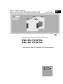
Passivhaus-Kompaktgerät mit easyControls
KWL EC 270 W R/L
KWL EC 370 W R/L
- Wärmerückgewinnung und EC-Technik
für zentrale Be- und Entlüftung.
DEUTSCH
Helios Ventilatoren
MONTAGE- UND BETRIEBSVORSCHRIFT
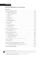
Inhaltsverzeichnis
KAPITEL 1. ALLGEMEINE MONTAGE- UND BETRIEBSHINWEISE . . . . . . . . . . . . . . . . . . . . . . . . . . . . . . . . . . .Seite 1
1.0 Allgemeine Informationen . . . . . . . . . . . . . . . . . . . . . . . . . . . . . . . . . . . . . . . . . . . . . . . . . . . . . . . . . . . . . . . .Seite 1
1.1 Warn- und Sicherheitshinweise . . . . . . . . . . . . . . . . . . . . . . . . . . . . . . . . . . . . . . . . . . . . . . . . . . . . . . . . . . .Seite 1
1.2 Wichtige technische Information . . . . . . . . . . . . . . . . . . . . . . . . . . . . . . . . . . . . . . . . . . . . . . . . . . . . . . . . . .Seite 1
1.3 Gewährleistung- und Haftungsansprüche . . . . . . . . . . . . . . . . . . . . . . . . . . . . . . . . . . . . . . . . . . . . . . . . . . .Seite 1
1.4 Vorschriften – Richtlinien . . . . . . . . . . . . . . . . . . . . . . . . . . . . . . . . . . . . . . . . . . . . . . . . . . . . . . . . . . . . . . . .Seite 1
1.5 Sendungsannahme . . . . . . . . . . . . . . . . . . . . . . . . . . . . . . . . . . . . . . . . . . . . . . . . . . . . . . . . . . . . . . . . . . . .Seite 1
1.6 Einlagerung . . . . . . . . . . . . . . . . . . . . . . . . . . . . . . . . . . . . . . . . . . . . . . . . . . . . . . . . . . . . . . . . . . . . . . . . . .Seite 1
1.7 Transport . . . . . . . . . . . . . . . . . . . . . . . . . . . . . . . . . . . . . . . . . . . . . . . . . . . . . . . . . . . . . . . . . . . . . . . . . . . .Seite 1
1.8 Einsatzbereich – Anwendung . . . . . . . . . . . . . . . . . . . . . . . . . . . . . . . . . . . . . . . . . . . . . . . . . . . . . . . . . . . . .Seite 2
1.9 Funktion und Wirkungsweise . . . . . . . . . . . . . . . . . . . . . . . . . . . . . . . . . . . . . . . . . . . . . . . . . . . . . . . . . . . . .Seite 2
1.10 Leistungsdaten . . . . . . . . . . . . . . . . . . . . . . . . . . . . . . . . . . . . . . . . . . . . . . . . . . . . . . . . . . . . . . . . . . . . . . .Seite 2
1.11 Feuerstätten . . . . . . . . . . . . . . . . . . . . . . . . . . . . . . . . . . . . . . . . . . . . . . . . . . . . . . . . . . . . . . . . . . . . . . . . .Seite 2
1.12 Technische Daten . . . . . . . . . . . . . . . . . . . . . . . . . . . . . . . . . . . . . . . . . . . . . . . . . . . . . . . . . . . . . . . . . . . . .Seite 3
1.13 RJ-Anschlüsse mit easyControls . . . . . . . . . . . . . . . . . . . . . . . . . . . . . . . . . . . . . . . . . . . . . . . . . . . . . . . . . .Seite 3
1.14 Wichtige Gerätekomponenten . . . . . . . . . . . . . . . . . . . . . . . . . . . . . . . . . . . . . . . . . . . . . . . . . . . . . . . . . . . .Seite 4
KAPITEL 2. MONTAGE . . . . . . . . . . . . . . . . . . . . . . . . . . . . . . . . . . . . . . . . . . . . . . . . . . . . . . . . . . . . . . . . . . . . . .Seite 5
2.0 Aufstellung . . . . . . . . . . . . . . . . . . . . . . . . . . . . . . . . . . . . . . . . . . . . . . . . . . . . . . . . . . . . . . . . . . . . . . . . . . .Seite 5
2.1 Wandmontage . . . . . . . . . . . . . . . . . . . . . . . . . . . . . . . . . . . . . . . . . . . . . . . . . . . . . . . . . . . . . . . . . . . . . . . .Seite 5
2.2 Kondensatablauf . . . . . . . . . . . . . . . . . . . . . . . . . . . . . . . . . . . . . . . . . . . . . . . . . . . . . . . . . . . . . . . . . . . . . .Seite 6
2.3 Anschlussstutzen . . . . . . . . . . . . . . . . . . . . . . . . . . . . . . . . . . . . . . . . . . . . . . . . . . . . . . . . . . . . . . . . . . . . . .Seite 7
2.4 Luftführung, Lüftungsleitung . . . . . . . . . . . . . . . . . . . . . . . . . . . . . . . . . . . . . . . . . . . . . . . . . . . . . . . . . . . . .Seite 7
2.5 Gerätedämmung . . . . . . . . . . . . . . . . . . . . . . . . . . . . . . . . . . . . . . . . . . . . . . . . . . . . . . . . . . . . . . . . . . . . . .Seite 7
2.6 Elektrischer Anschluss . . . . . . . . . . . . . . . . . . . . . . . . . . . . . . . . . . . . . . . . . . . . . . . . . . . . . . . . . . . . . . . . . .Seite 7
KAPITEL 3. FUNKTIONSBESCHREIBUNG . . . . . . . . . . . . . . . . . . . . . . . . . . . . . . . . . . . . . . . . . . . . . . . . . . . . . .Seite 8
3.0 Funktionsschema . . . . . . . . . . . . . . . . . . . . . . . . . . . . . . . . . . . . . . . . . . . . . . . . . . . . . . . . . . . . . . . . . . . . .Seite 8
3.1 Erstinbetriebnahme und Einregulierung . . . . . . . . . . . . . . . . . . . . . . . . . . . . . . . . . . . . . . . . . . . . . . . . . . . . .Seite 8
3.2 Bypassfunktion „ Sommerbetrieb“ . . . . . . . . . . . . . . . . . . . . . . . . . . . . . . . . . . . . . . . . . . . . . . . . . . . . . . . . .Seite 9
KAPITEL 4. SERVICE UND WARTUNG . . . . . . . . . . . . . . . . . . . . . . . . . . . . . . . . . . . . . . . . . . . . . . . . . . . . . . . .Seite 10
4.0 Service und Wartung . . . . . . . . . . . . . . . . . . . . . . . . . . . . . . . . . . . . . . . . . . . . . . . . . . . . . . . . . . . . . . . . . .Seite 10
4.1 Kreuzgegenstrom-Wärmetauscher . . . . . . . . . . . . . . . . . . . . . . . . . . . . . . . . . . . . . . . . . . . . . . . . . . . . . . .Seite 10
4.2 Filterwechsel . . . . . . . . . . . . . . . . . . . . . . . . . . . . . . . . . . . . . . . . . . . . . . . . . . . . . . . . . . . . . . . . . . . . . . . .Seite 10
4.3 Kondensatablauf im Gerät . . . . . . . . . . . . . . . . . . . . . . . . . . . . . . . . . . . . . . . . . . . . . . . . . . . . . . . . . . . . . .Seite 11
4.4 Zugang zum internen Klemmenkasten . . . . . . . . . . . . . . . . . . . . . . . . . . . . . . . . . . . . . . . . . . . . . . . . . . . . .Seite 11
4.5 Demontage EPS-Innenkorpus . . . . . . . . . . . . . . . . . . . . . . . . . . . . . . . . . . . . . . . . . . . . . . . . . . . . . . . . . . .Seite 11
4.6 Montage EPS-Innenkorpus mit Motoreinheit . . . . . . . . . . . . . . . . . . . . . . . . . . . . . . . . . . . . . . . . . . . . . . . .Seite 12
4.7 Sonstiges Zubehör . . . . . . . . . . . . . . . . . . . . . . . . . . . . . . . . . . . . . . . . . . . . . . . . . . . . . . . . . . . . . . . . . . .Seite 12
4.8 Anschlussbaugruppen mit Erweiterungsmodul für externe Heizregister . . . . . . . . . . . . . . . . . . . . . . . . . . . .Seite 12
KAPITEL 5. ABMESSUNGEN . . . . . . . . . . . . . . . . . . . . . . . . . . . . . . . . . . . . . . . . . . . . . . . . . . . . . . . . . . . . . . . .Seite 13
5.0 Abmessungen . . . . . . . . . . . . . . . . . . . . . . . . . . . . . . . . . . . . . . . . . . . . . . . . . . . . . . . . . . . . . . . . . . . . . . .Seite 13
5.1 Gerätetypenschild . . . . . . . . . . . . . . . . . . . . . . . . . . . . . . . . . . . . . . . . . . . . . . . . . . . . . . . . . . . . . . . . . . . .Seite 13
KAPITEL 6. ABMESSUNGEN . . . . . . . . . . . . . . . . . . . . . . . . . . . . . . . . . . . . . . . . . . . . . . . . . . . . . . . . . . . . . . . .Seite 14
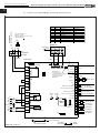
6.0 Standard Anschlussplan SS-1044 . . . . . . . . . . . . . . . . . . . . . . . . . . . . . . . . . . . . . . . . . . . . . . . . . . . . . . . .Seite 14
6.1 Verdrahtungsplan KWL EC... W . . . . . . . . . . . . . . . . . . . . . . . . . . . . . . . . . . . . . . . . . . . . . . . . . . . . . . . . . .Seite 15
6.2 Verdrahtungsplan KWL EC... W . . . . . . . . . . . . . . . . . . . . . . . . . . . . . . . . . . . . . . . . . . . . . . . . . . . . . . . . . .Seite 16
KAPITEL 7. HÄUFIGE FRAGEN . . . . . . . . . . . . . . . . . . . . . . . . . . . . . . . . . . . . . . . . . . . . . . . . . . . . . . . . . . . . . .Seite 17
7.0 Häufige Fragen . . . . . . . . . . . . . . . . . . . . . . . . . . . . . . . . . . . . . . . . . . . . . . . . . . . . . . . . . . . . . . . . . . . . . .Seite 17
Dieses Produkt enthält Batterien bzw. Akkus. Nach dem Batteriegesetz (BattG) sind wir verpflichtet, auf Folgendes hinzuweisen:
Batterien und Akkus dürfen nicht im Hausmüll entsorgt werden. Sie sind zur Rückgabe gebrauchter Batterien und Akkus gesetzlich verpflichtet. Sie können Batterien
und Akkus im Handel oder in kommunalen Sammelstellen unentgeltlich zurückgeben.
Batterien oder Akkus, die Schadstoffe enthalten, sind mit einem Symbol einer durchgekreuzten Mülltonne gekennzeichnet. Unter dem Mülltonnen-Symbol befindet
sich die chemische Bezeichnung des Schadstoffes.
Cd für Cadmium, Pb für Blei und Hg für Quecksilber
Denken Sie an unsere Umwelt, mit der Rückgabe leisten Sie einen wesentlichen Beitrag zum Umweltschutz!
Montage- und Betriebsvorschrift
Passivhaus-Kompaktgeräte KWL EC 270/370 W R/L
D
Herzlichen Glückwunsch
zum Erwerb eines Premiumproduktes von Helios Ventilatoren. Als Helios Kunde profitieren Sie von der langjährigen Erfahrung des Unternehmens in der Branche und erhalten einen Artikel in Premiumqualität. Alle KWL EC 270/370 W R/L Geräte werden bereits bei der Produktion auf ihre Funktionsfähigkeit geprüft.
Dabei werden nicht nur die offensichtlichen Funktionen (z.B. Betrieb der Ventilatoren) getestet, sondern auch diese, bei welchen Sie als Kunde selbst keine
Tests durchführen können. Dazu zählen beispielsweise die interne und externe Leckage und die elektrische Sicherheit. Außerdem wird Ihnen durch innovative
Ideen im Bereich der Steuerungs- und Regelungstechnik eine Reduktion der Betriebskosten ermöglicht.
Sollten Sie unerwartet dennoch ein Problem mit unserm Gerät haben, können Sie sich an den Fachinstallateur oder unseren Helios Kundendienst wenden.
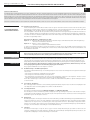
1.0 Allgemeine Informationen
KAPITEL 1
Zur Sicherstellung einer einwandfreien Funktion und zur eigenen Sicherheit sind alle nachstehenden Vorschriften genau
durchzulesen und zu beachten. National einschlägigen Normen, Sicherheitsbestimmungen und Vorschriften (z.B. DIN
EN VDE 0100) sowie die TAB des EVUs sind unbedingt zu beachten und anzuwenden.
Das Planungsbüro erstellt die für die Systemberechnung erforderlichen Planungsunterlagen. Zusätzliche Informationen
oder eine detaillierte Planung (kostenpflichtige Leistung) kann bei Helios angefragt werden. Die Montage- und Betriebsvorschrift als Referenz am Gerät aufbewahren. Nach der Endmontage muss dem Betreiber (Mieter/Eigentümer) das
Dokument ausgehändigt werden.
ALLGEMEINE MONTAGEUND BETRIEBSHINWEISE
Gliederung der Montage- und Betriebsvorschrift:
Kapitel 1 – 3 Allgemeine Montage, Betriebshinweise, Gerätemontage und Erstinbetriebnahme bzw. Einregulierung
– ist für den Fachinstallateur bestimmt
Kapitel 4 – 5 Zubehör + Service und Wartung
– ist für den Fachinstallateur und Endkunden bestimmt
In dem im Lieferumfang enthaltenen Anwender-Handbuch „ EasyControls“ (Nr. 82 200) sind alle Informationen zur
Bedienung und Steuerung der Kompaktgeräte zu finden. Dieses Anwender-Handbuch ist für den Fachinstallateur und
den Endkunden bestimmt.
1.1
Warn- und Sicherheitshinweise
Nebenstehendes Symbol ist ein sicherheitstechnischer Warnhinweis. Alle Sicherheitsvorschriften bzw. Symbole
müssen unbedingt beachtet werden, damit jegliche Gefahrensituation vermieden wird.
WICHTIG
☞
1.2
WARNUNG
Wichtige technische Information
Die KWL EC 270/370 W R/L besitzen einen Türkontaktschalter. Wird die frontseitige Tür entfernt, erfolgt eine allpolige
Trennung der Versorgungsspannung im geräteinternen Klemmenkasten. Somit sind normale Wartungsarbeiten z.B.:
Überprüfung Kondensatablauf, Filterwechsel, Reinigung Wärmetauscher, Montage der Vorheizung (Zubehör) möglich.
Sollte der geräteinterne Klemmenkasten geöffnet werden (z.B.: Sicherungstausch, Batterietausch), muss die
Versorgungsspannung direkt in der Zuleitung allpolig getrennt werden!
Die geeigneten Maßnahmen sind in Kapitel 2 zu finden.
1.3
Gewährleistungs- und Haftungsansprüche
Zur Wahrung der Gewährleistungs- und Haftungsansprüche des Kunden sind zwingend nachfolgende Ausführungen
zu beachten:
– Umsetzung nach Montage und Betriebsvorschrift „ Gerät“
– Umsetzung nach Anwender-Handbuch „ EasyControls”
– Die Verwendung von Zubehörteilen, die nicht von Helios freigegeben, empfohlen oder angeboten werden, ist nicht
zulässig. Eventuell auftretende Schäden unterliegen nicht der Gewährleistung.
Wenn diese Ausführungen nicht beachtet werden, entfällt unsere Gewährleistung. Gleiches gilt für Haftungsansprüche
an den Hersteller.
1.4
Vorschriften – Richtlinien
Bei ordnungsgemäßer Installation und bestimmungsgemäßem Betrieb entspricht das Passivhaus-Kompaktgerät den
zum Zeitpunkt seiner Herstellung gültigen Vorschriften und CE-Richtlinien.
1.5
Sendungsannahme
Die Lieferung enthält den Gerätetyp: KWL EC 270 W R/L oder KWL EC 370 W R/L
Die Sendung ist sofort bei Anlieferung auf Beschädigungen und Typenrichtigkeit zu prüfen. Falls Schäden vorliegen,
unverzüglich Schadensmeldung unter Hinzuziehung des Transportunternehmens veranlassen. Bei nicht fristgerechter
Reklamation gehen evtl. Ansprüche verloren.
1.6
Einlagerung
Bei Einlagerung über einen längeren Zeitraum sind zur Verhinderung schädlicher Einwirkungen folgende Maßnahmen zu
treffen: Schutz durch trockene, luft- und staubdichte Verpackung (Kunststoffbeutel mit Trockenmittel und Feuchtigkeitsindikatoren). Der Lagerort muss erschütterungsfrei, wassergeschützt und frei von übermäßigen Temperaturschwankungen sein. Schäden, deren Ursprung in unsachgemäßem Transport, unsachgemäßer Einlagerung oder Inbetriebnahme liegen, sind nachweisbar und unterliegen nicht der Gewährleistung.
1.7
Transport
Das Gerät ist werkseitig so verpackt, dass es gegen normale Transportbelastungen geschützt ist. Führen Sie den
Transport sorgfältig durch. Es wird empfohlen, das Gerät bis zur Aufstellung in der Originalverpackung zu belassen, um
mögliche Beschädigungen und Verschmutzungen zu vermeiden.
1
Montage- und Betriebsvorschrift
Passivhaus-Kompaktgeräte KWL EC 270/370 W R/L
D
WICHTIG
1.8
Einsatzbereich – Anwendung
Kompaktgeräte KWL EC 270/370 W mit Wärmerückgewinnung, für die zentrale Be- und Entlüftung von Geschosswohnungen und kleinen Einfamilienhäusern auch im Passivhaus-Standard (PHI). Ausgestattet mit easyControls, dem innovativen Steuerungskonzept für einfachste Netzwerkanbindung und Webbrowser-Bedienung. Mit hocheffizientem
Kreuzgegenstrom-Wärmetauscher aus Kunststoff.
Die serienmäßige Ausstattung erlaubt die Aufstellung und den Einsatz in frostfreien Räumen über +5 °C. Bei Betrieb
unter erschwerten Bedingungen, wie z.B. hohe Feuchtigkeit, längere Stillstandzeiten, starke Verschmutzung, übermäßige Beanspruchung durch klimatische sowie technische, elektronische Einflüsse, ist eine Rückfrage und Einsatzfreigabe erforderlich, da die Serienausführung hierfür u. U. nicht geeignet ist.
Ein bestimmungsfremder Einsatz ist nicht zulässig!
1.9
Funktion und Wirkungsweise
Das KWL-Kompaktgerät besitzt einen Kreuz-Gegenstromwärmetauscher aus Kunststoff, in welchem sich die Außenluft
(Frischluft) und die Gebäudeabluft kreuzen, ohne direkt miteinander in Verbindung zu kommen. Hierbei gibt die Abluft
den größten Teil der Wärme an die Außenluft ab. Die Zuluft wird durch das Rohrsystem zu den Zuluft benötigenden
Räumen (Wohn- und Schlafräume) geleitet. Die Abluft wird aus den untergeordneten Räumen (wie z.B. Küche, Toiletten, Duschen u.v.m.) abgesaugt. Sie strömt durch das Rohrsystem zum Lüftungsgerät zurück, gibt Wärme ab und wird
durch die Fortluftleitung ins Freie geführt.
Der Wärmebereitstellungsgrad hängt von den Faktoren Feuchte der Luft und Temperaturunterschied der Außenluft und
Abluft ab. Der Volumenstrom kann über den im Lieferumfang enthaltenen lokalen WEB-Server (LAN-Anschluss) als
auch über die (optional erhältlichen) Bedienelemente KWL-BE oder KWL-BEC geregelt werden.
Eine bedarfsgerechte Regelung kann durch die optionalen Fühler KWL-VOC = Luftqualitätsfühler, KWL-CO2 = Kohlendioxid-Fühler oder KWL-FTF = Feuchte-Temperatur-Fühler oder durch die integrierte Wochenzeitschaltuhr erfolgen.
☞
Die elektrische Vorheizung EHR-R 1,2/160 (Zubehör, Best-Nr. 9434) erwärmt die Außenluft und verhindert bei sehr
niedrigen Außentemperaturen eine Vereisung des Wärmetauschers und garantiert dessen sichere Funktion für eine
optimale Wärmerückgewinnung im Winter. Fortlufttemperatur einstellbar von 0 °C bis +10 °C. Durch Ansteuerung einer
leistungsgeregelten, externen Elektro- oder Warmwasser-Nachheizung (Zubehör EHR-R...oder WHR...) kann auch die
Zulufttemperatur zusätzlich erwärmt werden.
Für warme Jahreszeiten ist der Sommer-Bypass die optimale Lösung, um kühlere Außenluft in das Gebäude zu leiten.
Durch die integrierten Filter wird die Luft optimal gereinigt. Dies sorgt für ein hygienisches Gerät. Serienmäßig ist in der
Außenluft ein G4-Filter und in der Abluft ein G4-Filter eingebaut. Optional kann zusätzlich ein F7-Filter in den Zuluftbereich nach dem Wärmetauscher eingesetzt werden. Voraussetzung für eine dauerhafte einwandfreie Funktion des Lüftungsgerätes ist jedoch der regelmäßige Filtertausch und Wartung des KWL-Gerätes.
T IP P !
Ersatzluftfilter können im Internet unter www.ersatzluftfilter.de bestellt werden.
1.10 Leistungsdaten
Um die geplanten Leistungsdaten (z.B. optimaler Volumenstrom, geringer Schall und Stromaufnahme) zu erreichen, ist
auf eine korrekt geplante und ausgeführte Luftverteilung (Außenluft/Zuluft und Abluft/Fortluft) zu achten. Des Weiteren
muss diese entsprechend dimensioniert sein.
T IP P !
Helios bietet regelmäßig Praxisworkshops zu diesem Thema an, in welchen praxisnah zur Planung und Installation alle
wichtigen Details vermittelt werden. Die Termine sind auf unserer Website www.heliosventilatoren.de unter Schulung.
Schlechte Ausführungen, ungünstige Einbau- und Betriebsbedingungen können zu einer Reduzierung der Förderleistung oder zu einem erhöhten Schallpegel führen. Die Angaben für das luftseitige Geräusch erfolgen als A-bewerteter
Schallleistungspegel LWA (entspricht DIN 45635, T.1). Angaben in A-bewertetem Schalldruck LPA werden von raumund installationsspezifischen Gegebenheiten beeinflusst. Dadurch können Abweichungen zu den Angaben auftreten.
WICHTIG
☞
1.11 Feuerstätten
Die einschlägig geltenden Vorschriften für den gemeinsamen Betrieb von Feuerstätte, Wohnungslüftung, Dunstabzugshaube (Info über den Bundesverband des Schornsteinfegerhandwerks-Zentralinnungsverband (ZIV)) sind
zu beachten!
WICHTIG
☞
– Allgemeine baurechtliche Anforderungen
Die KWL-Geräte mit Wärmerückgewinnung dürfen nur dann in Räumen mit anderen raumluftabhängigen Feuerstätten
installiert und betrieben werden, wenn deren Abgasabführung durch besondere Sicherheitseinrichtungen (bauseits)
überwacht wird, die im Auslösefall das KWL-Gerät spannungslos schalten. Das KWL-Gerät wird solange ausgeschaltet
bis die Feuerstätte nicht mehr aktiv ist. Dabei muss sichergestellt werden, dass durch den Betrieb der KWL-Geräte kein
größerer Unterdruck als 4 Pa in der Wohneinheit erzeugt wird.
Das KWL-Gerät darf nicht gleichzeitig mit Festbrennstoff-Feuerstätten und nicht in Wohneinheiten mit raumluftabhängigen Feuerstätten, die an mehrfach belegte Abgasanlagen angeschlossen sind, betrieben werden. Für den bestimmungsgemäßen Betrieb der mit einem Lüftungsgerät mit Wärmerückgewinnung errichteten Lüftungsanlage müssen
eventuell vorhandene Verbrennungsluftleitungen sowie Abgasanlagen von Festbrennstoff-Feuerstätten absperrbar sein.
2
Montage- und Betriebsvorschrift
Passivhaus-Kompaktgeräte KWL EC 270/370 W R/L
D
Wir empfehlen vor der Beschaffung eines Unterdruck-Überwachungssystem für Feuerstätten mit dem zuständigen
T IP P ! Schornsteinfeger zu sprechen, um eventuelle Wünsche zu berücksichtigen.
1.12 Technische Daten
KWL EC 270 W R/L
Spannung/Frequenz
Nennstrom – Lüftungsbetrieb
Vorheizung (Ausgang) kW
Sommer Bypass
Elektrische Zuleitung bis UV
Förderleistungen Vm3/h (3 Stufen)
1~ 230 V~/50 Hz
1,0 A
1,0 kW
auto (einstellbar)
NYM-J 3 x 1,5 mm2
285 / 170 / 110
Anschluss nach Schaltplan
Temperatur Arbeitsbereich
Gewicht Rohbauset
Standby-Verluste
Ausführung in
Temperatur Aufstellbereich
SS-1044
-20 °C bis +40 °C
49 kg
<1W
IP20
+5 °C bis +40 °C
KWL EC 370 W R/L
Spannung/Frequenz
Nennstrom – Lüftungsbetrieb
Vorheizung (Ausgang) kW
Sommer Bypass
Elektrische Zuleitung bis UV
Förderleistungen Vm3/h (3 Stufen)
1~ 230 V~/50 Hz
2,2 A
1,0 kW
auto (einstellbar)
NYM-J 3 x 1,5 mm2
350 / 200 / 140
Anschluss nach Schaltplan
Temperatur Arbeitsbereich
Gewicht Rohbauset
Standby-Verluste
Ausführung in
Temperatur Aufstellbereich
SS-1044
-20 °C bis 40 °C
52 kg
<1W
IP20
+5 °C bis +40 °C
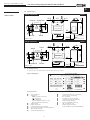
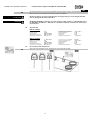
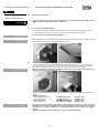
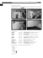
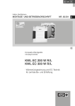
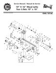
1.13 RJ-Anschlüsse mit easyControls
T IP P ! Anwender-Handbuch (Nr. 82 200) „ EasyControls” beachten
Abb.1
RJ45
RJ12
RJ10
Steuerleitung RJ10 ( digital )
WARNUNG
Überwachungssysteme werden immer in der Gerätezuleitung eingebunden!
(siehe Schaltplan SS-1044; Position Nr.1)
ACHTUNG LEBENSGEFAHR! Die Verwendung des externen Kontaktes (Funktion 1; Gerät Ein- /Ausschalten) des
KWL-EM oder der KWL-CO2 / KWL-VOC als Abschaltung für Unterdruck-Überwachung ist nicht zulässig.
Steuerleitung RJ12 ( Analog )
TCP/IP Verbindung
ACHTUNG
3
Abb.2
Montage- und Betriebsvorschrift
Passivhaus-Kompaktgeräte KWL EC 270/370 W R/L
D
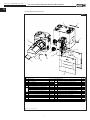
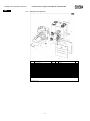
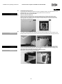
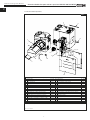
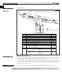
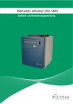
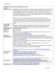
1.14 Wichtige Gerätekomponenten
Abb.3
L
GM
GN
H
G
GG
MBòNBòOBòGF
GG
K
GL
I
G
HH
GK
ambò[YòHMFEIMFòmòh{y~Eb
f
D X{{}
G \{ò]Jòp|
H \{ò]JòXw
I m
{wy~{
J CCCCC
K c
{~{òDòfhe
© c
{~{ò>ambò[YòHMFòmòh{y~?
© c
{~{ò>ambò[YòHMFòmòb?
© c
{~{ò>ambò[YòIMFòmòh{y~?
© c
{~{ò>ambò[YòIMFòmòb?
L h`òWzw{Cfw{
M XWi_YCfw{òòa~{
N iy~{}òjPò\HWbHKFlòCòKHFò>\òHJl?
O iy~{}òjPòjJW^HKFlòCòKHFò>\òHIFl?
GF Xw{{òjPòYhHFIHòCòIl
C CCCCC
C CCCCC
Abb.: rechte Geräteausführung
4
WDCdD
FOLGI
FOLGM
NJLOK
CCCCC
CCCCC
NKKFG
NKLMK
NKLML
NKKFH
GNIJI
NHOGM
NKMIM
NKMIN
NJMFK
CCCCC
CCCCC
f
D X{{}
GG hwzw{w
© hwzw{w
òÂòGJFò>ambò[YòHMF?
© hwzw{w
òÂòGLFò>ambò[YòIMF?
GH CCCCC
GI CCCCC
GJ CCCCC
GK ]{~
{{
© ]{~
{ò>ambò[YòHMFEIMFòmòh{y~?
© ]{~
{ò>ambò[YòHMFEIMFòmòb?
GL a}{~
GM mwzx{|{}}y~{{òex{
GN mwzx{|{}}y~{{òk{
GO CCCCC
HF CCCCC
HG CCCCC
HH a
z{wwxw|y~wy~
WDCdD
CCCCC
NJMFM
NJMFN
CCCCC
CCCCC
CCCCC
CCCCC
NKKGJ
NKKGK
NJOGJ
NJMGK
NJMGL
CCCCC
CCCCC
CCCCC
NHFIO
Montage- und Betriebsvorschrift
Passivhaus-Kompaktgeräte KWL EC 270/370 W R/L
D
KAPITEL 2
2.0
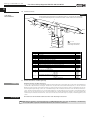
Aufstellung
Das KWL-Kompaktgerät ist für die „ hängende“ Anordnung zur Installation an der Wand oder zum Einbau in einen
Schrank konzipiert und somit für eine Installation innerhalb der Wohnung/Raumeinheit vorgesehen. Aufgrund der
Betriebsgeräusche, wird empfohlen das KWL-Gerät in einem untergeordneten Raum (Waschraum, Flur, Technikraum,
Abstellraum) aufzustellen. Darauf achten, dass im Installationsbereich ein Abwasseranschluss vorhanden ist. Hierzu
auch Hinweise von Punkt 2.2 “Kondensatablauf“ beachten!
Die Montage soll so erfolgen, dass möglichst kurze Lüftungsleitungen sowie deren problemloser Anschluss an das
Gerät möglich sind. Enge Bögen führen zu erhöhten Druckverlusten und Strömungsgeräuschen. Die Lüftungsleitungen
dürfen keinesfalls geknickt werden. Auf feste und dichte Befestigung an den Anschlussstutzen ist zu achten. Für Wartungs- und Installationsarbeiten muss das Gerät bzw. Klemmenkasten frei zugänglich sein.
Wichtige Hinweise:
1. Klemmenkasten bei rechter Geräteausführung auf der linken Seite zugänglich, bei linker Geräteausführung
auf der rechten Seite.
2. Wird eine Vorheizung bzw. Nachheizung verbaut, muss das Rohr mind. 1 m vor und nach dem Heizregister
aus nicht brennbarem Material sein (siehe Funktionsschema Abb.17).
3. Die Heizung muss so eingebaut sein, dass der Elektrokasten leicht zugänglich ist.
4. Um Schallübertragungen zu vermeiden, muss je nach Bausubstanz bauseits eine geeignete Schallentkopplung vorgesehen werden.
5. Bei der Aufstellung des KWL-Kompaktgerätes, muss ein ausreichend zugänglicher Revisionsraum vorgesehen werden.
6. Die Aufstellung darf nur in frostfreien Räumen erfolgen, da die Gefahr des Einfrierens besteht. Die Raumtemperatur darf nicht unter +5 °C sinken.
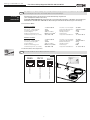
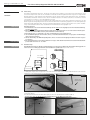
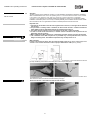
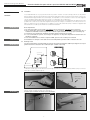
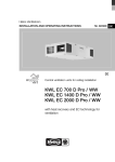
2.1
Wandmontage
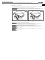
Zur Wandbefestigung des Gerätes die Mindesthöhe von mindestens 300 mm bis Unterkante Lüftungsgerät einhalten um einen ordnungsgemäßen Kondensatablauf zu gewährleisten (siehe Abb. unten).
MONTAGE
WICHTIG
☞
ACHTUNG
WICHTIG
☞
%RGHQDEVWDQG
PLQGPP
PLQGPP
PLQGPP
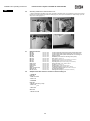
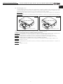
1. Beiliegende Trageschiene waagerecht an der Wand montieren (Abb.4). Anschließend die Wandschiene (im Lieferumfang) unten an der Rückwand des Kompaktgerätes fest schrauben (Abb.5).
Abb.5
Abb.4
Wandschiene
festschrauben
Trageschiene
ACHTUNG
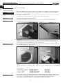
2. Kompaktgerät in die Trageschiene einhängen. Die obere Trageschiene an der Rückseite des KWL-Geräts ist bereits
vormontiert (Abb.6).
Anschließend das Gerät mit der Wandbefestigungsschiene an der Wand fest schrauben (Abb.7).
Sicherstellen, dass das Gerät mit beiden Wandschienen an der Wand montiert wird!
Abb.6
Geräteunterseite
Abb.7
Wand
5
Montage- und Betriebsvorschrift
Passivhaus-Kompaktgeräte KWL EC 270/370 W R/L
D
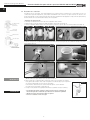
2.2
Kondensatablauf
Während der Heizperiode kondensiert die Feuchtigkeit der Abluft zu Wasser. In Neubauten oder beim Baden, beim
Kochen sowie beim Wäschetrocknen kann sich reichlich Kondenswasser bilden. Das Kondenswasser muss frei aus
dem Gerät ablaufen können. Hierzu muss der beiliegende Kugelsiphon (Lieferumfang) in der Kondensatöffnung der
Bodenwanne montiert werden.
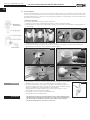
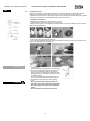
– Montage Kugelsiphon
Die Montage erfolgt direkt in der Bodenwanne des Gerätes.
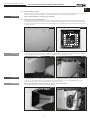
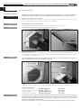
1. Kugelsiphon öffnen, hierzu das Befestigungsteil durch 1/4 Drehung aufdrehen (Abb.8).
2. Befestigungsteil von unten in die Kondensatöffnung stecken, bis die Krallen an der Blechkante der Bodenplatte einrasten (Abb.9)
Abb.9
Abb.8
3. Verriegelungsteil einführen und nach oben schieben (Abb.10).
4. Anschließend beigelegten Kondensatschlauch DN 12 mm (Länge nach Bedarf) auf den Schlauchverbinder des
Siphon-Gehäuses aufstecken und von Hand festschrauben (Abb.11).
Abb.10
Kondensatschlauch auf Verbinder aufstecken
Abb.11
Verriegelungsteil einführen
Abb.12
Abb.13
Siphon-Gehäuse
aufstecken
1/4 Drehung
Kondensatschlauch DN 12 mm
(Gefälle beachen!)
WICHTIG
☞
ACHTUNG
5. Siphon-Gehäuse aufstecken und mit 1/4 Drehung im Befestigungsteil einrasten (Abb.12)
(HINWEIS: Darauf achten, dass die Schwimmer-Kugel lose im Gehäuse liegt!)
6. Kondensatschlauch DN 12 mm (Länge nach Bedarf) an das Entwässerungssystem
Siphon
des Hauses (Siphon) anschließen. Dabei den Kondensatschlauch mit Gefälle verlegen
(Abb.13). Unabdingbar für ordnungsgemäßen Kondensatablauf.
Aufgrund der Geruchsentwicklung bei einem ausgetrockneten Siphon, sollte ein
offener Abfluss verbaut werden (Skizze Abb.14).
7. Der Kugelsiphon muss kontrolliert und gereinigt werden
(Wartungsintervall wie bei Filterwartung).
– Der Kugelsiphon darf bei bauseitiger Montage keinen seitlichen Belastungen
durch den Kondensatschlauch ausgesetzt sein, um Dichtheit zu gewährleisten!
– Der Rohrverlauf der Kanalisation darf hinter dem Siphon nicht ansteigen!
– Der Kondensatablauf muss frostsicher verlegt sein!
6
Abb.14
Montage- und Betriebsvorschrift
Passivhaus-Kompaktgeräte KWL EC 270/370 W R/L
D
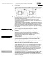
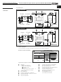
Anschlussstutzen
Die Geräte sind mit vier Stutzen (Durchmesser 160 mm) ausgerüstet. Die Rohrleitungen (z.B. IsoPipe IP-160) müssen
fest und dicht an die Stutzen angeschlossen werden, hierzu ist der Rohrverbinder RVBD 160 (Best.-Nr. 9641) zu verwenden. Die Anordnung der Lüftungsleitung ist je nach Geräteausführung aus den Abb. 15/16 zu entnehmen.
GFMBK
\
| W{|
Abb.15
linkes
Geräte
ACHTUNG
WARNUNG
Wx|
W{|
\
|
2.4
Luftführung, Lüftungsleitung
Bei Planung und Ausführung sind möglichst kurze Leitungen anzustreben. Auf dichte Verbindungen und Übergänge ist
zu achten. Zur Vermeidung von Schmutzablagerung, hohem Druckverlust und starken Geräuschen sind glattwandige
Rohre zu verwenden. Für Hauptleitungen (Außen-, Fortluft, Zuluftverteiler, Abluftsammler) ist folgender Rohrdurchmesser
– KWL EC 270 W R/L > DN 160 mm (z.B. Isoliertes Rohrsystem Iso-Pipe IP-160, Zubehör)
– KWL EC 370 W R/L > DN 160 mm (z.B. Isoliertes Rohrsystem Iso-Pipe IP-160, Zubehör)
vorzusehen, für Stichleitungen kann der ø entsprechend reduziert werden.
Die Zuluft ist den Wohn- und Schlafräumen zuzuführen, die Abluft in den Nutzräumen abzuführen. Zur Vermeidung von
Kondensat an den Außen- und Fortluftleitungen sowie eventuell vorhandenen Vorheizregistern und Filterboxen sind
diese in geeigneter Weise bauseits zu dämmen. Die Mindestdämmstärken lt. DIN EN 1946-6, 05/2009 sind einzuhalten. Verlaufen Zu- und Abluftleitungen durch unbeheizte Räume, so sind sie zur Vermeidung von Wärmeverlusten ebenfalls zu dämmen.
Zur Einregulierung der Anlage sollten Zu- und Abluftöffnungen mit einstellbaren Ventilen (Zubehör) versehen werden.
Bei Absaugung von verschmutzter Abluft ist ein Filter (Zubehör) vorzuschalten. Dunstabzugshauben dürfen nicht an das
System angeschlossen werden (Gründe: Schmutz, Brandgefahr, Hygiene). Zur Sicherstellung der Luftführung innerhalb
der Raumeinheit sind ausreichende Überströmöffnungen (Türspalte, Türlüftungsgitter) vorzusehen.
Evtl. bestehende Brandschutzvorschriften sind unbedingt zu beachten.
2.5
Gerätedämmung
Bei Aufstellung in beheizten Räumen und höherer Luftfeuchtigkeit kann es im Bereich der Außen- und Fortluft an der
Außenseite des Gerätes zu Kondensation kommen. In diesem Fall ist in diesem Bereich eine dampfdiffusionsdichte
Dämmung flächig anzubringen. Des Weiteren müssen die Außen- und Fortluftleitungen bauseits ausreichend gedämmt
werden.
Bei Aufstellung in nichtbeheizten Bereichen (z.B. frostfreien Spitzboden) ist ganzseitig eine ausreichende Dämmung
außen am Gerät anzubringen. Ansonsten könnte es zu Kondensatanfall an den Gehäuseseiten kommen. Die Kondensatableitung muss frostsicher verlegt werden, eventuell mit einer Heizung.
p|
Front
òGKFò
òGKFò
Front
2.6
Elektrischer Anschluss
Vor allen Wartungs- und Installationsarbeiten oder vor Öffnen des Schaltraumes ist das Gerät allpolig vom Netz
zu trennen! Der elektrische Anschluss darf nur von einer autorisierten Elektrofachkraft entsprechend den nachstehenden Anschlussplänen ausgeführt werden. Die einschlägigen Normen, Sicherheitsbestimmungen (z.B.
DIN VDE 0100) sowie die TAB der EVUs sind unbedingt zu beachten.
Wird der geräteinterne Klemmenkasten geöffnet (z.B. Sicherungstausch, Batterietausch etc.), muss das KWLGerät allpolig vom Netz getrennt werden!
– Gerät fünf Minuten abkühlen lassen bzw. warten, bis die Gebläse ausgedreht sind.
– Gefährdung durch elektrischen Schlag, bewegliche Teile (Gebläse) und heiße Oberflächen.
Laut DIN EN 60335-1 / VDE 0700 T1 7.12.1 muss ein Haupt- und Revisionsschalter (Zubehör RHS 3+1 Best.-Nr. 1594)
oder ein Fehlerstromschutzschalter Type: FI 300 mA 2 Typ B oder B+ in die Gerätezuleitung integriert werden, hierbei ist
die mind. Anforderung 3 mm Kontaktöffnung einzuhalten. Der Haupt- und Revisionsschalter bzw. der FI muss mit
geeigneten Mitteln gegen Wiedereinschalten gesichert werden.
Die KWL EC 270/370 W R/L Typen besitzen einen Türkontaktschalter. Wird die Fronttüre entfernt, erfolgt eine allpolige
Trennung der Versorgungsspannung im geräteinternen Klemmenkasten. Somit sind normale Wartungsarbeiten (Überprüfung Kondensatablauf, Filterwechsel, Reinigung Wärmetauscher, Montage der Vorheizung (Zubehör)) möglich. Der
Besitzer darf Wartungsarbeiten am Gerät durchführen.
WICHTIGER HINWEIS
☞
Bitte die Schaltpläne dem Installateur aushändigen!
Immer tiefe Unterputzdosen für die Bedienelemente bzw. die Fühler (KWL-CO2, KWL-VOC oder KWL-FTF) verwenden. Die Steuerleitung muss immer in einem Leerrohr M 25 verlegt werden. Es ist darauf zu achten, dass
die Verdrahtung in Reihe und nicht sternförmig erfolgen muss. Je nach Anzahl der Buskomponenten und Leitungslängen, muss eine abweichende Steuerleitung verbaut werden (siehe Schaltplan SS-1077 bzw. SS-1079).
7
ò
HFL
GII
òJNOò
Wand
HFL
Wand
Abb.16
p|
Wx|
ò
rechtes
Gerät
GII
òJNOò
2.3
Montage- und Betriebsvorschrift
Passivhaus-Kompaktgeräte KWL EC 270/370 W R/L
D
3.0
KAPITEL 3
Funktionsschema
Abb.17
FUNKTIONSBESCHREIBUNG
X{òl{{z}ò{{ò^{{}{Bòòzwòh
~{òGòò
òzòwy~òz{ò^{{}{
ò{{wx{
z}{òxDòy~òx{xw{òh
~ò{{~{ò{z{ò>DXDòmy{|w
~?
\
|
WÊ{|
I
jK
K
H
G
J
jL
GBòH
G
L
H
G
jG
Wx|
>jM?
hyw|
mmCh{}{
G
jI
jJ
jH
p|
G
òòòòòòòòòjGGCjGN
\{y~{Ej{{w|~{
>hw{}{ò_ww
?
WxxDòambò[YòHMFEIMFòmòb
f
D
jG
jH
jI
jJ
jK
jL
jM
jGGCjGN
G
H
I
J
K
X{{}
WDCdD
WÊ{||~{
p||~{
Wx||~{
\
||~{
aww|~{òòj{PòambCbjaòò>px{~?
aww|~{òòj{PòambCbjaòò>px{~?
\
y~|~{òòj{PòambCbjaòò>px{~?ò|òmmCh{}{òhyw|
\{y~{Ej{{w|~{òambC\j\
j{{wx{
z}{òòxDòy~òx{xw{òh
~ò>DXDòmy{|w
~?
j{{wx{
z}{òòxDòy~òx{xw{òZ
}
_
Cf{òh
~òÈGLF
l
~{}òòòòj{Pò[^hChòGBHEGLF
òòòòòòòòòòòòòòòòòòòòòòòòòòòòòòòòòòòòAòambC[c
òòòòòòòòòòòòòòòòòòòòòòòòòòòòòòòòòòòòAòambCbja
b||{CX
òj{Pòb\XhòGLFò]J
CCCCC
CCCCC
CCCCC
CCCCC
FOLJJ
FOLJJ
FOLJJ
FJHMI
CCCCC
CCCCC
[{y~{òdwy~~{}òòòòj{Pò[^hChòHBJEGLF
òòòòòòòòòòòòòòòòòòòòòòòòòòòòòòòòòòòòòòòòòòòòòòòòòòòòòòòòòòòòòòòòAòambC[c
òòòòòòòòòòòòòòòòòòòòòòòòòòòòòòòòòòòòòòòòòòòòòòòòòòòòòòòòòòòòòòòòAòambCbja
mww{òdwy~~{}òj{Pòm^hòGLF
W{w{ zò^zw{~{òòòòòòòòòòòòòòòòòòòòòAòm^i^òGGFFòHJlò>FCGFl?
òòòòòòòòòòòòòòòòòòòòòòòòòòòòòòòòòòòòòòòòòòòòòòòòòòòòòòòòòòòòòòòòAòambC[c
òòòòòòòòòòòòòòòòòòòòòòòòòòòòòòòòòòòòòòòòòòòòòòòòòòòòòòòòòòòòòòòòAòHòambCbjaò>jLAjM?
L
3.1
HINWEIS
ACHTUNG
FOJIJ
FJHLO
FOLJJ
FNKMN
FOJIK
FJHLO
FOLJJ
FOJNG
FNNGO
FJHLO
FOLJJ
Erstinbetriebnahme und Einregulierung
Nützlicher Hinweis zur Einregulierung!
In den Helios Praxisworkshops wird die Einregulierung mittels Druckmessung erklärt. Dies ist die einfachste Möglichkeit,
ein KWL EC 270/370 W R/L einzuregeln. Hierfür muss an jedem Anschlussstutzen/Lüftungsrohr (ca. 20 cm nach dem
Geräteanschluss) jeweils ein Druckmessstutzen montiert werden, die Druckschläuche müssen zugänglich verlegt sein.
Zur Einregulierung der Anlage sollten Zu- und Abluftöffnungen mit einstellbaren Elementen bzw. Ventilen (Zubehör) versehen werden. Bei Absaugung von verschmutzter Abluft ist ein Filter (Zubehör) vorzuschalten. Dunstabzugshauben
dürfen nicht an das System angeschlossen werden (Gründe: Schmutz, Brandgefahr, Hygiene). Zur Sicherstellung der
Luftführung innerhalb der Raumeinheit, sind ausreichende Überströmöffnungen (Türspalte, Türlüftungsgitter) vorzu
sehen.
Eventuell bestehende Brandschutzvorschriften sind unbedingt zu beachten!
T IP P !
Detaillierte Hinweise zur Einregulierung von KWL-Wandgeräten sind aus der Montage- und Betriebsvorschrift „KWL easyControls Erstinbetriebnahme”; Nr. 82 237 zu entnehmen!
8
Montage- und Betriebsvorschrift
Passivhaus-Kompaktgeräte KWL EC 270/370 W R/L
D
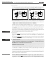
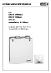
3.2
Bypassfunktion „Sommerbetrieb“
Die Bypassfunktion ermöglicht eine Reduzierung der Zulufttemperatur und sorgt durch Überbrücken des Wärmetauschers, mittels zweier gegenläufiger Bypassklappen, für ein angenehmes Raumklima.
Bypass geschlossen: Außenluft wird über Wärmetauscher in den Raum geleitet (Wärmerückgewinnung aktiv)
Bypass geöffnet: Außenluft wird direkt in den Raum geleitet (Wärmerückgewinnung inaktiv), indirektes Kühlen der
Raumluft
Abb.18
Abb.19
Bypassklappe geschlossen
Bypassklappe geöffnet
– Funktionsbeschreibung Bypass:
Wird das KWL mit Netzspannung versorgt, schließt die Bypassklappe vollständig (Abb.18).
Der Bypass wird geöffnet wenn alle Bedingungen erfüllt sind:
Bedingung 1: Die Ablufttemperatur (Fühler T3) ist höher als die Bypasstemperatur (Bypasstemperatur mind. +3 °C
höher als Zulufttemperatur siehe Nachheizung, Werkseinstellung +23 °C).
Bedingung 2: Die Außenlufttemperatur (Fühler T1) ist niedriger als die Ablufttemperatur (Fühler T3)
Bedingung 3: Die Außenlufttemperatur (Fühler T1) ist höher als die Außenluftbegrenzung (Werkseinstellung +15 °C)
Der Bypass wird geschlossen wenn Bedingung 4 und 5 oder 6 und 7 erfüllt sind.
Bedingung 4: Die Ablufttemperatur (Fühler T3) ist kleiner als die Bypasstemperatur die um -2 °C reduziert ist.
Bedingung 5: Der Bypass ist geöffnet
oder
Bedingung 6: Die Außenlufttemperatur (Fühler T1) ist niedriger als die Außenluftbegrenzung die um -2 °C reduziert ist.
Bedingung 7: Der Bypass ist geöffnet
9
Montage- und Betriebsvorschrift
Passivhaus-Kompaktgeräte KWL EC 270/370 W R/L
D
4.0
KAPITEL 4
SERVICE UND WARTUNG
WARNUNG
Service und Wartung
Vor allen Wartungs- und Installationsarbeiten oder vor Öffnen des Schaltraumes ist das Gerät allpolig vom
Netz zu trennen! Gefährdung durch elektrischen Schlag, bewegliche Teile (Gebläse) und heiße Oberflächen.
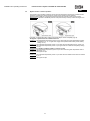
4.1
Kreuzgegenstrom-Wärmetauscher
Beide oberen Schnapphaken des Frontdeckels öffnen und diesen abnehmen. Wärmetauscher an Auszugshilfe aus
dem Gerät ziehen (Abb.20). Zur Reinigung, die Lamellen mit einem Staubsauger absaugen.
WICHTIG
☞
Kein Wasser oder aggressiven Reiniger verwenden!
WICHTIG
☞
Beim Einbau den Wärmetauscher in die Führungsschiene einsetzen und bis zum Anschlag einschieben (Abb.21).
Auszugshilfe darf nicht auf dem Dichtprofil aufliegen! (Abb.20, Pos.1)
Abb.20
Abb.21
Auszugshilfe
Pos.1
4.2
WICHTIG
☞
Filterwechsel
Zum Wechseln der Filter, beide oberen Schnapphaken des Frontdeckels öffnen und diesen abnehmen. Die Revisionsöffnung an der Vorderseite des Kompaktgeräts erlaubt einen leichten Filterwechsel der Außen-, Abluft und Bypassfilter
(Abb. 20). Optional sind zuluft- und bypassseitig F7-Filter erhältlich (Abb.22).
Bei der Verwendung von F7-Filtern, auf die Luftrichtungspfeile auf den Filter-Etiketten achten! Die Luftrichtung
ist auf dem Geräteaufkleber ersichtlich (Abb.23).
Abb.22
Abb.23
Bypassfilter
Aufkleber
Abluftfilter
F7-Bypassfilter
F7-Zuluftfilter
Außenluftfilter
– Filter
Das KWL-Kompaktgerät ist serienmäßig außen- und abluftseitig mit Klasse G4-Filter ausgestattet (nach DIN EN
13779):
• Außenluft/Abluft:
2 St. Ersatzluftfilter Grobfilter G4
1 St. Ersatzluftfilter Feinfilter F7
2 St. Bypass-Filter G4
1 St. Bypass-Filter F7
HINWEIS
☞
ELF-KWL 270/370/4/4
ELF-KWL 270/370/7
ELF-KWL 270/370/4/4 BP
ELF-KWL 270/370/7 BP
Best.-Nr. 9613
Best.-Nr. 9614
Best.-Nr. 9617
Best.-Nr. 9618
Die Filter sind je nach Verschmutzungsgrad (Gefahr von Schimmelbildung) regelmäßig (siehe Anzeige Bedienelement Werkseinstellung alle 6 Monate) zu kontrollieren, ggf. zu reinigen. Durch einmaliges Absaugen oder
nach spätestens 1-jährigem Betrieb müssen sie aus hygienischen Gründen ausgetauscht werden.
Sollten die Filter feucht oder schimmlig sein, müssen diese sofort gewechselt werden!
10
Montage- und Betriebsvorschrift
Passivhaus-Kompaktgeräte KWL EC 270/370 W R/L
D
ACHTUNG
4.3
Kondensatablauf im Gerät
Bei Wartungsmaßnahmen sicherstellen, dass der Kugelsiphon in der Bodenwanne des Gerätes nicht verstopft ist
(Punkt 2.2). Dies kann durch Eingießen einer kleinen Menge Wasser in den Siphon überprüft werden.
Hierbei darf kein Wasser in elektrische Teile gelangen!
4.4
Zugang zum interner Klemmenkasten
Die seitliche Revisionsöffnung (Abb.24) zum internen Klemmenkasten gewährleistet den freien Zugang zu den elektronischen Bauteilen (Batterie, Sicherung oder DIP-Schaltereinstellungen (Abb.25)). Die Leistungseinheit ist komplett austauschbar! Die Revisionsöffnung befindet sich bei rechten Geräten auf der linken Außenseite, bei linken Geräten auf der
rechten Außenseite.
☞
Abb.24
Abb.25
Sicherung
DIP-Schalter
Batterie
Leistungseinheit
4.5
WICHTIG
☞
Demontage EPS-Innenkorpus mit Motoreinheit
1. Zur Demontage des EPS-Innenkorpus (mit Motor- und Wärmetauschereinheit), muss der Frontrahmen am Gehäuse
entfernt werden. Hierzu Schrauben (6x) lösen und Frontrahmen abnehmen (Abb.26 und 27).
Abb.26
ACHTUNG
☞
WICHTIG
☞
Abb.27
2. Vor Entnahme des Innenkorpus, muss der Kugelsiphon demontiert werden! Hierzu Punkt 2.2
„ Kondensatablauf “ beachten! Bei der Siphon-Demontage in umgekehrter Reihenfolge wie beschrieben vorgehen.
3. Anschl. an den Führungsschienen des Wärmetauschers den EPS-Innenkorpus aus dem Metallgehäuse ziehen
(Abb. 28). Anschlusskabel müssen dabei vorsichtig nachgezogen werden.
Nicht an den Vorderkanten des Korpus ziehen, da diese ausbrechen können!
Steckverbindungen lösen und Korpus entnehmen (Abb.29).
Abb.28
11
Abb.29
Montage- und Betriebsvorschrift
Passivhaus-Kompaktgeräte KWL EC 270/370 W R/L
D
4.6
Montage EPS-Innenkorpus mit Motoreinheit
1. Bei Montage des EPS-Innenkorpus gegensätzig zu Punkt 6.5 vorgehen. Darauf achten, dass die Anschlusskabel
sauber verlegt sind (Abb.30). Anschließend EPS-Innenkorpus gleichmäßig bis zum Anschlag in das Gehäuse einschieben (Abb.31).
Abb.30
Abb.31
2. Frontrahmen auf Gehäuse stecken (Abb.32) und mit Schrauben (6x) montieren (Abb.33)
Abb.32
Abb.33
3. Anschließend Kugelsiphon montieren! Hierzu Punkt 2.2 „ Kondensatablauf“ beachten!
4.7
4.8
Sonstiges Zubehör
KWL-BE
KWL-BEC
KWL-APG
KWL-EM
KWL-KNX
Best.-Nr. 4265
Best.-Nr. 4263
Best.-Nr. 4270
Best.-Nr. 4269
Best.-Nr. 4275
Bedienelement Schiebeschalter (unterputz) mit Betriebsanzeige
Bedienelement Komfort (unterputz) mit 3 m Anschlussleitung
Bedienelement Komfort (aufputz) mit 3 m Anschlussleitung
Erweiterungsmodul
EIB-Modul (zum Anschluss an ein Gebäudeleitsystem)
KWL-LTK
KWL-CO2
KWL-FTF
KWL-VOC
Best.-Nr. 9644
Best.-Nr. 4272
Best.-Nr. 4273
Best.-Nr. 4274
Kanalfühler für Heizregister
CO2-Fühler zur Erfassung der CO2-Konzentration in der Raumluft
Feuchte-Fühler zur Erfassung der Raumluftfeuchte
Luftqualitäts-Fühler (zur Erfassung der Mischgaskonzentration)
EHR-R 1,2/160
LFBR 160 G4
EHR-R 2,4/160
WHR 160
WHSH 1100 24V (0-10V)
WHST 300 T38
KWL-ET 270/370
Best.-Nr. 9434
Best.-Nr. 8578
Best.-Nr. 9435
Best.-Nr. 9481
Best.-Nr. 8819
Best.-Nr. 8817
Best.-Nr. 5912
Elektro-Vorheizregister 1,2 kW, Durchmesser 160 mm
Vorfilter für Vorheizregister
Nachheizung 2,4 kW, Durchmesser 160 mm
Warmwasser-Heizregister für Normrohr ø 160 mm
Temperatur-Regelsystem für Warmwasser-Heizregister
Luft-Temperatur-Regelung
Enthalpie-Wärmetauscher (zur nachträglichen Umrüstung)
Anschlussbaugruppen mit Erweiterungsmodul für externe Heizregister
– elektrisch
KWL-EM
+ EHR-R 2,4/160
+ KWL-LTK
– warmwasser
KWL-EM
+ WHSH 1100 24V (0-10V)
+ KWL-LTK
2x
+ WHR 160
WHR 160
+ WHST 300 T38
12
Montage- und Betriebsvorschrift
Passivhaus-Kompaktgeräte KWL EC 270/370 W R/L
D
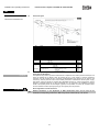
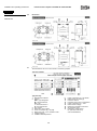
Abmessungen
Abb.34
rechte Geräteausführung
GFMBK
KGH
GLF
OGBK
JK
KWL EC 270/370 W R
\
| W{|
òMIHò
òJNOò
GII
HFL
Rückseite
òGKFò
NBK
Front
p|
JFL
Wx|
MGG
a}{~
ÈGH
HIKBK
Maße in mm
Abb.35
linke Geräteausführung
OGBK
KGH
GLF
GFMBK
JK
KWL EC 270/370 W L
p|
Wx|
GII
òJNOò
NBK
Front
W{|
JFL
MGG
\
|
Maße in mm
5.1
òMIHò
Rückseite
HFL
ABMESSUNGEN
5.0
òGKFò
KAPITEL 5
a}{~
ÈGH
HIKBK
Gerätetypenschild
Technischen Daten des KWL-Gerätes sind dem Typenschild zu entnehmen.
Typenschildbeispiel
Abb.36
q
e
r
i
d
t
o
f
y
a
g
h
k
k
w
u
s
Zeichenschlüssel:
q
w
e
r
t
y
u
i
Herstelleradresse
Ausführung:
KWL = Typenbezeichnung;
W = Wandgerät
270 = Baugröße
L = linke Geräteausführung oder
R = rechte Geräteausführung
Artikelnummer
EAN-Code/Art.-Nr.
Leistungsaufnahme [P] – Gebläse
Nennstrom [A] – Gebläse im Lüftungsbetrieb
Spannungsbereich [V]
Temperatur Arbeitsbereich
13
o
a
s
d
f
g
h
j
k
Leistungsaufnahme [P] – Vorheizung
Nennstrom [A] – Vorheizung
IP = Schutzart
Produktionscode / Herstelljahr
Leistungsaufnahme [P] – Gesamt
Nennstrom [A] – Gesamt
Hinweis auf Betriebsanleitung
QR- Produktionscode
EAN-Code/Seriennummer
für Ersatzluftfilter-Shop www.ersatzluftfilter.de
6
6
6
1
RJ12
6
1 2 3
1
1
Modbus / TCP/IP
Gatway
LAN-Router
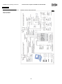
L1 N PE
3)
3) Schutzleiterstrom der 500er und 370er Type
> 3,5 mA. Externe Zuleitung mit 2 x PE oder
1 x PE > 10 mm² nach DIN EN 50178
3 x 1,5mm²
Zuleitung, 230V~
Optional:
Bauseitiger
Trennschalter /
On/off switch
DIN EN 60335-1 7.12.2
Signal der Sicherheitseinrichtung, siehe
MBV-Montage und
Betriebsvorschrift
Optional:
Bauseits bei
Raumluftabhängigen
Feuerstätten
zu erstellen !
1
1
gesteckt
offen
1)
JP-Jumper
1
Endwiderstand 120 Ohm aktiv,
letzter Teilnehmer im BUS
oder
oder
4
1
DIP
RJ10
1
max. 8 Stück
Detailplan SS-1073
Art.Nr. 4272
Sensor
KWL-CO2
2 3
DIP
4
JP
1)
4
1
4
JP
2
4
1
RJ10
4
1
RJ10
off
on
1
DIP
1
max. 8 Stück
1
4
DIP
2 3
4
1
4
1
RJ10
max. 8 Stück
Detailplan SS-1075
Art.Nr. 4274
Sensor
KWL-VOC
off
on
1)
JP
max. 2 Stück
Adressierung mit DIP beachten !
120 Ohm
Abschlusswiderstand
wenn letzter
Teilnehmer
KWL-EM, Detailplan für
- Prinzipplan Heizungsanschluss SS-1078
- Elektro-Heizung siehe SS-1069
- Warm Wasser Heizung bzw. L/SEWT siehe SS-1070
Art.Nr. 4269
Erweiterungsmodul
KWL-EM
Adressierung mit DIP beachten !
max. 8 Stück
Detailplan SS-1074
Art.Nr. 4273
Sensor
KWL-FTF
1
JP
1)
off
4
4
on
2 3
1
off
1
4
230V~
3 x 1,5mm²
Zuleitung,
1)
1
Art.Nr. 4263
KWL-BEC, Detailplan siehe SS-1072
4
RJ10
Bedienelement
KWL-BEC
KWL-SL 4/3 (3 m im Lieferumfang inkl. RJ10-Stecker)
(5 m- SL4/5, 10 m- SL4/10, 20 m- SL4/20)
on
1)
JP
Wichtige Hinweise im
Komponenten - BUS- Plan
SS-1077 und SS-1079
ohne Endwiderstand,
nicht letzter BUS-Teilnehmer
Endwiderstand
1
max. Länge siehe Tabelle SS-1077
RJ-10
Digital
+24,5 V / I max 1 A
BUS A
BUS B
GND
x
x
x
x
4
4
Bestückung der
Komponenten "beliebig".
RJ-12 RJ-10
6
4
Darstellung beispielhaft !
Analog Digital
RJ-12
Analog
+24,5 V / I max 1 A
0 - 10 V Ventilatorstufe
3,9 - 5,9 V Offset
LED rot
LED grün
GND
x
x
RJ-45
RJ-45
LAN
TX+
TXRX+
TC
RC
RXfrei
GND
8
LAN
1
2) KWL-SL 4/ 3 bis 20 bzw.
KWL EC ... easyControls
PIN
1
2
3
4
5
6
7
8
2 m, 3 x 1,5mm²
LAN-Leitung. Patch oder Crossover
Ethernet, TCP/IP, 100 Mbit/s,
- Festverlegung mit CAT7 max. 75 m und zusätzlich
Patchkabel mit min. CAT5 max. 25 m
alternativ zu KWL-BE
auch GLT-Signal 0-10 V auf
RJ-12, Pin 2: + 0-10V, Pin 6: GND möglich
max. Länge mit z.B. LiYY 6x0,34mm² = 200 m
2) KWL-SL 6/ 3 bis 20 bzw.
Helios-BUS
2) KWL-SL Leitungen bei
Unterputz Verlegung min.
in M25 Rohr verlegen.
Analog-Steuerung
KWL-SL 6/3 (3 m im Lieferumfang inkl. RJ12-Stecker)
(5 m- SL6/5, 10 m- SL6/10, 20 m- SL6/20)
85297 001 SS-1042-1045 07.04.14
Modbus
Internet
WLAN-Router
KWL-BE, Detailplan siehe SS-1071
S3
S2
S1
Art.Nr. 4265
Bedienelement
KWL-BE
1
KWLKomponenten KWL-EC ...
1
KWL-EC ...
4
14
2
1
+ -
Adresse intern Fest
Detailplan SS-1076
Art.Nr. 4275
KNX/EIB Modul
KWL-KNX
+24 V
4
3
KWL-BE
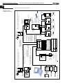
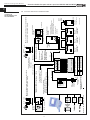
ANSCHLUSSPLAN
VERDRAHTUNGSPLAN
A
6.0
GND
KAPITEL 6
B
Montage- und Betriebsvorschrift
Passivhaus-Kompaktgeräte KWL EC 270/370 W R/L
D
Standard Anschlussplan SS-1044
Abb.37
Montage- und Betriebsvorschrift
Passivhaus-Kompaktgeräte KWL EC 270/370 W R/L
D
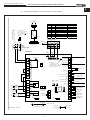
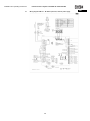
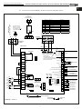
6.1
Verdrahtungsplan KWL EC... W / Basis Sonder G1, externes Netzteil
Abb.38
230 V~
Versorgung auf
der Platine
Geräte Zuleitung,
2 m 3 x 1,5 mm², 230 V~
~
Netzteil
230 V~ / 24 V=
2)
PE
RJ-45
LAN
TX+
TXRX+
TC
RC
RXfrei
GND
PIN
1
2
3
4
5
6
7
8
gn
LED 5
RJ-12
Analog
+24,5 V / I max 1 A
0 - 10 V Ventilatorstufe
3,9 - 5,9 V Offset
LED rot
LED grün
GND
x
x
RJ-10
Digital
+24,5 V / I max 1 A
BUS A
BUS B
GND
x
x
x
x
Übergabeplatine
L
-
PE
+
N
2) Schutzleiterstrom
der 370 er Type > 3,5 mA.
Externe Zuleitung mit
2 x PE oder 1 x PE > 10 mm²
nach DIN EN 50178
~
LAN
Gehäuse
Analog Digital
Schirm
24 V= SELV Einspeisung
auf der Platine
S1,
TürEndschalter
8
1
6
1
4
1
8
1
6
1
4
1
1
4
1
PE 2
LED 3
ge
(=RJ-10)
LED 4
gn
Heizung
2
N
3
N
4
4
5
5
1
RJ-45
Programmierung
1
1
8
6
RJ-12 RJ-10
Auslieferung:
JP1 Jumper gesteckt
= Endwiderstand 120 Ohm aktiv
Bei Verwendung der Klemmen
43/44/45/46 entfernen.
46
45
2 RS485-A 44
1 BUS +24 V 43
Bypass, 0-10 V 42
GND 41
Bypass, +/- 40
Digital-BUS
Hauptplatine
4
BUS-GND
3
RS485-B
6
7
7
8
8
9
9
10
10
34
33
32
bl
ws
ge
L
M1
EC
PE 3
Montageblech
bl
ws
ge
11
N
12
Relais 1
Ab-/ Fort-Luft
~
~
230 V~
Versorgung für
externes Netzteil
13
+
13
L
37
36
11
N
M2
EC
14
N
35
15
14
N
(+zu)
sw
rt
39
+ 24V= 38
GND 37
PWM, Drehzahl Zuluft 36
0-10V, Steuerung Zuluft 35
GND 34
PWM, Drehzahl Abluft 33
LED 2 LED 1 0-10V, Steuerung Abluft
32
gn
rt
BUS-GND 31
BUS +24 V 30
29
micro + 28
SD
27
Uhr-Puffer
26
auf
CR 2032, 3 V
25
24
23
F2
22
Bypass, +/-
6
frei
Relais 2
Auß-/ Zu-Luft
24 V=
Einspeisung
vom externen
Netzteil
-
F1
T4A/250V~
PE 1
Kühlkörper
F2A/250V~
PE 2
Montageblech
vom Endschalter
GehäuseSeitenwand
Seitenwand oben
85298 001 07.04.14
15
Wartungsöffnung
ws
Motor 12V+/-
(+auf)
bl
ws
ge
bl
ws
ge
Steuerung
Außen/ZuluftMotor
Steuerung
Ab/FortluftMotor
frei
sw
NTC-Fühler
Außenluft T1
NTC-Fühler
Zuluft T2
ws
NTC-Fühler
Abluft T3
NTC-Fühler
Fortluft T4
Montage- und Betriebsvorschrift
Passivhaus-Kompaktgeräte KWL EC 270/370 W R/L
D
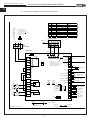
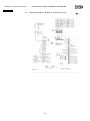
6.2
Verdrahtungsplan KWL EC... W / Basis G3, Netzteil inklusive
Geräte Zuleitung,
2 m 3 x 1,5 mm², 230 V~
Abb.39
N
2) Schutzleiterstrom
der 370 er Type > 3,5 mA.
Externe Zuleitung mit
2 x PE oder 1 x PE > 10 mm²
nach DIN EN 50178
2)
RJ-45
LAN
TX+
TXRX+
TC
RC
RXfrei
GND
PIN
1
2
3
4
5
6
7
8
PE
RJ-12
Analog
+24,5 V / I max 1 A
0 - 10 V Ventilatorstufe
3,9 - 5,9 V Offset
LED rot
LED grün
GND
x
x
RJ-10
Digital
+24,5 V / I max 1 A
BUS A
BUS B
GND
x
x
x
x
Übergabeplatine
L
LAN
Gehäuse
PE
Analog Digital
Schirm
S1,
TürEndschalter
8
1
6
1
4
1
8
1
6
1
4
1
1
4
1
PE 2
ge
F1
T4A/250V~
2
N
3
N
4
4
5
5
gn
Heizung
1
8
RJ-45
Programmierung
1
1
LED 3
(=RJ-10)
LED 4
6
RJ-12 RJ-10
Auslieferung:
JP1 Jumper gesteckt
= Endwiderstand 120 Ohm aktiv
Bei Verwendung der Klemmen
43/44/45/46 entfernen.
46
45
2 RS485-A 44
1 BUS +24 V 43
Bypass, 0-10 V 42
GND 41
Bypass, +/- 40
Digital-BUS
Hauptplatine
4
BUS-GND
3
RS485-B
6
7
7
8
8
9
9
LED 2
gn
10
10
34
33
32
bl
ws
ge
M1
EC
PE 3
Montageblech
bl
ws
ge
11
11
N
N
12
Relais 1
Ab-/ Fort-Luft
13
13
L
37
36
L
M2
EC
14
N
35
15
14
N
(+zu)
sw
rt
39
+ 24V= 38
GND 37
PWM, Drehzahl Zuluft 36
0-10V, Steuerung Zuluft 35
GND 34
PWM, Drehzahl Abluft 33
LED 1
0-10V, Steuerung Abluft 32
rt
BUS-GND 31
BUS +24 V 30
auf
29
micro
+
28
SD
27
Uhr-Puffer
26
CR 2032, 3 V
25
24
23
F2
22
Bypass, +/-
6
frei
Relais 2
Auß-/ Zu-Luft
F2A/250V~
PE 1
Kühlkörper
PE 2
Montageblech
vom Endschalter
GehäuseSeitenwand
Seitenwand oben
85298 002 07.04.14
16
Wartungsöffnung
ws
Motor 12V+/-
(+auf)
bl
ws
ge
bl
ws
ge
Steuerung
Außen/ZuluftMotor
Steuerung
Ab/FortluftMotor
frei
sw
NTC-Fühler
Außenluft T1
NTC-Fühler
Zuluft T2
ws
NTC-Fühler
Abluft T3
NTC-Fühler
Fortluft T4
Montage- und Betriebsvorschrift
Passivhaus-Kompaktgeräte KWL EC 270/370 W R/L
D
KAPITEL 7
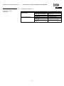
7.0
Häufige Fragen
Frage
Ursache
Behebung
1. Kondensatwasserablauf
ohne Funktion
a.) Siphon undicht
> Auf Dichtigkeit prüfen
b.) Schwimmer-Kugel im Siphongehäuse
schmutzig oder nicht vorhanden
> Schwimmer-Kugel reinigen
bzw. einlegen (Punkt 2.2)
c.) Siphon verstopft
> Siphon reinigen
d.) Gefälle nicht vorhanden
> Installation anpassen
a.) Filter verschmutzt
> Filter reinigen/wechseln
b.) Filter Zubehör (SEWT, LEWT)
verschmutzt
> Filter reinigen/wechseln
c.) Inbetriebnahme unsachgemäß
durchgeführt
> Volumenströme neu messen
HÄUFIGE FRAGEN
2. Laute Betriebsgeräusche
Notizen:
17
Alle Abbildungen ohne Gewähr!
Als Referenz am Gerät griffbereit aufbewahren!
Druckschrift-Nr.
82 204/05.14
www.heliosventilatoren.de
Service und Information
D HELIOS Ventilatoren GmbH + Co KG · Lupfenstraße 8 · 78056 VS-Schwenningen
CH HELIOS Ventilatoren AG · Steinackerstraße 36 · 8902 Urdorf
A HELIOS Ventilatoren · Postfach 854 · Siemensstraße 15 · 6023 Innsbruck
F
HELIOS Ventilateurs · Le Carré des Aviateurs · 157 avenue Charles Floquet · 93155 Le Blanc Mesnil Cedex
GB HELIOS Ventilation Systems Ltd. · 5 Crown Gate · Wyncolls Road · Severalls Industrial Park ·
Colchester · Essex · CO4 9HZ
Helios Ventilation Systems
INSTALLATION AND OPERATING INSTRUCTIONS
No. 82 204
Passive house compact unit with easyControls
KWL EC 270 W R/L
KWL EC 370 W R/L
- Heat recovery and EC technology for central ventilation
GB
ENGLISH
Helios Ventilation Systems
INSTALLATION AND OPERATING INSTRUCTIONS
Table of Contents
CHAPTER 1. GENERAL INSTALLATION AND OPERATING INSTRUCTIONS
1.0
General information
1.1
Warning and safety instructions
1.2
Important technical information
1.3
Guarantee and liability claims
1.4
Certificates - guidelines
1.5
Receipt
1.6
Storage
1.7
Shipping
1.8
Application – Operation
1.9
Mode of operation
1.10
Performance data
1.11
Fire places
1.12
Technical data
1.13
RJ connections with easyControls
1.14
Important unit components
Page 1
Page 1
Page 1
Page 1
Page 1
Page 1
Page 1
Page 1
Page 1
Page 2
Page 2
Page 2
Page 2
Page 3
Page 3
Page 4
CHAPTER 2. INSTALLATION
2.0
Assembly
2.1
Wall installation
2.2
Condensation outlet
2.3
Connecting spigots
2.4
Air ducting, ventilation circuit
2.5
Unit insulation
2.6
Electrical connection
Page 5
Page 5
Page 5
Page 6
Page 7
Page 7
Page 7
Page 7
CHAPTER 3. FUNCTIONAL DESCRIPTION
3.0
Functional layout
3.1
Initial start-up and adjustment
3.2
Bypass function “summer operation”
Page 8
Page 8
Page 8
Page 9
CHAPTER 4. SERVICE AND MAINTENANCE
4.0
Service and maintenance
4.1
Cross counter flow heat exchanger
4.2
Filter change
4.3
Condensation outlet in the unit
4.4
Access to internal terminal box
4.5
Removal of EPS inner shell
4.6
Assembly of EPS inner shell with motor unit
4.7
Other accessories
4.8
Adapter boards with extension module for external heating coil
Page 10
Page 10
Page 10
Page 10
Page 11
Page 11
Page 11
Page 12
Page 12
Page 12
CHAPTER 5. DIMENSIONS
5.0
Dimensions
Page 13
Page 13
CHAPTER 6. DIMENSIONS
6.0
Standard connection diagram SS-1044
6.1
Wiring diagram KWL EC… W
6.2
Wiring diagram KWL EC… W
Page 14
Page 14
Page 15
Page 16
CHAPTER 7. FREQUENTLY ASKED QUESTIONS
7.0
Frequently asked questions
Page 17
Page 17
This product contains batteries or accumulators. According to the German Battery Act (BattG), we are obliged to point out the following:
Batteries and accumulators must not be disposed of in household waste. You are legally obligated to return used batteries and accumulators. You can
return batteries to a community collection point or return them to the place where you bought them free of charge.
Batteries or accumulators that contain harmful substances are labelled with the symbol of a crossed-out waste bin. The chemical symbol of the
harmful substance is specified below the waste bin symbol.
Cd for Cadmium, Pb for Lead and Hg for Mercury
Please think of the environment, you can make a significant contribution to environmental protection by returning batteries and accumulators!
Installation and operating instructions
Passive house compact units KWL EC 270/370 W R/L
GB
Congratulations
You have purchased a premium product from Helios Ventilation Systems. As a Helios customer, you will benefit from the company’s many years of
experience in the sector and you have received a premium quality product. All KWL EC 270/370 W R/L units have been tested at every stage of
production. Not only has the obvious function (e.g. the fans running) been tested, but also the functions which you, as the customer, cannot test. For
example, these include internal and external leakages and electrical safety. We enable you to reduce operating costs through innovative ideas in the
field of control and feedback control systems.
However, if you unexpectedly have a problem with our unit, you can contact the specialist installer or our Helios customer service team.
1.0
CHAPTER 1
GENERAL INSTALLATION AND
OPERATING INSTRIUCTIONS
General information
To ensure safety and correct operation please, read and observe the following instructions carefully
before proceeding. All relevant national standards, safety regulations and provisions (e.g. DIN EN VDE
0100) and the technical connection conditions of the electrical supply company must be observed and
applied.
The planning office provides the planning documents necessary for the system calculation. Additional
information or a detailed plan (chargeable service) can be requested from Helios. Keep the installation
and operating instructions as a reference at the device. After the final assembly, the document must be
handed to the operator (tenant/owner).
Outline of the installation and operating instructions:
Chapters 1 – 3
General installation, operating instructions, unit installation and initial start-up and
adjustment
– intended for specialist installers
Chapters 4 – 5 Accessories + Service and Maintenance
– intended for specialist installers and end customers
All information on the operation and control of the compact unit can be found in the “easyControls” user
manual (No. 82 200), which is included in the delivery. This user manual is intended for specialist
installers and end customers.
IMPORTANT ☞
1.1
Warning and safety instructions
The accompanying symbol is a safety-relevant prominent warning symbol. All safety regulations
and/or symbols must be absolutely adhered to, so that any dangerous situation is avoided.
1.2
Important technical information
The KWL EC 270/370 W R/L has a door contact switch. If the front door is removed, the internal terminal
box is fully isolated from the power supply. In this way, normal maintenance work e.g.: checking the
condensation outlet, filter change, heat exchanger cleaning, installation of the pre-heater (accessories)
is possible.
Should the internal terminal box be opened (e.g.: fuse replacement, battery replacement), the
supply voltage must be disconnected from the power supply directly in the supply line!
The appropriate measures can be found in Chapter 2.
1.3
Guarantee and liability claims
In order to safeguard the guarantee and liability claims of the customer, the following information must
be observed:
– Implementation according to “unit” Installation and operating instructions
– Implementation according to “easyControls” operating instructions
– The use of accessories, which are not approved, recommended or offered by Helios, is not
permissible. Any damages are excluded from the guarantee.
If these instructions are not observed, all warranty claims and accommodation treatment are excluded.
This also applies to any liability claims extended to the manufacturer.
1.4
Certificates - guidelines
If the passive house compact unit is installed correctly and used to its intended purpose, it conforms to
all applicable European Standards at its date of manufacture.
1.5
Receipt
The delivery contains the unit: KWL EC 270 W R/L or KWL EC 370 W R/L
Please check delivery immediately on receipt for accuracy and damage. If damaged, please notify the
carrier immediately. In case of delayed notification, any possible claim may be void.
1.6
Storage
When storing for a prolonged time, the following steps are to be taken to avoid damaging influences:
Protection by dry, air-dustproof packing (plastic bags with drying agent and moisture indicators). The
storage place must be waterproof, vibration-free and free of temperature variations. Damages due to
improper transportation, storage or putting into operation are not liable for warranty.
1.7
Shipping
The unit is packed ex works in such a way that it is protected against normal transport strain. Carry out
the shipping carefully. It is recommended to leave the unit in the original packaging until installation to
avoid possible damages and soiling.
ATTENTION
1
Installation and operating instructions
Passive house compact units KWL EC 270/370 W R/L
GB
1.8
Application – Operation
KWL EC 270/370 W R/L compact units with heat recovery are suitable for the central ventilation of
apartments and small single-family houses, also in passive house standard (PHI). Equipped with
easyControls, the innovative control concept for simpler network connection and web browser operation.
Equipped with a highly efficient plastic cross counter flow heat exchanger.
The standard equipment permits the installation and the application in frost-free rooms > + 5 °C. If the unit
is to be used in other applications where high humidity, excessive dust, temperature in excess of 40 °C or
long periods at standstill (not running), please contact your local Helios dealer for advice. This also applies
for special technical and electrical applications.
The ventilation unit must only be used according to its intended purpose!
1.9
Mode of operation
The KWL compact unit has a plastic cross counter flow heat exchanger, in which the outside air (fresh air)
crosses the extracted building air, without coming into contact with each other. Through this procedure, the
majority of the extracted air heat is transferred to the outside air. The supply air is led by the duct system
to the primary (supply air needing) areas. The used air is extracted from the secondary areas (e.g. social
rooms, toilets, showers etc.). It flows back through the ducting to the ventilation unit, transfers the heat and
is discharged by the extract air duct into the atmosphere.
The efficiency depends on several factors. These are, among other things, the humidity of the air and the
temperature difference of the outside air and extract air. The volume flow can be regulated via the local
web server (included in the delivery). In addition, the KWL unit can also be operated via accessories. Two
control elements are available: KWL-BE and KWL-BEC.
Demand-based regulation can take place through the optional sensors KWL-VOC = air quality sensor,
KWL-CO 2 = carbon dioxide sensor or KWL-FTF = humidity and temperature sensor or through the
integrated weekly timer.
IMPORTANT ☞
The electric pre-heater EHR-R 1.2/160 (accessories, Order No. 9434) heats the outside air at very low
outside temperatures, and thus prevents the heat exchanger from freezing and guarantees its safe
function and optimum heat recovery, even in winter.
The supply air can also be heated by activating a power-regulated, external electric or hot water auxiliary
heater (accessories EHR-R... or WHR...). Another option is to cool the warmer outside air with the cooler
unit extract air.
The summer bypass is the optimum solution to conduct cooler outside air into the building during warm
periods. The air is optimally pre-filtered through the integrated filter, which ensures a hygienic unit and
simultaneously guarantees the durability of the KWL unit. A G4 filter (optional F7 pollen filter) is connected
upstream from the outside air as standard and a G4 filter is connected upstream from the extract air.
Replacement air filters can be ordered online at www.ersatzluftfilter.de
TIP!
1.10
Helios offers regular practical workshops on this topic; here you will find all the important details in a
practical environment. The dates can be found on our website www.heliosventilatoren.de under training.
Deviating versions, unfavourable installation and operating conditions can lead to the reduction of output
or an increased sound level. The figures for the air-side sound are recognised as A-weighted sound power
level LWA (corresponds to DIN 45635, T.1). The figures in A-weighted sound pressure LPA are influenced
by room and installation-specific factors. This can lead to deviations in the figures.
TIP!
IMPORTANT ☞
IMPORTANT ☞
Performance data
In order to achieve the appropriate performance data (volume flow, sound, current consumption and max.
pressure), ventilation must take place correctly (outside air/supply air and extract air/outgoing air). The
ventilation duct must be dimensioned accordingly. The filters must also be replaced regularly to maintain
optimum performance. The proper installation and adjustment of all components (units and peripheral
devices) are extremely important.
1.11
Fireplaces
The relevant applicable rules for the joint operation of fireplaces, ventilation, extraction hoods
(Federal Association of Chimney Sweeps (ZIV)) must be observed!
– General building regulation requirements
The KWL units with heat recovery can only be installed and operated in rooms with other room airdependent fireplaces if the exhaust duct is monitored by special safety devices (by client), which switch off
the KWL unit when activated. The KWL unit will be switched off until the fireplace is no longer active. In the
process, it is important to ensure that the underpressure does not exceed 4 Pa in the residential unit by
operating the KWL unit.
The KWL unit must not be operated at the same time as solid fuel fireplaces and not in residential units
with room air-dependent fireplaces, which are connected to multiple exhaust systems. Any existing
combustion air ducts and exhaust systems for solid fuel fireplaces must be capable of being shut off for
the proper operation of the ventilation system established with a ventilation unit with heat recovery.
2
Installation and operating instructions
Passive house compact units KWL EC 270/370 W R/L
GB
We recommend that you consult the responsible chimney sweep in order to accommodate your wishes
before purchasing an underpressure monitoring system for fireplaces.
TIP!
Monitoring systems are always integrated in the unit supply cable! (see circuit diagram SS-1042)
(see circuit diagram SS-1044; Position No.1)
ATTENTION
ATTENTION DANGER TO LIFE! The use of the external contact (function 1; enable/disable unit) of
the KWL-EM or the KWL-CO 2 / KWL-VOC as a shutdown method for underpressure monitoring is
not permissible.
WARNING
1.12
Technical data
KWL EC 270 D R/L
Voltage/Frequency
Rated current – ventilation
Pre-heater (outlet)
Summer bypass
Electrical power feed to UV
Air flow rates V m3/h (3 levels)
1 ~ 230 V ~/50 Hz
1.0 A
1.0 kW
Auto (adjustable)
NYM-J 3 x 1.5 mm2
285 / 170 / 110
Connection acc. to circuit diagram
Temperature operating range
Weight installation kit
Standby losses
Protection to
Installation area temperature
SS-1044
-20 °C to +40 °C
49 kg
<1W
IP20
-5 °C to +40 °C
1 ~ 230 V ~/50 Hz
2.2 A
1.0 kW
Auto (adjustable)
NYM-J 3 x 1.5 mm2
350 / 200 / 140
Connection acc. to circuit diagram
Temperature operating range
Weight installation kit
Standby losses
Protection to
Installation area temperature
SS-1044
-20 °C to +40 °C
52 kg
<1W
IP20
-5 °C to +40 °C
KWL EC 370 D R/L
Voltage/Frequency
Rated current – ventilation
Pre-heater (outlet)
Summer bypass
Electrical power feed to UV
Air flow rates V m3/h (3 levels)
1.13
TIP!
RJ connections with easyControls
Take note of the information in the “easyControls” user manual (No. 82 200).
3
Installation and operating instructions
Passive house compact units KWL EC 270/370 W R/L
GB
1.14
Important unit components
KWL EC 270/370 W Right/Left
Pos
1
2
3
4
5
6
7
8
9
10
-
Name
Filter G4 Supply air
Filter G4 Bypass
Heat exchanger
----Complete motor unit PRO
- Motor unit (KWL EC 270 W Right)
- Motor unit (KWL EC 270 W Left)
- Motor unit (KWL EC 370 W Right)
- Motor unit (KWL EC 370 W Left)
RJ adapter board
BASIC board with cooling element
Fuse type: F2AL250V – 5x20 (for 24V)
Fuse type: T4AH250V – 5x20 (for 230V)
Battery type CR2032 – 3V
---------
Fig. Right-hand version
4
Item
no.
09613
09617
84695
--------85501
85675
85676
85502
18343
82917
85737
85738
84705
---------
Pos
11
12
13
14
15
16
17
18
19
20
21
22
Name
Radial fan
- Radial fan Ø 140 (KWL EC 270)
- Radial fan Ø 160 (KWL EC 370)
------------Housing doors
- Housing door (KWL EC 270/370 W Right)
- Housing door (KWL EC 270/370 W Left)
Ball siphon
Wall mounting rails Top
Wall mounting rails Bottom
------------Condensation outlet
Item
no.
----84707
84708
----------------85514
85515
84914
84715
84716
------------82039
Installation and operating instructions
Passive house compact units KWL EC 270/370 W R/L
GB
2.0
CHAPTER 2
INSTALLATION
IMPORTANT ☞
Important note:
1. Terminal box accessible on the left side of right-hand unit versions, on the right side of left-hand
unit versions.
2. If a pre-heater or auxiliary heater is installed, the duct must be at least 1 m before and after the
heater battery from non-flammable material (see functional layout Fig.17).
3. The heater must be installed in such a way that the electric box is easily accessible.
4. In order to avoid sound transmissions, a suitable acoustic insulation must be planned on site
depending upon the structure.
5. When installing the KWL compact unit, a sufficiently accessible revision area must be provided.
6. The installation of the KWL compact unit is permitted only in frost-protected areas, since the
danger of freezing exists. The ambient temperature may not drop below +5 °C!
ATTENTION
IMPORTANT ☞
Assembly
The KWL compact unit is suitable for “hanging”, for wall installation and therefore intended for installation
within a residential/room unit. Due to the operating noise, it is recommended that the KWL unit is installed
in an ancillary room (washroom, hall, utility room, storeroom). Ensure that there is a wastewater
connection in the installation area. Please consider the information in section 2.2 "condensation outlet"!
Installation should take place in such a way to enable preferably short ventilation ducts and their troublefree connection to the unit. Tight bends can lead to increased pressure loss and flow noise.
2.1
Wall installation
In order to mount the unit to the wall, the minimum height of 300 mm up to the bottom edge of the
ventilation unit must be observed to ensure a proper condensation outlet (see Fig. below)!
1. Mount the pre-assembled mounting rails horizontally to the wall (Fig.4). Then screw down the wall rail
(in scope of delivery) to the bottom of the rear panel of the compact unit (Fig.5).
ATTENTION
2. Hang the compact unit on the mounting rail. The top mounting rail on the rear panel of the KWL unit is
pre-assembled (Fig.6).
Then screw the unit to the wall with the wall mounting rail (Fig.7).
Ensure that the unit is mounted to the wall on both wall rails!
5
Installation and operating instructions
Passive house compact units KWL EC 270/370 W R/L
GB
2.2
Condensation outlet
During the heating period, the humidity of the extract air condenses to water. In new buildings or while
having a bath or sauna as well as with laundry-drying, plenty of condensate can be formed. The
condensation must be able to run off freely from the unit. In this respect, the enclosed ball siphon (included
in delivery) must be fitted in the condensation outlet in the bottom reservoir.
– Installation of ball siphon
The ball siphon is installed in the bottom reservoir of the unit.
1. Open ball siphon, turn the mounting part a 1/4 turn (Fig.8).
2. Plug the mounting part in the condensation outlet from below, until the claw fasteners snap to the sheet
edge of the base plate (Fig.9).
3. Insert locking part and push upwards (Fig.10).
4. Then connect condensation hose DN 12 mm (not included in the delivery) to the hose connector on the
siphon housing and tighten by hand (Fig.11).
IMPORTANT
ATTENTION
☞
5. Connect siphon housing and turn the mounting part a
1/4 turn (Fig.12)
(NOTE: Ensure that the floating ball is in the housing!)
6. Connect the condensation hose DN 12 mm (length
max. 5m) to the drainage system on the housing
(siphon). In doing so, position the condensation hose
at a gradient (Fig.13). Absolutely necessary for proper
condensation outlet.
An open outlet should be installed (diagram Fig.14)
due to odour development from the dried-up siphon.
7. The ball siphon must undergo a regular cleaning
cycle.
– In order to guarantee the absence of leaks, the
ball siphon must not be subjected to lateral loads
due to the condensation hose during installation!
– The drainage pipe route must not rise behind the
siphon!
– The condensation outlet must be frost-proof!
6
Installation and operating instructions
Passive house compact units KWL EC 270/370 W R/L
GB
GB
2.3
Connecting spigots
The units are supplied with four spigots (diameter 160 mm). A secure and tight connection to the spigots
is required (e.g. Iso-Pipe IP-160), the pipe connector RVBD 160 (Order No. 9641) must be used in this
respect. The arrangement of the ventilation duct can be seen from figures 15/16, depending upon the
model.
2.4
Air ducting, ventilation circuit
When designing the ductwork, use the shortest possible runs. Airtight connections and changeovers
must be ensured for the best possible heat recovery. To avoid pressure losses, dirt build-up and noise,
use smooth ducts. The following duct diameter
- KWL EC 270 W R/L > DN 160 mm (e.g. isolated pipe system Iso-Pipe IP-160, accessories)
- KWL EC 370 W R/L > DN 160 mm (e.g. isolated pipe system Iso-Pipe IP-160, accessories)
is to be planned for main lines (outside, extract air, supply air distributor, extract collector), and the ø is
reduced accordingly for branch lines.
The supply air is led to the primary areas and the extracted air is led from the secondary areas. In order
to reduce condensation in the outside and outgoing air pipes, and any pre-heating coils and filter boxes,
these are to be insulated in an appropriate way. The minimum insulating thicknesses in accordance with
German Institute for Standardization EN in 1946-6, 05/2010 must be observed. If supply and extract air
ductwork run through unheated rooms, insulation must be provided to reduce heat losses. Fresh air
should be supplied into living rooms and bedrooms, and extraction takes place in bathrooms, toilets and
kitchens. To balance the whole system, supply and extract openings should be provided with adjustable
valves (accessories).
During extraction of polluted extract air, a filter (accessories) is to be connected. The installation of
kitchen hoods to the system (cause: dirt, fire danger, hygiene) is not permitted. To ensure air circulation
within the room, sufficient overflow openings (door gap, door grilles) are to be planned.
Fire and building regulations must be observed.
2.5
Unit insulation
If installed in heated rooms and higher humidity condensation can occur at the outside of the unit in the
outside and extract air area. In this case a water-vapour-tight insulation is to be attached laminar in this
area. Furthermore the outside and outgoing air ductwork should be insulated sufficiently.
If installed in non-heated areas (e.g. frost-protected attic) a sufficient insulation outside on the unit is to
be installed all around. Otherwise condensate formation could occur on the housing sides. The
condensate removal must be installed frost-protected, perhaps with a heater.
Furthermore, the outside air and outgoing air ducts, and any pre-heating coils and filter boxes must be
sufficiently insulated on site.
Electrical connection:
All work must be carried out with the equipment fully isolated from the power supply. The
electrical connections are to be carried out in accordance with the relevant wiring diagram and
are only to be carried out by certified electricians. All relevant national standards, safety
regulations and provisions (e.g. DIN EN VDE 0100) and the technical connection conditions of
the electrical supply company must be observed.
ATTENTION
2.6
WARNING
If the internal terminal box is opened (e.g. fuse replacement, battery replacement, etc.), then the
KWL unit must be fully isolated from the power supply!
– Allow the unit to cool down or wait for five minutes until the fans have turned off.
– Risk of electric shock, moving parts (fans) and hot surfaces.
According to DIN EN 60335-1 / VDE 0700 T1 7.12.1, a main switch and isolator (Accessories RHS 3+1
Order No. 1594) or a residual current circuit breaker model: FI 300 mA 2 Type B or B+ must be
integrated in the unit supply cable and, in this respect, the minimum requirement of a 3 mm contact
opening must be fulfilled. The main switch and isolator or the FI must be protected against being
restarted by appropriate means.
The KWL EC 270/370 W R/L models have a door contact switch and if the front door is removed, the
internal terminal box is fully isolated from the power supply. In this way, normal maintenance work
(checking the condensation outlet, filter change, heat exchanger cleaning, installation of the pre-heater
(accessories)) is possible. The owner may carry out maintenance work on the unit.
IMPORTANT NOTE
☞
Please hand the circuit diagrams to the installer!
Always use deep flush-mounted boxes for the control elements or the sensors (KWL-CO 2 , KWLVOC or KWL-FTF). The control line must always be inserted in an empty conduit M 25. It is
important to ensure that the wiring is connected in series and not radially. A deviating control
line must be installed (see circuit diagram SS-1077 or SS-1079) depending on the number of bus
components and cable lengths.
7
Installation and operating instructions
Passive house compact units KWL EC 270/370 W R/L
GB
3.0
CHAPTER 3
Functional layout
FUNCTIONAL DESCRIPTION
Pos.
T1
T2
T3
T4
T5
T6
T7
T11-T18
1
2
3
4
5
6
Alternative
3.1
NOTE
Fig. KWL EC 270/370 W Right
Name
Outside air sensor
Supply air sensor
Extracted air sensor
Outgoing air sensor
Duct sensor Type KWL-LTK (accessories)
Duct sensor Type KWL-LTK (accessories)
Frost-protection sensor Type KWL-LTK (accessories) for WW-register return
Humidity/temperature sensor: KWL-FTF
Temp-resistant or non-flammable duct (e.g. spiral duct)
Temp-resistant or non-flammable insulation
Iso-Pipe duct Ø 160
Pre-heater type: EHR-R 1.2/160
+ KWL EM
+ KWL LTK
Air filter box type: LFBR 160 G4
Electric auxiliary heater Type EHR-R 2.4/160
+ KWL EM
+ KWL LTK
Hot water auxiliary heater Type: WHR 160
and hydraulic unit
+ WHSH 1100 24V (0-10V)
+ KWL EM
+ 2x KWL LTK (T6+T7)
Item No.
----------------09644
09644
09644
04273
--------09434
04269
09644
08578
09435
04269
09644
09481
08819
04269
09644
Initial start-up and adjustment
Useful hint for adjustment!
The adjustment by means of pressure measurement is explained in the Helios practical workshops, and
this is the easiest way to adjust a KWL EC 270/370 W R/L. In this respect, a pressure measuring
connector must be mounted to each connecting socket/ventilation pipe (approx. 20 cm past the unit
connection), and the pressure hoses must be readily accessible. To balance the whole system, supply
and extract openings should be provided with adjustable elements or valves (accessories). During
extraction of polluted extract air, a filter (accessories) is to be connected. The installation of kitchen
hoods to the system (cause: dirt, fire danger, hygiene) is not permitted. To ensure air circulation within
the room sufficient overflow openings (door gap, door grilles) are to be planned.
☞
All fire regulations must be observed!
ATTENTION
TIP!
Detailed information on the adjustment of KWL wall-mounted units can be found in the
Installation and Operating Instructions “KWL easyControls Initial start-up”; No. 82 237!
8
Installation and operating instructions
Passive house compact units KWL EC 270/370 W R/L
GB
3.2
Bypass function “summer operation”
The bypass function enables a reduction of the supply air temperature and ensures a pleasant indoor
climate by bypassing the heat exchanger by means of two opposing bypass dampers.
Bypass closed: Outside air is led through a heat exchanger into the room (heat recovery active)
Bypass open: Outside air is led directly into the room (heat recovery inactive), indirect cooling of room
air
– Functional description Bypass:
If the KWL is supplied with mains voltage, the bypass damper closes completely (Fig.18).
The bypass is opened when all conditions are met:
Condition 1: The extracted air temperature (sensor T3) is higher than the bypass temperature (bypass
temperature min. +3 °C higher than supply air temperature see auxiliary heater, factory
setting +23 °C).
Condition 2: The outside air temperature (sensor T1) is lower than the extracted air temp. (sensor T3)
Condition 3: The outside air temperature (sensor T1) is higher than the outside air limit (factory setting
+15 °C)
The bypass is closed if conditions 4 and 5 or 6 and 7 are met.
Condition 4: The extracted air temperature (sensor T3) is lower than the bypass temperature which is
reduced by -2 °C.
Condition 5: The bypass is open
or
Condition 6: The outside air temperature (sensor T1) is lower than the outside air limit which is reduced
by -2 °C.
Condition 7: The bypass is open
9
Installation and operating instructions
Passive house compact units KWL EC 270/370 W R/L
GB
4.0
CHAPTER 4
Service and maintenance
SERVICE AND MAINTENANCE
All work must be carried out with the equipment fully isolated from the power supply. Risk of
electric shock, moving parts (fans) and hot surfaces.
WARNING
4.1
Cross counter flow heat exchanger
Open and remove both upper snap-in hooks on the front cover. Remove the heat exchanger from the
unit using the removal tool (Fig.20). For cleaning, vacuum the fans with a vacuum cleaner.
IMPORTANT
☞
Do not use water or aggressive cleaning products!
IMPORTANT
☞
When installing, insert the heat exchanger into the guide rails and slide in up to the stop (Fig. 21). The
removal tool must not cover the sealing element! (Fig.20, Pos.1)
4.2
IMPORTANT
☞
Filter change
In order to change the filters, open and remove both upper snap-in hooks on front cover. The inspection
opening on the front of the compact unit enables easy filter replacement of the outside air, extracted air
and bypass filter (Fig. 20). F7 filters are optional on the supply air and bypass-side (Fig.22).
When using F7 filters, pay attention on air flow direction arrows on the filter labels! The air flow
direction is shown on the unit label (Fig. 23).
– Filter
The KWL compact unit is equipped with outside and extract air filter class G4 as standard (to DIN EN
13779):
Outside air/extract air:
2 units Spare filter Course G4
ELF-KWL 270/370/4/4
Order No. 9613
1 unit Spare filter Fine
F7
ELF-KWL 270/370/7
Order No. 9614
2 units Bypass filter G4
ELF-KWL 270/370/4/4 BP
Order No. 9617
1 unit Bypass filter F7
ELF-KWL 270/370/7 BP
Order No. 9618
NOTE
☞
The filters are to be checked regularly (see controller display, factory setting every 6 months)
depending on the degree of pollution (risk of mould formation), to be cleaned if necessary. By
vacuuming once or after a maximum of 1-year operation they must be replaced for hygienic
reasons.
If the filters should be moist or mouldy, they must be changed immediately!
10
Installation and operating instructions
Passive house compact units KWL EC 270/370 W R/L
GB
ATTENTION
4.3
Condensation outlet in the unit
In connection with maintenance, make sure that the condensation outlet in the bottom reservoir is not
clogged (section 2.2). You may check it by pouring a little water into the reservoir.
Do not let water flow into electrical parts!
4.4
Access to internal terminal box
The side inspection opening (Fig.24) for the internal terminal box guarantees free access to the
electronic components (battery, fuse or DIP switch settings (Fig.25)). The power unit is completely
interchangeable! The inspection opening is located on the outer left side on right-hand units, on the
outer right side on left-hand units.
4.5
Removal of the EPS inner shell with motor unit
1. In order to remove the EPS inner shell (with motor and heat exchanger unit), the front frame on the
housing must be removed. For this purpose, loosen screws (6x) and remove front frame (Fig.26 and 27).
☞
IMPORTANT
☞
ATTENTION
☞
IMPORTANT
☞
2. Before removing the inner shell, the ball siphon must be dismantled! In this respect, observe
point 2.2 “Condensation outlet”! When dismantling the siphon, proceed as described in reverse order.
3. Using the heat exchanger guide rails, remove the EPS inner shell from the metal housing (Fig. 28).
Care must be taken when pulling the connection cables.
Do not pull on the front edges of the shell, as these can break!
Disconnect connectors and remove shell (Fig.29).
11
Installation and operating instructions
Passive house compact units KWL EC 270/370 W R/L
GB
4.6
Assembly of EPS inner shell with motor unit
1. When assembling the EPS inner shell, proceed in opposite order in comparison to point 6.5. Ensure
that the connection cables are laid accurately (Fig.30). Then push the EPS inner shell evenly up to the
stop in the housing (Fig.31).
2. Stick front frames to housing (Fig.32) and mount with screws (6x) (Fig.33)
3. Then mount ball siphon! In this respect, observe point 2.2 „Condensation outlet“!
4.7
4.8
Other accessories
KWL-BE
KWL-BEC
KWL-APG
KWL-EM
KWL-KNX
Order No. 4265
Order No. 4263
Order No. 4270
Order No. 4269
Order No. 4275
Control element Slide switch (flush-mounted) with operation display
Control element Comfort (flush-mounted) with 3 m connecting line
Control element Comfort (surface-mounted) with 3 m connecting line
Extension module
EIB Module (for connection to a building control system)
KWL-LTK
KWL-CO2
KWL-FTF
KWL-VOC
Order No. 9644
Order No. 4272
Order No. 4273
Order No. 4274
Duct sensor for heating coil
CO 2 sensor to detect the CO 2 concentration in the room air
Humidity sensor to detect the room air humidity
Air quality sensor (to detect the mixed gas concentration)
EHR-R 1.2/160
LFBR 160 G4
EHR-R 2.4/160
WHR 160
WHSH 1100 24V (0-10V)
WHST 300 T38
KWL-ET 270/370
Order No. 9434
Order No. 8578
Order No. 9435
Order No. 9481
Order No. 8819
Order No. 8817
Order No. 5912
Electric pre-heater 1.2 kW, diameter 160 mm
Pre-filter for pre-heating coil
Auxiliary heater 2,4 kW, diameter 160 mm
Hot water heating coil for standard pipe ø 160 mm
Temperature regulation system for hot water heating coil
Air temperature regulation
Enthalpy heat exchanger (for subsequent conversion)
Adapter boards with extension module for external heating coil
– electrical
KWL-EM
+ EHR-R 2.4/160
+ KWL-LTK
– hot water
KWL-EM
+ WHSH 1100 24V (0-10V)
+ KWL-LTK
] 2x
+ WHR 160
WHR 160
+ WHST 300 T38
12
Passive house compact units KWL EC 270/370 W R/L
Installation and operating instructions
GB
CHAPTER 5
5.0
Dimensions
5.1
Motor type plate
Technical data for the motor can be found on the motor type plate.
DIMENSIONS
Type plate example
Type plate key:
1
2
3
4
5
6
7
8
Manufacturer's address
Version:
KWL = type designation
W = wall-mounted unit
270 = size
L = left-hand version or
R = right-hand version
Item number
EAN-Code + Item number
Power consumption [P] – fan [kW]
Rated current [A] – fan in ventilation mode
Voltage range [V]
Installation area temperature
13
9
10
11
12
13
14
15
16
17
Power consumption [P] – Pre-heater
Rated current pre-heater [A]
Protection class IP
Production code / year of manufacture
Power consumption [P] – Total
Rated current Total [A]
Reference to operating instructions
QR production code
EAN-Code + serial number
for replacement filter shop
www.ersatzluftfilter.de
Installation and operating instructions
Passive house compact units KWL EC 270/370 W R/L
GB
CHAPTER 6
6.0
Standard connection diagram SS-1044
CIRCUIT DIAGRAM
WIRING DIAGRAM
14
Installation and operating instructions
Passive house compact units KWL EC 270/370 W R/L
GB
6.1
Wiring diagram KWL EC... W / Basis Special G1, external power supply
15
Installation and operating instructions
Passive house compact units KWL EC 270/370 W R/L
GB
6.2
Wiring diagram KWL EC... W / Basis G3, includes power supply
16
Installation and operating instructions
Passive house compact units KWL EC 270/370 W R/L
GB
CHAPTER 7
FREQUENTLY ASKED
QUESTIONS
7.0
Frequently asked questions
Question
1. Condensation outlet
not functioning
Reason
a.) Siphon leaking
b.) Floating ball in the siphon
housing dirty or non-existent
c.) Siphon clogged
d.) No gradient
a.) Filter dirty
b.) Filter accessories (SEWT,
LEWT) dirty
c.) Commissioning performed
incorrectly
2. Loud operating noise
17
Remedial action
> Check for tightness
> Clean or insert floating ball
(section 2.2)
> Clean siphon
> Adjust installation
> Clean/replace filter
> Clean/replace filter
> Re-measure volume flows
All illustrations subject to correction!
Keep at hand for future reference! Print No. 82 204/05.14
Service and Information
D HELIOS Ventilatoren GmbH & Co · Lupfenstraße 8 · 78056 VS-Schwenningen
CH HELIOS Ventilatoren AG · Steinackerstraße 36 · 8902 Urdorf / Zürich
A HELIOS Ventilatoren · Postfach 854 · Siemensstraße 15 · 6023 Innsbruck
www.heliosventilatoren.de
F HELIOS Ventilateurs · Le Carré des Aviateurs · 157 avenue Charles Floquet · 93155 Le Blanc Mesnil Cedex
GB HELIOS Ventilation Systems Ltd. · 5 Crown Gate · Wyncolls Road · Severalls Industrial Park
Colchester · Essex · CO4 9HZ·
Helios Ventilateurs
NOTICE DE MONTAGE ET D’UTILISATION
NR. 82 204 F
Groupes VMC double flux pour maisons passives
et basse consommation équipés de la régulation
easyControls
KWL EC 270 W R/L
KWL EC 370 W R/L
- Ventilation double flux centralisée avec
récupération de chaleur et moteurs EC.
FRANÇAIS
Helios Ventilateurs
NOTICE DE MONTAGE ET D’UTILISATION
Sommaire
CHAPITRE 1. INFORMATIONS GÉNÉRALES . . . . . . . . . . . . . . . . . . . . . . . . . . . . . . . . . . . . . . . . . . . . . . . . . . . .Page 1
1.0 Informations importantes . . . . . . . . . . . . . . . . . . . . . . . . . . . . . . . . . . . . . . . . . . . . . . . . . . . . . . . . . . . . . . . .Page 1
1.1 Précautions et consignes de sécurité . . . . . . . . . . . . . . . . . . . . . . . . . . . . . . . . . . . . . . . . . . . . . . . . . . . . . .Page 1
1.2 Informations techniques importantes . . . . . . . . . . . . . . . . . . . . . . . . . . . . . . . . . . . . . . . . . . . . . . . . . . . . . . .Page 1
1.3 Garantie - Réserves du constructeur . . . . . . . . . . . . . . . . . . . . . . . . . . . . . . . . . . . . . . . . . . . . . . . . . . . . . . .Page 1
1.4 Réglementations – Normes . . . . . . . . . . . . . . . . . . . . . . . . . . . . . . . . . . . . . . . . . . . . . . . . . . . . . . . . . . . . . .Page 1
1.5 Réception de l’envoi . . . . . . . . . . . . . . . . . . . . . . . . . . . . . . . . . . . . . . . . . . . . . . . . . . . . . . . . . . . . . . . . . . .Page 1
1.6 Stockage . . . . . . . . . . . . . . . . . . . . . . . . . . . . . . . . . . . . . . . . . . . . . . . . . . . . . . . . . . . . . . . . . . . . . . . . . . . .Page 1
1.7 Transport . . . . . . . . . . . . . . . . . . . . . . . . . . . . . . . . . . . . . . . . . . . . . . . . . . . . . . . . . . . . . . . . . . . . . . . . . . . .Page 1
1.8 Domaines d’utilisation . . . . . . . . . . . . . . . . . . . . . . . . . . . . . . . . . . . . . . . . . . . . . . . . . . . . . . . . . . . . . . . . . .Page 2
1.9 Fonctionnement . . . . . . . . . . . . . . . . . . . . . . . . . . . . . . . . . . . . . . . . . . . . . . . . . . . . . . . . . . . . . . . . . . . . . .Page 2
1.10 Performances . . . . . . . . . . . . . . . . . . . . . . . . . . . . . . . . . . . . . . . . . . . . . . . . . . . . . . . . . . . . . . . . . . . . . . . .Page 2
1.11 Foyers atmosphériques . . . . . . . . . . . . . . . . . . . . . . . . . . . . . . . . . . . . . . . . . . . . . . . . . . . . . . . . . . . . . . . . .Page 2
1.12 Caractéristiques techniques . . . . . . . . . . . . . . . . . . . . . . . . . . . . . . . . . . . . . . . . . . . . . . . . . . . . . . . . . . . . .Page 3
1.13 Connecteurs RJ avec easyControls . . . . . . . . . . . . . . . . . . . . . . . . . . . . . . . . . . . . . . . . . . . . . . . . . . . . . . . .Page 3
1.14 Nomenclature importante . . . . . . . . . . . . . . . . . . . . . . . . . . . . . . . . . . . . . . . . . . . . . . . . . . . . . . . . . . . . . . .Page 4
CHAPITRE 2. MONTAGE . . . . . . . . . . . . . . . . . . . . . . . . . . . . . . . . . . . . . . . . . . . . . . . . . . . . . . . . . . . . . . . . . . . .Page 5
2.0 Installation . . . . . . . . . . . . . . . . . . . . . . . . . . . . . . . . . . . . . . . . . . . . . . . . . . . . . . . . . . . . . . . . . . . . . . . . . . .Page 5
2.1 Montage mural . . . . . . . . . . . . . . . . . . . . . . . . . . . . . . . . . . . . . . . . . . . . . . . . . . . . . . . . . . . . . . . . . . . . . . .Page 5
2.2 Évacuation des condensats . . . . . . . . . . . . . . . . . . . . . . . . . . . . . . . . . . . . . . . . . . . . . . . . . . . . . . . . . . . . . .Page 6
2.3 Raccordement des conduits . . . . . . . . . . . . . . . . . . . . . . . . . . . . . . . . . . . . . . . . . . . . . . . . . . . . . . . . . . . . .Page 7
2.4 Réseaux et débits d’air . . . . . . . . . . . . . . . . . . . . . . . . . . . . . . . . . . . . . . . . . . . . . . . . . . . . . . . . . . . . . . . . .Page 7
2.5 Isolation de l’appareil . . . . . . . . . . . . . . . . . . . . . . . . . . . . . . . . . . . . . . . . . . . . . . . . . . . . . . . . . . . . . . . . . . .Page 7
2.6 Raccordement électrique . . . . . . . . . . . . . . . . . . . . . . . . . . . . . . . . . . . . . . . . . . . . . . . . . . . . . . . . . . . . . . .Page 7
CHAPITRE 3. DESCRIPTION DES SCHÉMAS . . . . . . . . . . . . . . . . . . . . . . . . . . . . . . . . . . . . . . . . . . . . . . . . . . . .Page 8
3.0 Schéma de fonction . . . . . . . . . . . . . . . . . . . . . . . . . . . . . . . . . . . . . . . . . . . . . . . . . . . . . . . . . . . . . . . . . . .Page 8
3.1 Mise en service et paramétrage . . . . . . . . . . . . . . . . . . . . . . . . . . . . . . . . . . . . . . . . . . . . . . . . . . . . . . . . . . .Page 8
3.2 Fonction bypass « été » . . . . . . . . . . . . . . . . . . . . . . . . . . . . . . . . . . . . . . . . . . . . . . . . . . . . . . . . . . . . . . . . .Page 9
CHAPITRE 4. NETTOYAGE - ENTRETIEN . . . . . . . . . . . . . . . . . . . . . . . . . . . . . . . . . . . . . . . . . . . . . . . . . . . . . .Page 10
4.0 Nettoyage et entretien . . . . . . . . . . . . . . . . . . . . . . . . . . . . . . . . . . . . . . . . . . . . . . . . . . . . . . . . . . . . . . . . .Page 10
4.1 Échangeur de chaleur à contre courant . . . . . . . . . . . . . . . . . . . . . . . . . . . . . . . . . . . . . . . . . . . . . . . . . . . .Page 10
4.2 Remplacement des filtres . . . . . . . . . . . . . . . . . . . . . . . . . . . . . . . . . . . . . . . . . . . . . . . . . . . . . . . . . . . . . .Page 10
4.3 Écoulement des condensats dans l’appareil . . . . . . . . . . . . . . . . . . . . . . . . . . . . . . . . . . . . . . . . . . . . . . . .Page 11
4.4 Accès au boîtier de raccordement interne . . . . . . . . . . . . . . . . . . . . . . . . . . . . . . . . . . . . . . . . . . . . . . . . . .Page 11
4.5 Démontage de l’unité de ventilation . . . . . . . . . . . . . . . . . . . . . . . . . . . . . . . . . . . . . . . . . . . . . . . . . . . . . . .Page 11
4.6 Montage de l’unité de ventilation . . . . . . . . . . . . . . . . . . . . . . . . . . . . . . . . . . . . . . . . . . . . . . . . . . . . . . . . .Page 12
4.7 Accessoires divers . . . . . . . . . . . . . . . . . . . . . . . . . . . . . . . . . . . . . . . . . . . . . . . . . . . . . . . . . . . . . . . . . . . .Page 12
4.8 Connexions possibles avec modules d’extensions pour batterie chaude . . . . . . . . . . . . . . . . . . . . . . . . . . .Page 12
CHAPITRE 5. DIMENSIONS . . . . . . . . . . . . . . . . . . . . . . . . . . . . . . . . . . . . . . . . . . . . . . . . . . . . . . . . . . . . . . . . .Page 13
5.0 Dimensions . . . . . . . . . . . . . . . . . . . . . . . . . . . . . . . . . . . . . . . . . . . . . . . . . . . . . . . . . . . . . . . . . . . . . . . . .Page 13
5.1 Plaque signalétique . . . . . . . . . . . . . . . . . . . . . . . . . . . . . . . . . . . . . . . . . . . . . . . . . . . . . . . . . . . . . . . . . . .Page 13
CHAPITRE 6. SCHÉMAS DE BRANCHEMENT ET DE RACCORDEMENT . . . . . . . . . . . . . . . . . . . . . . . . . . . . .Page 14
6.0 Schéma de branchement standard SS-1044 . . . . . . . . . . . . . . . . . . . . . . . . . . . . . . . . . . . . . . . . . . . . . . . .Page 14
6.1 Schéma de raccordement KWL EC... W / Base spéciale G1, alimentation externe . . . . . . . . . . . . . . . . . . .Page 15
6.2 Schéma de raccordement KWL EC... W / Base G3, alimentation incluse . . . . . . . . . . . . . . . . . . . . . . . . . . .Page 16
CHAPITRE 7. PROBLÈMES FRÉQUENTS . . . . . . . . . . . . . . . . . . . . . . . . . . . . . . . . . . . . . . . . . . . . . . . . . . . . . .Page 17
7.0 Problèmes fréquemment rencontrés . . . . . . . . . . . . . . . . . . . . . . . . . . . . . . . . . . . . . . . . . . . . . . . . . . . . . .Page 17
Tri correct de ce produit (Appareillage électronique)
Le sigle présent sur ce produit et sur la notice de montage et d’utilisation indique, qu’en fin de vie, celui–ci ne doit pas être jeté avec les ordures ménagères classiques.
Ne mettez pas cet appareil avec les autres déchets pour ne pas nuire à l’environnement, ni à la santé publique suite à un recyclage d’ordures non contrôlées. Recycler
cet appareil pour encourager la récupération efficace des ressources. Le particulier devrait contacter le revendeur, chez lequel ce produit a été acheté, ou les autorités
compétentes, pour s’informer de la meilleure façon de recycler l’appareil
.
Les utilisateurs professionnels devraient s’adresser à leurs fournisseurs et consulter les modalités du contrat de vente.
Ce produit ne doit pas être trié avec les autres déchets industriels.
Notice de montage et d’utilisation
Centrales double flux pour maisons passives KWL EC 270/370 W R/L
F
Félicitations
Vous venez d’acquérir un produit Helios Ventilateurs. Vous avez donc opté pour un produit de qualité dont vous profiterez pendant de nombreuses années.
Toutes les centrales KWL EC 270/370 W R/L ont été testées dans leur intégralité par notre service fabrication. Ces tests ne s’arrêtent pas aux fonctionnalités
visibles de l’appareil (comme par ex. le bon fonctionnement des ventilateurs), mais concernent également les fonctions qui ne peuvent être testées par nos
clients. Nous vérifions par ex. l’étanchéité interne et externe du produit ainsi que sa protection électrique. À travers des idées innovantes en matière de
régulation et de contrôle, nous réduisons les coûts de fonctionnement. Cela passe par ex. par une gestion intelligente de la protection antigel de l’échangeur
optimisée par calcul et surveillance du rendement de celui-ci.
Si vous rencontrez un problème quelconque avec notre produit, rapprochez-vous de votre installateur ou du service après-vente.
1.0 Informations importantes
CHAPITRE 1
Il est important de bien lire et respecter l’ensemble des consignes suivantes pour le bon fonctionnement de l’appareil et
pour la sécurité des utilisateurs. Veiller à bien respecter les normes nationales, règlements de sécurité et instructions.
INFORMATIONS
GÉNÉRALES
Le bureau d'études réalise le dossier technique de l'installation de ventilation double flux. Des informations complémentaires peuvent être demandées à Helios Ventilateurs. Conserver la notice de montage et d’utilisation comme référence
à proximité de l’appareil. Une fois le montage terminé, ce document doit être remis en mains propres à l’utilisateur
(locataire/propriétaire).
Sommaire de la notice de montage et d’installation:
Chapitres 1–3 Informations générales, consignes d’utilisation, installation et mise en service de l’appareil (régulation).
> Destinés à l’installateur.
Chapitres 4–5 Accessoires + Nettoyage et entretien.
> Destinés à l’installateur et à l’utilisateur final.
Le manuel d’utilisation « easyControls » (Nr. 82 200) est livré avec la centrale et contient toutes les informations
d’utilisation et de commande. Le manuel d’utilisation est destiné à l’installateur et à l’utilisateur final.
1.1
Précautions et consignes de sécurité
Le symbole ci-contre indique une consigne de sécurité. Toutes les consignes de sécurité, ainsi que les
symboles, doivent impérativement être respectés, afin d’éviter tout danger.
IMPORTANT
☞
1.2
ATTENTION
Informations techniques importantes
Les centrales KWL EC 270/370 W R/L sont équipées d’un contacteur de porte. Si le panneau frontal est retiré,
l’alimentation du secteur se coupera au niveau de la carte électronique située dans l’appareil. L’entretien de l’appareil
comprend: la vérification de l’évacuation des condensats, le remplacement des filtres, le nettoyage de l’échangeur,
l’installation possible de la batterie de préchauffage (accessoire), etc.
En cas d’ouverture de la carte électronique (par ex.: remplacement de fusibles, de filtres), couper l’alimentation
du secteur si besoin!
Toutes les dimensions nécessaires se trouvent dans le chapitre 2.
1.3
Garantie – Réserves du constructeur
Toute demande de remplacement ou de réparation à titre gratuit sera déclinée en cas de non-respect des indications
suivantes:
– Mise en service selon la notice de montage et d’utilisation de la centrale.
– Mise en service selon le manuel d’utilisation « easyControls ».
– L’utilisation d’accessoires, non fournis, non conseillés ou non proposés par Helios Ventilateurs, est interdite.
Si ces consignes ne sont pas respectées, la garantie s’annule. Idem pour les réserves du constructeur.
1.4
Réglementation – Normes
Cet appareil est conforme aux directives CE en vigueur le jour de sa fabrication et sous réserve d’une utilisation
appropriée.
1.5
Réception de l’envoi
La livraison comprend les appareils types KWL EC 270 W R/L ou KWL EC 370 W R/L.
Dès réception, vérifier l’état et la conformité du matériel commandé. En cas d’avaries, des réserves doivent être portées
sur le bordereau du transporteur. Elles doivent être précises, significatives, complètes et confirmées par lettre
recommandée au transporteur. Attention, le non-respect de la procédure peut entraîner le rejet de la réclamation.
1.6
Stockage
Pour un stockage de longue durée et pour éviter toutes détériorations préjudiciables, se conformer à ces instructions:
protéger la centrale grâce à un emballage sec, étanche à l’air et la poussière (sac en matière synthétique contenant des
sachets déshydrateurs et un indicateur d’humidité) et stocker le matériel dans un endroit abrité de l’eau, exempt de
variation de températures et de vibrations. Les dommages dus à de mauvaises conditions de transport ou de stockage,
à une utilisation anormale sont sujets à vérification et contrôle et entraînent la suppression de la garantie Helios.
1.7
Transport
L'appareil est emballé en usine et protégé contre les dégâts de transport courants. Transporter l'appareil avec soin.
Il est préférable de laisser l'appareil dans son emballage d'origine jusqu'au montage sur site pour éviter chocs et
poussières.
1
Notice de montage et d’utilisation
Centrales double flux pour maisons passives KWL EC 270/370 W R/L
F
1.8
IMPORTANT
Domaines d’utilisation
Les groupes de ventilation double flux KWL EC 270/370 W avec récupération de chaleur sont prévus pour la
ventilation centralisée de logements individuels, avec ou sans standard passif (PHI). Ils sont équipés de série de la
régulation easyControls pour une connexion au réseau la plus simple, via navigateur Web, et, d'un échangeur à contre
courant synthétique.
L’appareil doit être installé et utilisé dans des locaux hors gel (5 °C min.). En cas d’utilisation dans des
conditions difficiles (forte hygrométrie, arrêts de longue durée, fortes poussières, incidences techniques et
électromagnétiques particulières), il convient de demander conseil et d’obtenir une autorisation du constructeur.
Toute autre utilisation n’est pas autorisée!
☞
1.9
Fonctionnement
La centrale double flux KWL EC 270/370 W R/L possède un échangeur statique à contre-courant dans lequel l'air
extérieur froid et l’air extrait chaud se croisent sans contact direct entre eux. Grâce à ce principe, la majorité des
calories de l’air extrait est transmise à l’air extérieur. L’air extérieur est amené aux pièces à vivre par un réseau de gaines
et des bouches de soufflage. L’air repris provient des WC, salle de bain et cuisine. Par un réseau de gaines, il est amené
à l’appareil puis rejeté vers l’extérieur par un réseau d’extraction.
L'efficacité thermique dépend de plusieurs facteurs qui sont par ex. l'humidité de l'air et la différence de température
entre l'air extérieur et l'air repris. Le débit d'air peut être réglé via le navigateur Web embarqué (livré d'usine). La centrale
peut également être contrôlée avec une commande à distance (accessoire). Deux commandes à distance sont
disponibles au choix: KWL-BE et KWL-BEC.
Une régulation automatique peut être réalisée avec la sonde COV, sonde de qualité d’air (type KWL-VOC, option), la
sonde de dioxyde de carbone (type KWL-CO2, option), la sonde d’hygrométrie (type KWL-FTF) ou encore avec
l’horloge hebdomadaire (types WSUP et WSUP-S, option).
La batterie de préchauffage électrique EHR-R 1,2/160 (accessoire, Réf. N° 9434) réchauffe l’air extérieur en cas de
température extérieure très basse, empêchant ainsi le givrage de l’échangeur et permettant un rendement optimal,
même en hiver. La température de l’air rejeté peut se paramétrer de 0 à 10 °C. Il est possible d’augmenter la température de soufflage grâce à une batterie externe, électrique ou à eau chaude, pilotée par la régulation de la machine
(accessoire EHR-R... ou WHR...).
Pour les saisons chaudes, le bypass été est la solution optimale pour faire pénétrer à l’intérieur du bâtiment de l’air
frais. Grâce au filtre intégré, l’air sera filtré de façon optimale, permettant de garantir à la fois une meilleure hygiène ainsi
qu’une durée de vie plus longue de l’appareil. Deux filtres G4 pour l’air extérieur et pour l’air repris sont fournis de série.
Un filtre F7 (anti-pollen) peut se monter après l’échangeur de chaleur (en option).
1.10 Performances
Un montage selon les règles de l’art ainsi qu’une aspiration et un soufflage sans entrave sont la garantie d’un bon
fonctionnement. Le réseau doit être parfaitement dimensionné et installé afin d’atteindre les performances souhaitées
(débit, acoustique, puissance absorbée, pression max.). Un changement régulier de filtre est également nécessaire
pour maintenir une performance optimale du système. Une installation dans les règles de l’art de tous les composants
(centrale et périphérie) est indispensable.
Helios propose régulièrement des ateliers pratiques complets sur ce thème. Renseignez-vous auprès de votre
!
A S T U C E correspondant Helios.
Des réalisations non-conformes et/ou des conditions d’installation et de fonctionnement défavorables peuvent
conduire à une réduction des performances ou à une augmentation du niveau sonore. Les données acoustiques sont
indiquées en puissance sonore LWA pondérée en dB(A) (conformément à la norme DIN 45 635 T.1). Les données en
pression sonore pondérée LPA dépendent des caractéristiques spécifiques de la pièce. Celles-ci influencent de façon
décisive le niveau sonore généré.
1.11 Foyers atmosphériques
L’utilisation simultanée d’une ventilation contrôlée (KWL...) et d’un appareil de chauffage à foyer atmosphérique
(chaudière à gaz, poêle à bois, cheminée à foyer ouvert ou fermé...) doit se faire dans le respect des réglementations en
vigueur. Dans les bâtiments construits selon les nouvelles réglementations thermiques, le fonctionnement d'un appareil
de chauffage à foyer atmosphérique n'est permis que si l’apport d’air pour la combustion est assuré par un système
indépendant et couplé à cet appareil; le fonctionnement simultané d'une KWL et d'un foyer atmosphérique n'est
autorisé qu'à cette condition.
IMPORTANT
☞
– Recommandations particulières
Les centrales double flux avec récupération de chaleur KWL ne peuvent être installées et fonctionner simultanément
dans des locaux avec foyers ouverts que si l’évacuation des gaz brûlés est contrôlée par un dispositif de sécurité
(fourniture client) qui coupe la ventilation pendant le fonctionnement du chauffage. La centrale KWL restera coupée tant
que le foyer atmosphérique restera actif. Par ailleurs, il faut s’assurer que lors du fonctionnement de la ventilation, la
dépression dans la pièce ne dépasse pas 4 Pa.
Les centrales double flux ne doivent pas fonctionner simultanément avec un foyer à combustible solide ni dans un
logement avec des chaudières atmosphériques dont l’extraction des fumées est raccordée sur une VMC. Pour le bon
fonctionnement d'une installation de ventilation double flux, il est indispensable de pouvoir fermer temporairement les
conduits d’évacuation des fumées et des gaz de combustion.
2
Notice de montage et d’utilisation
Centrales double flux pour maisons passives KWL EC 270/370 W R/L
F
! Demandez conseil à votre ramoneur avant l’achat d’un système de surveillance.
ASTUCE
ATTENTION
Un système de surveillance sera toujours relié au câble de la centrale (voir schéma de branchement SS-1044;
position n° 1)!
ATTENTION DANGER DE MORT! L’utilisation du contact externe (fonction 1: marche/arrêt du groupe) sur
KWL-EM ou sondes KWL-CO2 / KWL-VOC comme interrupteur pour le système de surveillance n’est pas
autorisé.
AVERTISSEMENT
1.12 Caractéristiques techniques
KWL EC 270 W R/L
Tension / Fréquence
Courant nominal A
Préchauffage (sortie) kW
Bypass été
Alimentation coffret D.S.
Débit V· m3/h (3 étages)
1~ 230 V~/50 Hz
1,0 A
1,0 kW
auto (réglable)
NYM-J 3 x 1,5 mm2
285/170/110
Schéma de branchement N°
Temp. de fonctionnement
Poids brut
Consommation en veille
Protection
Plage de température
SS-1044
-20 °C à +40 °C
49 kg
<1 W
IP20
-5 °C à +40 °C
KWL EC 370 W R/L
Tension / Fréquence
Courant nominal A
Préchauffage (sortie) kW
Bypass été
Alimentation coffret D.S.
Débit V· m3/h (3 étages)
1~ 230 V~/50 Hz
2,2 A
1,0 kW
auto (réglable)
NYM-J 3 x 1,5 mm2
350/200/140
Schéma de branchement N°
Temp. de fonctionnement
Poids brut
Consommation en veille
Protection
Plage de température
SS-1044
-20 °C à +40 °C
52 kg
<1 W
IP20
-5 °C à +40 °C
1.13 Connecteurs RJ avec easyControls
! Se reporter au manuel d’utilisateur (Nr. 82 200) « easyControls ».
Fig. 1
RJ12
Câble de commande
Steuerleitung RJ10 ( digital )
RJ10 (numérique)
RJ10
Câble de commande
Steuerleitung
RJ12 ( Analog )
RJ12
(analogique)
RJ45
TCP/IP
Verbindung
Connexion
TCP/IP
ASTUCE
3
Fig. 2
Notice de montage et d’utilisation
Centrales double flux pour maisons passives KWL EC 270/370 W R/L
F
1.14 Nomenclature importante
Fig. 3
L
GM
GN
H
G
GG
MBòNBòOBòGF
GG
K
GL
I
G
HH
GK
KWL EC 270/370 W R/L (R=droite - L=gauche)
ambò[YòHMFEIMFòmòh{y~Eb
Pos.
f
D Désignation
X{{}
\{ò]Jòp|
1G Filtre
G4 soufflage
\{ò]JòXw
2H Filtre
G4 bypass
m
{wy~{
3I Échangeur
de chaleur
CCCCC
4J ----K c
{~{òDòfhe
5 Unité de ventilation complète
© c
{~{ò>ambò[YòHMFòmòh{y~?
- pour KWL EC 270 W R Version droite
© c
{~{ò>ambò[YòHMFòmòb?
-©pour
KWL EC 270 W L Version gauche
c
{~{ò>ambò[YòIMFòmòh{y~?
-©pour
KWL EC 370 W R Version droite
c
{~{ò>ambò[YòIMFòmòb?
L -h`òWzw{Cfw{
pour KWL EC 370 W L Version gauche
XWi_YCfw{òòa~{
6M Adapteur
platine RJ
iy~{}òjPò\HWbHKFlòCòKHFò>\òHJl?
7N Platine
simple avec dissipateur thermique
iy~{}òjPòjJW^HKFlòCòKHFò>\òHIFl?
8O Fusible
type: F2AL250V - 5x20 (pour 24V)
GF Xw{{òjPòYhHFIHòCòIl
9 Fusible type: T4AH250V - 5x20 (pour 230V)
C CCCCC
10 Batterie type: CR2032 - 3V
C CCCCC
- ----- -----
Fig.: version droite R
4
N°. Réf. f
D
Pos. X{{}
Désignation
WDCdD
FOLGI
09613 GG
11 hwzw{w
Ventilateur centrifuge
FOLGM
©- pour
hwzw{w
òÂòGJFò>ambò[YòHMF?
09617
KWL EC 270 - Ø 140
NJLOK
©- pour
hwzw{w
òÂòGLFò>ambò[YòIMF?
84695
KWL EC 370 - Ø 160
CCCCC
----- GH
12 CCCCC
----CCCCC
GI CCCCC
----13 ----NKKFG
GJ CCCCC
85501 14 -----NKLMK
GK ]{~
{{
85675 15 ©Panneau
frontal
NKLML
]{~
{ò>ambò[YòHMFEIMFòmòh{y~?
85676
KWL EC 270/370 W R Version droite
NKKFH
©- pour
]{~
{ò>ambò[YòHMFEIMFòmòb?
GNIJI
85502 GL a}{~
- pour KWL EC 270/370 W L Version gauche
NHOGM
18343 GM
16 mwzx{|{}}y~{{òex{
Siphon à boule
NKMIM
82917 GN
17 mwzx{|{}}y~{{òk{
Rail support haut
NKMIN
85737 GO
18 CCCCC
Rail support bas
NJMFK
HF CCCCC
85738 19 ----CCCCC
HG CCCCC
84705 20 ----CCCCC
HH a
z{wwxw|y~wy~
----21 --------22 Tuyau d’évacuation des condensats
N°. Réf.
WDCdD
CCCCC
----NJMFM
84707
NJMFN
84708
CCCCC
----CCCCC
----CCCCC
----CCCCC
----NKKGJ
85514
NKKGK
NJOGJ
85515
NJMGK
84914
NJMGL
84715
CCCCC
84716
CCCCC
----CCCCC
----NHFIO
----82039
Notice de montage et d’utilisation
Centrales double flux pour maisons passives KWL EC 270/370 W R/L
F
2.0
CHAPITRE 2
La centrale KWL EC est conçue pour être montée en position « murale » en local technique, armoire ou directement
dans le logement. En raison des bruits de fonctionnement qui peuvent varier selon la pression du réseau, il est recommandé d'installer l'appareil dans un local technique, une buanderie ou un local réserve. Penser à raccorder l'appareil
sur une canalisation d'évacuation d'eau (voir section 2.3 « Évacuation des condensats »)!
L’emplacement doit être déterminé afin de permettre un raccordement aisé et un cheminement des gaines le plus court
possible. Des coudes et raccords étroits augmentent les pertes de charges, les turbulences et le niveau sonore. Les
gaines ne doivent en aucun cas être pincées ou aplaties. Les raccords doivent être serrés et étanches. L’appareil doit
être facilement accessible pour l’entretien et les travaux d’installation.
MONTAGE
IMPORTANT
☞
ATTENTION
Notes importantes:
1. La carte électronique est accessible côté gauche sur les versions R et côté droit sur les versions L.
2. En cas d'utilisation d'une batterie de préchauffage ou de chauffage, le conduit de ventilation doit être en
matériau incombustible sur une longueur de 1 m avant et après la batterie électrique (voir schéma fig. 17).
3. Le boîtier de raccordement de la batterie électrique doit être facilement accessible.
4. Il est recommandé de prévoir, au montage de l’appareil, un dispositif empêchant la transmission des
vibrations et du bruit.
5. Lors de l’installation des centrales compactes KWL, prévoir un accès libre pour l’entretien!
6. L’installation ne doit pas se faire dans un lieu où la température peut descendre en dessous de 5 °C!
2.1
IMPORTANT
Installation
☞
Montage mural
Lors du montage mural, il est important de respecter une hauteur minimum de 300 mm par rapport au sol pour
garantir une bonne évacuation des condensats (voir schéma ci-dessous)!
distance
au sol
%RGHQDEVWDQG
min.
100 mm
PLQGPP
600
mm min.
PLQGPP
300 mm min.
PLQGPP
1. Monter le rail de support à l’horizontal sur le mur (fig. 4). Dévisser le rail de montage (fourniture usine) sous la face
arrière de la centrale compacte (fig. 5).
Fig. 5
Fig. 4
Dévisser le rail
de montage
Rail de support
ATTENTION
2. Fixer la centrale compacte au rail de support. Le rail de support supérieur est déjà préassemblé (fig. 6).
Fixer la centrale au rail de montage sur le mur (fig. 7).
S’assurer que la centrale est montée sur les deux rails!
Fig. 6
Dessous de la centrale
Fig. 7
Mur
5
Notice de montage et d’utilisation
Centrales double flux pour maisons passives KWL EC 270/370 W R/L
F
2.2
douille de fixation
avec joint
d’étanchéité
Évacuation des condensats
Pendant la saison de chauffe, l'air extrait humide peut condenser dans l'échangeur et se transformer en eau. La
condensation peut être importante, surtout dans un bâtiment neuf ou rénové, ou, après un bain, une douche, une
lessive par exemple. L'eau condensée doit pouvoir être évacuée librement de l'appareil. Le siphon à boule (livré d’usine)
doit être monté sur le trou d’évacuation du bac de récupération.
– Montage du siphon à boule
Le montage se fait directement sur le bac de récupération de la centrale.
1. Ouvrir le siphon à boule, dévisser la douille de fixation d’un quart de tour (fig. 8).
2. Insérer la douille de fixation dans le trou d’évacuation, jusqu’à ce que les clips s’enclenchent dans le fond (fig. 9).
Fig. 9
Fig. 8
élément de
verrouillage
flotteur à boule
corps du siphon
3. Insérer l’élément de verrouillage et visser vers le haut (fig. 10).
4. Monter le tuyau des condensats DN 12 mm (fourniture client) sur le tuyau de raccordement du siphon et visser
manuellement (fig. 11).
Fig. 10
raccordement tuyau
Monter le raccordement tuyau au siphon
Fig. 11
Insérer l’élément de verrouillage
Fig. 12
Fig. 13
Insérer le siphon
1/4 de tour
Tuyau des condensats
DN 12 mm (veiller à la pente!)
IMPORTANT
ATTENTION
☞
5. Insérer le siphon et le serrer d’un 1/4 de tour (fig. 12).
(NOTE: veiller à ce que le flotteur se trouve dans le siphon!)
6. Fixer le tuyau des condensats DN 12 mm (long. max. 5 m) au système de canalisations (siphon) de la maison. Raccorder le tuyau des condensats (fig. 13) en respectant
une pente, indispensable pour une bonne évacuation.
Pour éviter les odeurs dues à un assèchement du siphon, celui-ci doit être
raccordé sur une évacuation ouverte (fig. 14).
7. Le siphon à boule doit être régulièrement entretenu (autant de fois que les filtres).
– L’évacuation du siphon à boule ne doit présenter aucune contrainte au
niveau du tuyau des condensats pour assurer une étanchéité optimale!
– Garder une pente d'écoulement après le siphon!
– Poser les conduits en zone hors gel!
6
Fig. 14
Siphon
Notice de montage et d’utilisation
Centrales double flux pour maisons passives KWL EC 270/370 W R/L
F
Raccordement des conduits
L’appareil est équipé de quatre raccords femelle (diamètre 160). Les conduits d’air (par ex. IsoPipe 160) doivent être
raccordés de façon fixe et étanche aux raccords. Insérer le manchon avec joints RVBD 160 (Réf. N° 9641). Pour
chaque type de centrale, la disposition des conduits de ventilation doit se faire selon les schémas15 et 16.
GFMBK
air extérieur
W{|
òGKFò
ATTENTION
mur
Wand
airp|
soufflé
air
repris
Wx|
Fig. 16
Front
devant
Wx|
air
repris
air extérieur
W{|
air rejeté
\
|
Réseaux et débits d’air
Privilégier de préférence des réseaux courts et sélectionner des raccords étanches. Pour éviter les nuisances sonores,
les pertes de pression et accumulations de poussières dans les gaines, utiliser des conduits lisses. Les réseaux principaux (air extérieur, air extrait, collecteurs, etc.) devront être comme suit:
– KWL EC 270 W R/L > DN 160 mm (par ex. conduit isolant IsoPipe IP-160, accessoire).
– KWL EC 370 W R/L > DN 160 mm (par ex. conduit isolant IsoPipe IP-160, accessoire).
Les réseaux secondaires peuvent être réduits.
L’air extérieur doit être amené dans les pièces d’habitation (séjour, chambre à coucher, etc.), l’air vicié est repris dans
les WC, salle de bains, cuisine, buanderie, etc. Pour éviter la condensation, isoler les gaines de prise d’air extérieur et
rejeté ainsi que sur les registres de préchauffage et les boîtes à filtres. L'épaisseur de l'isolation est précisée par la norme DIN EN 1946-6, 05/2009. Si les conduits de ventilation air soufflé et repris traversent des zones non chauffées, il
faut les isoler afin d’éviter les pertes de chaleur.
Pour permettre l’équilibrage de l’installation, il est conseillé d’équiper les entrées et sorties d’air de bouches réglables
(voir accessoires en option).
La bouche de prise d’air en cuisine doit être équipée d’un filtre. La hotte ne doit pas être raccordée sur
l’installation (problèmes de colmatage par la graisse), elle doit être sur un réseau à part, avec un ventilateur de rejet de
l’air vers l’extérieur. Pour permettre un bon brassage de l’air dans l’habitation (chambres, séjour, couloir, salle de bains,
WC, cuisine), il faut prévoir des ouvertures en conséquence (bas de porte, grilles de transfert, etc.).
Les éventuels règlements concernant la protection incendie doivent impérativement être respectés.
2.5
Isolation de l'appareil
Si l’appareil est installé dans un local chauffé ou avec une hygrométrie élevée, de la condensation peut apparaître sur
les parois de l'appareil aux zones d'air rejeté et d'air extérieur. Dans ce cas, il faut isoler localement la zone avec un
isolant pare-vapeur. Par ailleurs, il faudra isoler les conduits d'air extérieur et de rejet.
Si le groupe double flux est installé dans un local non chauffé (par ex. en combles hors gel), il faudra prévoir une
isolation permanente de l'appareil pour éviter la formation de condensation sur les parois. L'écoulement des
condensats doit être hors gel. Prévoir éventuellement une résistance antigel.
Par ailleurs, il faut isoler les conduits air extérieur et air rejeté ainsi que les éventuels batteries et filtres.
2.6
Raccordement électrique
Mettre impérativement l’appareil hors tension avant tous travaux d’entretien ou à l’ouverture du boîtier de
commande! Le branchement électrique doit être réalisé, conformément aux schémas de raccordement
ci-dessous, uniquement par un électricien qualifié. Respecter les normes correspondantes, les règlements de
sécurité (par ex. DIN VDE 0100) et les TAB des EVUs.
En cas d’ouverture des cartes électroniques internes (par ex. remplacement des fusibles, de la batterie, etc.),
déconnecter impérativement la centrale!
– Laisser refroidir la centrale 5 min et attendre l’arrêt total des ventilateurs.
– Danger de choc électrique, de coupures (ventilateur) et de brûlures.
En conformité à la norme DIN EN 60335-1 / VDE 0700 T1 7.12.1, il faut protégé le groupe par un interrupteur principal
et de sécurité (accessoire RHS 3+1 Réf. N° 1594) ou d’un disjoncteur de protection (type: FI 300 mA 2 type B ou B+
dans le cordon de branchement de l’appareil) et doit avoir une ouverture de contact de 3 mm min. L’interrupteur
principal et de sécurité du disjoncteur de protection doit être équipé d’un dispositif anti-redémarrage.
Les modèles KWL EC 270/370 W R/L possèdent un contacteur de porte. Si le panneau frontal est enlevé, l’alimentation
du secteur se coupera au niveau de la carte électronique. Ainsi, les travaux d’entretien de base (vérification de l’évacuation des condensats, remplacement des filtres, nettoyage de l’échangeur, montage du préchauffage (accessoire) sont
possibles. Le propriétaire peut effectuer la maintenance de l’équipement.
NOTE IMPORTANTE
☞
L’électricien doit remettre les schémas de branchement à l’installateur!
Toujours utiliser des boîtes d’encastrement profondes pour les sondes (KWL-CO2, KWL-COV ou KWL-FTF).
Les câbles encastrés doivent être placés dans des gaines M25. Vérifier que le câblage est en série et non en
étoile. Selon les composants BUS et la longueur du câble, le câble de liaison à utiliser peut varier (voir schémas
de branchement SS-1077 et SS-1079).
7
ò
ò
GII
òJNOò
HFL
GII
mur
Wand
Front
devant
air soufflé
p|
version
gauche
2.4
AVERTISSEMENT
Fig. 15
òGKFò
air
rejeté
\
|
HFL
version
droite
òJNOò
2.3
Notice de montage et d’utilisation
Centrales double flux pour maisons passives KWL EC 270/370 W R/L
F
3.0
CHAPITRE 3
Schéma de fonction
Fig. 17
DESCRIPTION DES
FONCTIONS
cas d'utilisation d'une batterie électrique, le conduit de ventilation doit être en matériau
En
X{òl{{z}ò{{ò^{{}{Bòòzwòh
~{òGòò
òzòwy~òz{ò^{{}{
(par ex. conduit spiralé acier) sur une longueur de 1 m avant et après la batterie.
incombustible
ò{{wx{
z}{òxDòy~òx{xw{òh
~ò{{~{ò{z{ò>DXDòmy{|w
~?
Air \
|
rejeté
Air
extérieur
WÊ{|
I
jK
K
H
G
J
jL
GBòH
G
L
H
G
jG
repris
AirWx|
>jM?
hyw|
Registre WW
mmCh{}{
Airp|
soufflé
G
jI
jJ
jH
G
òòòòòòòòòjGGCjGN
Sondes de température et d'humidité
\{y~{Ej{{w|~{
>hw{}{ò_ww
?
ambiante (montage dans le local)
Fig. WxxDòambò[YòHMFEIMFòmòb
KWL EC 270/370 W - Version gauche
Désignation
Sonde T° air extérieur
Sonde T° air soufflé
X{{}
Sonde T° air repris
WÊ{||~{
Sonde T° air rejeté
p||~{
Sonde de gaine type KWL-LTK (accessoire)
Wx||~{
Sonde de gaine type KWL-LTK (accessoire)
\
||~{
aww|~{òòj{PòambCbjaòò>px{~?
Sonde antigel type KWL-LTK (accessoire) pour le registre WW
aww|~{òòj{PòambCbjaòò>px{~?
Sonde de température/humidité KWL-FTF
\
y~|~{òòj{PòambCbjaòò>px{~?ò|òmmCh{}{òhyw|
Conduit incombustible (par ex. acier spiralé)
\{y~{Ej{{w|~{òambC\j\
Isolation incombustible (par ex. laine de verre)
j{{wx{
z}{òòxDòy~òx{xw{òh
~ò>DXDòmy{|w
~?
Conduit IsoPipe ø 160
j{{wx{
z}{òòxDòy~òx{xw{òZ
}
Préchauffage type: EHR-R 1,2/160
_
Cf{òh
~òÈGLF
+ KWL-EM
l
~{}òòòòj{Pò[^hChòGBHEGLF
+ KWL-LTK
J
òòòòòòòòòòòòòòòòòòòòòòòòòòòòòòòòòòòòAòambC[c
òòòòòòòòòòòòòòòòòòòòòòòòòòòòòòòòòòòòAòambCbja
5
Caisson filtre à air type LFBR 160 G4
b||{CX
òj{Pòb\XhòGLFò]J
K
6
Batterie de chauffage électrique type EHR-R 2,4/160
[{y~{òdwy~~{}òòòòj{Pò[^hChòHBJEGLF
+ KWL-EM
òòòòòòòòòòòòòòòòòòòòòòòòòòòòòòòòòòòòòòòòòòòòòòòòòòòòòòòòòòòòòòòòAòambC[c
+ KWL-LTK
L
òòòòòòòòòòòòòòòòòòòòòòòòòòòòòòòòòòòòòòòòòòòòòòòòòòòòòòòòòòòòòòòòAòambCbja
Batterie de chauffage à eau chaude type WHR 160
mww{òdwy~~{}òj{Pòm^hòGLF
Alternative
et unité hydraulique
+ WHSH 1100 24 V (0-10V)
W{w{ zò^zw{~{òòòòòòòòòòòòòòòòòòòòòAòm^i^òGGFFòHJlò>FCGFl?
òòòòòòòòòòòòòòòòòòòòòòòòòòòòòòòòòòòòòòòòòòòòòòòòòòòòòòòòòòòòòòòòAòambC[c
+ KWL-EM
òòòòòòòòòòòòòòòòòòòòòòòòòòòòòòòòòòòòòòòòòòòòòòòòòòòòòòòòòòòòòòòòAòHòambCbjaò>jLAjM?
+ 2x KWL-LTK (T6+T7)
Pos.
T1
T2
f
D
T3
jG
T4
jH
T5
jI
T6
jJ
jK
T7
jL
T11-T18
jM
1
jGGCjGN
2
G
3
H
4I
NOTE
ATTENTION
3.1
Réf. N°
--------WDCdD
----CCCCC
----CCCCC
09644
CCCCC
09644
CCCCC
FOLJJ
09644
FOLJJ
04273
FOLJJ
----FJHMI
----CCCCC
CCCCC
09434
04269
FOJIJ
09644
FJHLO
FOLJJ
08578
FNKMN
09435
FOJIK
04269
FJHLO
09644
FOLJJ
09481
FOJNG
08819
FNNGO
FJHLO
04269
FOLJJ
09644
Mise en service et paramétrage
Note importante pour le paramétrage!
Lors des ateliers pratiques Helios, il est expliqué comment configurer facilement la régulation de la centrale KWL EC
270/370 W R/L grâce à la mesure de pression. Des mesures de pression doivent être prises à chaque raccord/conduit
d’air (à env. 20 cm de l’appareil). Les tubes de pression doivent être accessibles.
Lors du réglage de la centrale, les entrées et sorties d’air soufflé et repris sont équipées avec des éléments réglables
(accessoire). Un filtre (accessoire) est monté de série sur l’aspiration de l’air repris/vicié. Ne pas installer de hotte sur le
système (poussières, risques d’incendie, hygiène). Afin d’assurer un bon brassage d’air, prévoir des ouvertures (bas de
porte, grille de transfert) en conséquence.
Les éventuels règlements concernant la protection incendie doivent impérativement être respectés.
!
ASTUCE
Des notes détaillées concernant la régulation des centrales murales sont consultables dans la notice
d’installation et de montage « Mise en service KWL » n° 82 237!
8
Notice de montage et d’utilisation
Centrales double flux pour maisons passives KWL EC 270/370 W R/L
F
3.2
Fonction bypass « été »
La fonction bypass permet une réduction de la température de soufflage en déviant l'air de l'échangeur par un système
de double-volets opposés. Cette fonction est utilisée en été, lorsque la température extérieure est plus fraîche que la
température intérieure (par ex. la nuit) ou en cas de raccordement sur un puits canadien.
Bypass fermé: l'air extérieur traverse l'échangeur de chaleur avant d'être insufflé dans le bâtiment: la récupération de
chaleur est active.
Bypass ouvert: l'air extérieur est insufflé directement dans le bâtiment et contribue à son rafraîchissement: la récupération est inactive.
Fig. 18
Fig. 19
Clapet bypass fermé
Clapet bypass ouvert
– Fonctionnement du bypass:
Lorsque le groupe KWL est mis sous tension, le bypass se ferme complètement (fig.18).
Le bypass s’ouvre lorsque toutes les conditions suivantes sont réunies:
Condition 1: La température de l'air repris (sonde T3) est supérieure à la température de bypass réglée (Température de
bypass au moins supérieure de +3 °C à la température air soufflé, voir chauffage, réglage usine +23 °C).
Condition 2: La température de l'air extérieur (sonde T1) est inférieure à la température de l'air repris (sonde T3).
Condition 3: La température de l'air extérieur (sonde T1) est supérieure à la limitation air ext. (réglage usine +15 °C).
Le bypass se ferme lorsque les conditions 4 et 5 ou 6 et 7 suivantes sont réunies:
Condition 4: La température de l'air repris (sonde T3) est inférieure à la température de bypass réglée, réduite de -2°C.
Condition 5: Le bypass est ouvert.
OU
Condition 6: La température de l'air extérieur (sonde T1) est inférieure à la limitation air extérieur réduite de -2 °C (soit 13 °C
au réglage usine).
Condition 7: Le bypass est ouvert.
9
Notice de montage et d’utilisation
Centrales double flux pour maisons passives KWL EC 270/370 W R/L
F
4.0
CHAPITRE 4
NETTOYAGE - ENTRETIEN
AVERTISSEMENT
Nettoyage et entretien
Mettre impérativement l’appareil hors tension avant tous travaux d’entretien ou à l’ouverture du boîtier de
commande pour éviter tout risque lié au choc électrique, aux pièces tournantes et aux surfaces chaudes.
4.1
Échangeur de chaleur à contre courant
Ouvrir les deux fermetures à grenouillère placées sur le dessus du capot pour retirer la façade avant. Tirer sur le cerclage pour sortir l'échangeur (fig. 20). Nettoyer les plaques avec un aspirateur.
IMPORTANT
☞
Ne pas appliquer d’eau ou autre nettoyant!
IMPORTANT
☞
Pour le remontage, positionner l'échangeur sur les rails (fig. 21) et pousser au fond du caisson.
Le cerclage ne doit pas porter sur le joint d'étanchéité! (Fig. 20, Pos.1)
Fig. 20
Fig. 21
Cerclage
Pos.1
4.2
IMPORTANT
☞
Remplacement des filtres
Pour changer les filtres, ouvrir les deux fermetures à grenouillères en haut de la façade avant afin de retirer la porte.
L'accès aux filtres air extérieur, air soufflé et bypass (fig. 20) est direct. Des filtres de soufflage et bypass de qualité F7
sont disponibles en option (fig. 22).
Lors du changement des filtres F7, veiller à suivre les instructions de sens de l’air indiquées sur les filtres. Le
sens de l’air est indiqué sur l’étiquette de l’appareil (fig. 23).
Fig. 22
Fig. 23
Filtre bypass
Autocollant
Filtre air repris
Filtre bypass F7
Filtre air soufflé
Filtre air extérieur
– Filtre
La double flux KWL est équipée de série d’un filtre air extérieur et air repris de classe G4 (selon DIN EN 13779).
• Air extérieur/Air extrait:
2 filtres de rechange G4
1 filtre de rechange F7 (anti-pollen)
2 filtres bypass G4
1 filtre bypass F7 (anti-pollen)
NOTE
☞
ELF-KWL 270/370/4/4
ELF-KWL 270/370/7
ELF-KWL 270/370/4/4 BP
ELF-KWL 270/370/7 BP
Réf. N° 9613
Réf. N° 9614
Réf. N° 9617
Réf. N° 9618
Les filtres doivent être contrôlés et nettoyés régulièrement (risque de moisissures) en fonction de la qualité de
l’air extérieur (le témoin d’affichage entretien des filtres est pré-réglé d’usine sur une périodicité de 6 mois). Ils
peuvent être nettoyés par aspiration 1 fois mais doivent être remplacés après une année de fonctionnement
pour des raisons d'hygiène et d'efficacité.
Si les filtres sont humides ou moisis, ils doivent être impérativement remplacés dans les plus brefs délais!
10
Notice de montage et d’utilisation
Centrales double flux pour maisons passives KWL EC 270/370 W R/L
F
ATTENTION
4.3
Évacuation des condensats dans l'appareil
Lors des interventions de maintenance, vérifier que le siphon à boule du bac de récupération n’est pas bouché (voir
section 2.3). À vérifier en versant une petite quantité d’eau dans le siphon.
Veiller à ne pas verser d’eau sur les composants électriques!
La vérification et le nettoyage du système d’écoulement des condensats doivent être effectués annuellement!
4.4
Accès à la platine électronique
La trappe de visite latérale (fig. 24) permet l'accès aux composants électroniques principaux (batterie, fusible ou à
l'interrupteur DIP (fig. 25)). Cette plaque de maintenance se trouve sur le côté gauche des appareils en version droite (R)
et sur le côté droit des appareils en version gauche (L).
☞
Fig. 24
Fig. 25
Fusible
Interrupteur DIP
Batterie
Unité de puissance
4.5
IMPORTANT
☞
Démontage de l'unité de ventilation
1. Il est nécessaire de démonter le panneau frontal pour accéder à l’unité de ventilation (moteur et échangeur de
chaleur) en dévissant les 6 vis (fig. 26 et 27).
Fig. 26
ATTENTION
☞
IMPORTANT
☞
Fig. 27
2. Avant de sortir l'unité centrale, retirer le siphon à boule! Voir section 2.2.
Lire attentivement « évacuation des condensats »! Lors du démontage du siphon, suivre les étapes en sens inverse.
3. Glisser l'unité de ventilation le long des rails de supports pour la sortir de la caisse en tôle (fig. 28). Les câbles doivent
suivre le mouvement.
Ne pas tenir les coins de l'unité de ventilation au risque de les arracher!
Débrancher les connexions puis sortir l'unité de ventilation (fig. 26).
Fig. 28
11
Fig. 29
Notice de montage et d’utilisation
Centrales double flux pour maisons passives KWL EC 270/370 W R/L
F
4.6
Montage de l'unité de ventilation
1. Remontage de l'unité de ventilation en sens inverse à la section 6.5. Veiller à la bonne disposition des câbles
d'alimentation (fig. 30), puis pousser uniformément l'unité de ventilation vers le fond du caisson en tôle jusqu'en butée
(fig. 31).
Fig. 30
Fig. 31
2. Poser le panneau frontal sur la centrale (fig. 32) et fixer avec des vis (6) (fig. 33).
Fig. 32
Fig. 33
3. Pour finir, monter le siphon à boule! Se référer à la section 2.2 « Évacuation des condensats »!
4.7
4.8
Accessoires divers
KWL-BE
KWL-BEC
KWL-APG
KWL-EM
KWL-KNX
Réf. N° 4265
Réf. N° 4263
Réf. N° 4270
Réf. N° 4269
Réf. N° 4275
Commutateur à 3 positions (encastré) avec état de fonctionnement
Commande à distance (encastré) câble de 3 m de long.
Boîtier de montage (apparent) câble de 3 m de long.
Module d’extension
Module KNX/EIB (pour le raccordement du groupe KNX)
KWL-LTK
KWL-CO2
KWL-FTF
KWL-VOC
Réf. N° 9644
Réf. N° 4272
Réf. N° 4273
Réf. N° 4274
Sonde de température de gaine pour batterie de chauffe
Sonde CO2 pour mesurer le taux de concentration de CO2
Sonde d’hygrométrie pour mesurer le taux d’hygrométrie
Sonde COV pour mesurer le taux de COV
EHR-R 1,2/160
LFBR 160 G4
EHR-R 2,4/160
WHR 160
WHSH HE 24V (0-10V)
WHST 300 T38
KWL-ET 270/370
Réf. N° 9434
Réf. N° 8578
Réf. N° 9435
Réf. N° 9481
Réf. N° 8318
Réf. N° 8817
Réf. N° 5912
Batterie électrique antigel 1,2 kW, ø 160 mm
Filtre en amont de la batterie antigel
Batterie électrique 2,4 kW, ø 160 mm
Batterie eau chaude pour tube standard, ø 160 mm
Module hydraulique pour batterie eau chaude
Kit de régulation pour batterie eau chaude
Échangeur enthalpique (configurable)
Connexions possibles avec modules d’extensions pour batterie chaude
– électrique
KWL-EM
+ EHR-R 2,4/160
+ KWL-LTK
– eau chaude
KWL-EM
+ WHSH HE 24V (0-10V)
+ KWL-LTK
2x
+ WHR 160
WHR 160
+ WHST 300 T38
12
Notice de montage et d’utilisation
Centrales double flux pour maisons passives KWL EC 270/370 W R/L
F
Dimensions
KWL EC 270/370 W R
Fig. 34
air
rejeté W{|
air extérieur
\
|
GFMBK
KGH
JK
Version droite
GLF
OGBK
òMIHò
òJNOò
GII
HFL
mur
òGKFò
NBK
devant
p|
air
soufflé
JFL
Wx|
air
repris
MGG
siphon à boule
a}{~
ÈGH
HIKBK
Dim. en mm
KWL EC 270/370 W L
Fig. 35
OGBK
KGH
JK
Version gauche
GLF
GFMBK
airp|
soufflé
air
repris
Wx|
GII
òJNOò
NBK
devant
W{|
air
extérieur
JFL
MGG
\
|
air
rejeté
Dim. en mm
5.1
òMIHò
mur
HFL
DIMENSIONS
5.0
òGKFò
CHAPITRE 5
siphon
à boule
a}{~
ÈGH
HIKBK
Plaque signalétique
Les caractéristiques techniques de l’appareil sont précisées sur la plaque signalétique.
Exemple de plaque signalétique
HELIOS VENTILATOREN
78056 Villingen-Schwenningen Germany
q
Fig. 36
e
KWL EC 270 W L w
230 V 1 ~
IP 3X
u
s
TN 40°C
PC 12345
i
d
Art.-Nr. 04230-001
PFan.
0,14 kW
PPreheater 1,0 kW
PTotal
1,14 kW
t
o
f
r
0 4 2 3 0
IFan
0 0 1 .
1,02 A
IPreheater 4,35 A
ITotal
5,37 A
h
y
a
g
Einsatz und Betrieb nur gemäß Instruktions-Nr.
Operation only according to instruction no.
Utilisation uniquement selon instruction no.
1 1 0 6 1 5
85503
h
k
QR product info
www.ersatzluftfilter.de
k
Légende d’une plaque d’un ventilateur EC:
q
w
e
r
t
y
u
i
Fabricant
Désignation de l’appareil:
KWL = Nom de l’appareil;
W = Montage mural
270 = Taille
L = Version gauche de la centrale ou
R = Version droite de la centrale
Référence article
Code EAN/Réf. N°
Puissance absorbée [P] – Ventilateurs
Courant nominal [A] – Ventilateurs en marche
Plage de tension [V]
Plage de température
13
o
a
s
d
f
g
h
j
k
Puissance absorbée [P] – Préchauffage
Courant nominal [A] – Préchauffage
IP = Type de protection
Code de production / Année de fabrication
Puissance absorbée [P] – Total
Courant nominal [A] – Total
Remarque sur manuel d’instruction
QR- Code de production
Code EAN/Numéro de série
pour remplacement du filtre
6
6
6
1
RJ12
6
1 2 3
1
MODBUS/TCP/IP
passerelle
Routeur LAN
3)
3) Courant de fuite sur KWL 500 et 370 > 3,5 mA.
Prévoir 2 x câbles PE ou 1 x PE > 10 mm²
selon DIN EN 50178
3 x 1,5mm²
Alimentation, 230V~
L1 N PE
Option:
Interrupteur bipolaire
On/off switch
DIN EN 60335-1 7.12.2
(fourniture client)
Signal de commande,
voir notice d’utilisation
et de montage
Option:
À prévoir en
cas de foyer
atmosphérique
ouvert (fournit.
client) !
1
4
1
branché
ouvert
1)
JP-Jumper
résistance terminale.
laisser la résistance 120 Ohm
sur le dernier composant BUS.
enlever la résistance sur tous les
composants BUS sauf le dernier.
ou
ou
4
1
DIP
RJ10
1
8 unités max.
1
RJ10
4
4
1
Vérifier l’adressage DIP!
8 unités max.
Voir schéma SS-1074
Réf. N° 4273
1
Réf. N° 4272
2 3
DIP
4
1
4
DIP
2 3
4
1
4
1
RJ10
8 unités max.
Voir schéma SS-1075
Réf. N° 4274
Sonde
KWL-VOC
off
on
1
JP
1)
Résistance
terminale
120 Ohm
sur dernier
composant
KWL-EM, voir schéma pour:
- Schéma de principe chauffage SS-1078
- Batterie électrique voir SS-1069
- Batterie eau chaude et L/SEWT voir SS-1070
Réf. N° 4269
2 unités max.
4
2
Vérifier l’adressage DIP!
4
1
DIP
RJ10
off
on
Module d’extension
KWL-EM
8 unités max.
JP
Sonde
KWL-FTF
Voir schéma SS-1073
JP
1)
Sonde
KWL-CO2
1
JP
1)
off
4
4
on
2 3
1
off
1
4
230V~
3x1,5 mm²
Alimentation,
1)
1
Réf. N° 4263
KWL-BEC, voir schéma SS-1072
4
RJ10
Commande à distance
KWL-BEC
KWL-SL 4/3 (livré de série long. 3 m, avec fiche RJ-10)
(5 m- SL4/5, 10 m- SL4/10, 20 m- SL4/20)
on
1)
JP
Notes importantes voir
schémas composants BUS
SS-1077 et SS-1079
RJ-12 RJ-10
6
1
Disposition des
composants “au choix”.
RJ-12
RJ-10
Analogique
Numérique
+24,5 V / I max 1 A
+24,5 V / I max 1 A
0 - 10 V Vitesse ventilat.BUS A
3,9 - 5,9 V Offset
BUS B
LED rouge
GND
LED vert
x
GND
x
x
x
x
x
1
4
Config. pour exemple!
LAN Analog Numér.
RJ-45
RJ-45
LAN
TX+
TXRX+
TC
RC
RXlibre
GND
8
4
KWL-EC ...
long. max. voir tableau SS-1077
KWL EC ... easyControls
PIN
1
2
3
4
5
6
7
8
2 m, 3x1,5 mm²
Câble LAN Patch ou Crossover
Ethernet, TCP/IP, 100 Mbit/s,
- Câblage fixe CAT7 max. 75 m et
Câblage volant Patch min. CAT5 max. 25 m
Commande par signal 0-10 V possible
à la place de KWL-BE sur
RJ-12, Pin 2: + 0-10V, Pin 6: GND
1
2) KWL-SL 4/ 3 à 20.
BUS Helios
2) Poser les câbles KWL-SL
encastrés dans une gaine
M25 minimum.
Commande analogique
long. max. câble LiYY 6x0,34 mm² = 200 m
2) KWL-SL 6/ 3 à 20.
KWL-SL 6/3 (livré de série long. 3 m, avec fiche RJ-12)
(5 m- SL6/5, 10 m- SL6/10, 20 m- SL6/20)
85297 001 SS-1042-1045 07.04.14
MODBUS
Internet
1
Routeur Wi-Fi
KWL-BE, voir schéma SS-1071
S3
S2
S1
Réf. N° 4265
Commutateur
KWL-BE
1
Composants
KWL
1
KWL-EC ...
4
14
2
1
+ -
Adresse interne fixe
Voir schéma SS-1076
Réf. N° 4275
Module KNX/EIB
KWL-KNX
+24 V
4
3
KWL-BE
SCHÉMAS DE
BRANCHEMENT ET DE
RACCORDEMENT
A
6.0
B
CHAPITRE 6
GND
Notice de montage et d’utilisation
Centrales double flux pour maisons passives KWL EC 270/370 W R/L
F
Schéma de branchement standard SS-1044
Fig. 37
Notice de montage et d’utilisation
Centrales double flux pour maisons passives KWL EC 270/370 W R/L
F
6.1
Schéma de raccordement KWL EC... W / Base spéciale G1, alimentation externe
Fig. 38
230 V~
Alimentation de
la carte électronique
2) Courant de fuite
KWL 370 > 3,5 mA.
Prévoir 2 câbles PE
ou 1 câble PE > 10 mm²
selon DIN EN 50178
2)
~
Bloc d’alimentation
230 V~ / 24 V=
Alimentation,
2 m 3x1,5 mm², 230 V~
~
PE
RJ-45
LAN
TX+
TXRX+
TC
RC
RXfrei
GND
PIN
1
2
3
4
5
6
7
8
vert
LED 5
RJ-12
Analogique
+24,5 V / I max 1 A
0 - 10 V vitesse vent.
3,9 - 5,9 V Offset
LED rouge
LED verte
GND
x
x
Platine RJ
S1,
Contacteur
de porte
PE 2
LAN
Enveloppe
AnalogNumé.
blindé
24 V= Alimentation SELV
de la carte électronique
Carte-mère
8
1
6
1
4
1
8
1
6
1
4
1
LED 4
LED 3
vert
jaune
Chauffage
4
1
2
N
3
N
4
4
8
8
8
9
9
10
32
blanc
jaune
10
M1
EC
PE 3
Câble de montage
bleu
37
M2
36
jaune EC
35
N
11
11
N
12
Relais 1
Air rejeté/repris
L
14
N
15
14
N
~
~
230 V~
Alimentation vers
un bloc externe
13
13
blanc
4
1
RJ-12 RJ-10
3
RS485-B
2
RS485-A
libre
(+fermé)
noir
Moteur 12V+/-
rouge blanc
7
7
33
1
39
+ 24 V=
38
GND 37
PWM vitesse de soufflage 36
0-10 V, commande de soufflage 35
GND 34
PWM, vitesse de reprise 33
0-10 V, commande
LED 2 LED 1
32
de reprise
vert rouge
BUS-GND 31
BUS +24 V 30
29
micro + 28
SD
27
Batterie horloge 26
interne
ouvert
25
CR 2032, 3 V
24
23
F2
22
Bypass, +/-
6
6
L
6
5
5
bleu
BUS-GND 46
45
44
1 BUS +24 V 43
Standard usine:
JP1 Jumper ponté
= résistance terminale 120 Ohm Bypass, 0-10 V 42
active. À enlever en cas d’utilisation
GND 41
des bornes 43/44/45/46.
Bypass, +/- 40
1
RJ-45
Programmation
1
BUS numérique
(=RJ-10)
-
PE
+
L
N
34
RJ-10
Numérique
+24,5 V / I max 1 A
BUS A
BUS B
GND
x
x
x
x
Relais 2
Air ext./soufflage
+
24 V=
Alimentation
d’un bloc externe
-
F1
F2A/250V~
T4A/250V~
PE 1
Radiateur
PE 2
Câble de montage
vers le contacteur
Côté latéral
de l’appareil
mur latéral au-dessus
85298 001 07.04.14
15
Trappe de
visite
(+ouvert)
bleu
Commande
moteur
air ext./soufflé
jaune
blanc de
bleu
Commande
moteur
air repris/rejeté
jaune
blanc de
libre
noir
Sonde NTC
Air extérieur T1
Sonde NTC
Air soufflé T2
blanc
Sonde NTC
Air repris T3
Sonde NTC
Air rejeté T4
Notice de montage et d’utilisation
Centrales double flux pour maisons passives KWL EC 270/370 W R/L
F
6.2
Schéma de raccordement KWL EC... W / Base G3, alimentation incluse
Alimentation,
2 m 3x1,5 mm², 230 V~
Fig. 39
2) Courant de fuite sur
KWL 370 > 3,5 mA.
Prévoir 2 câbles PE ou 1 PE > 10 mm²
selon DIN EN 50178
2)
PE
LAN
Enveloppe
PE
PE 2
Carte-mère
N
3
N
4
4
36
35
blanc
jaune
11
11
N
12
14
15
1
4
1
LED 3
1
6
RJ-12 RJ-10
BUS-GND 46
45
44
1 BUS +24 V 43
Bypass, 0-10 V 42
GND 41
Bypass, +/- 40
3
RS485-B
2
RS485-A
(+fermé)
noir
39
+ 24V= 38
GND 37
PWM, vitesse de soufflage 36
0-10 V, commande de soufflage 35
GND 34
PWM, vitesse de reprise 33
LED 1
0-10 V, commande de reprise 32
rouge
BUS-GND 31
BUS +24 V 30
ouvert
29
micro
+
28
SD
27
Batterie horloge 26
interne
CR 2032, 3 V
25
24
23
F2
22
Moteur 12V+/-
blanc
Bypass, +/-
LED 2
vert
Relais 1
Air repris/rejeté
14
N
libre
rouge
13
N
1
Standard usine:
JP1 Jumper ponté
= résistance terminale 120 Ohm
active. À enlever en cas
d’utilisation des bornes
43/44/45/46.
13
L
4
RJ-45
10
L
M2
EC
1
4
10
37
6
8
9
9
PE 3
Câble de montage
bleu
1
8
8
32
8
7
7
N
1
6
6
M1
EC
4
5
5
jaune
1
Chauffage
Programmation
2
6
vert
1
1
1
jaune
T4A/250V~
bleu
AnalogNumé.
8
LED 4
F1
blanc
RJ-10
Numérique
+24,5 V / I max 1 A
BUS A
BUS B
GND
x
x
x
x
blindé
BUS numérique
(=RJ-10)
L
S1,
Contacteur
de porte
33
RJ-12
Analogique
+24,5 V / I max 1 A
0 - 10 V vitesse vent.
3,9 - 5,9 V Offset
LED rouge
LED verte
GND
x
x
Platine RJ
N
34
RJ-45
LAN
TX+
TXRX+
TC
RC
RXlibre
GND
PIN
1
2
3
4
5
6
7
8
Relais 2
Air extérieur/soufflage
F2A/250V~
PE 1
Radiateur
PE 2
Câble de montage
vers le contacteur
Côté latéral
de l’appareil
mur latéral au-dessus
85298 002 07.04.14
16
Trappe
de visite
(+ouvert)
bleu
Commande
moteur
air ext./soufflé
jaune
blanc de
bleu
Commande
moteur
air repris/rejeté
jaune
blanc de
libre
noir
Sonde NTC
Air extérieur T1
Sonde NTC
Air soufflé T2
blanc
Sonde NTC
Air repris T3
Sonde NTC
Air rejeté T4
Notice de montage et d’utilisation
Centrales double flux pour maisons passives KWL EC 270/370 W R/L
F
CHAPITRE 7
7.0
Problèmes fréquemment rencontrés
Question
Raison
Réparation
1. L’eau des condensats ne
s’écoule pas
a.) Le siphon fuit
> Tester l’imperméabilité
b.) Le flotteur dans le boîtier du siphon est
sale ou inexistant
> Nettoyer ou introduire le
flotteur (section 2.2)
c.) Le siphon est bouché
> Nettoyer le siphon
d.) La pente est inexistante
> Réajuster l’installation
a.) Le filtre est sale
> Nettoyer/changer le filtre
b.) Le filtre des accessoires (SEWT, LEWT)
sont sales
> Nettoyer/changer le filtre
c.) La mise en service a mal été faite
> Régler les débits d’air
PROBLÈMES FRÉQUENTS
2. La centrale est très bruyante
Notes:
17
Illustrations non contractuelles.
Conservez la notice à proximité de l’appareil.
N° Réf. 82204/09.14
www.helios-fr.com
Service et informations
D HELIOS Ventilatoren GmbH + Co KG · Lupfenstraße 8 · 78056 VS-Schwenningen
CH HELIOS Ventilatoren AG · Steinackerstraße 36 · 8902 Urdorf
A HELIOS Ventilatoren · Postfach 854 · Siemensstraße 15 · 6023 Innsbruck
F
HELIOS Ventilateurs · Le Carré des Aviateurs · 157 avenue Charles Floquet · 93155 Le Blanc Mesnil Cedex
GB HELIOS Ventilation Systems Ltd. · 5 Crown Gate · Wyncolls Road · Severalls Industrial Park ·
Colchester · Essex · CO4 9HZ