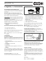
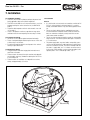
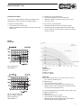
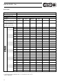
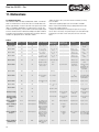
1
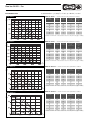
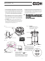
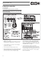
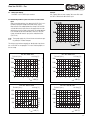
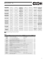
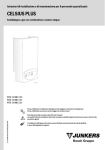
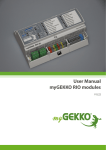
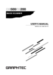
Installation and Operating Instructions No. 91527.002 Roof fan DV EC... Pro with EC-technology For Central Ventilation System ZLS Roof fan DV EC... Pro For the connection and configuration, as well as the operation of the operator terminal BDT or the software, please refer to ZLS-DVEC Quick Overview (No. 92870) for advice. 1. Foreword This manual contains instructions and information required for the safe and optimal installation of the roof fan DV EC... Pro. This manual applies for the following types: DV EC 200 Pro DV EC 250 Pro DV EC 400 A Pro DV EC 400 B Pro (Ref.No. 8385) (Ref.No. 8386) (Ref.No. 8387) (Ref.No. 8389) Read this manual carefully before commencing installation or maintenance of the fan. It is also intended as a reference work for operation and maintenance, so that this can be carried out in a sound manner. As a supplement the ELS-DVEC quick overview can be pulled up. This installation and operating instructions have been compiled with the greatest diligence by Helios. However, no rights may be derived from this publication. Helios also retains all rights to change the contents of this document without prior notification. Helios wishes you a lot of enjoyment in your DV EC..Pro roof fan. 2. Warrenty and liability 2.1 General 2.3 Liability The general sales conditions of Helios Ventilatoren apply to the DV EC..Pro roof fan. The DV EC..Pro has been designed for extraction of (polluted) air, which is diagonally exhausted. Any other application is seen as ‘inappropriate use’ and may result in damage to the device or personal injury, for which the manufacturer cannot be held liable. 2.2 Warranty claims - Exclusion of liability If the preceding instructions are not observed all warranty claims and accommodation treatments are excluded. This also applies to any liability claims extended to the manufacturer. The warrenty will be cancelled if: • • • • installation has not been carried out to the applicable regulation; the defects are due to incorrect connections, inexpert use or soiling of the fan; and repairs have been made without permission from the supplier. to be carried out on the fan may only be carried out by ☞ Work a registered/qualified installer manufacturer is not responsible for any damage derived ☞ The from: • non compliance with the safety, operating and maintenance instructions in this manual; • the use of components not supplied by the manufacturer; • normal wear and tear. On-side disassembly and assembly costs are not covered by the terms of the warrenty. If a defect occurs during the warranty period, please notify the installer. ! Illustrations and specifications without obligation. Subject to technical changes. 2 Roof fan DV EC... Pro 3. Safety / 4. Technical data Safety 4.1 General specifications It is important that you heed the safety regulations given below, for sensible use of the DV EC..Pro roof fan but also for your own safety and that of other people Fan characteristics The fan characteristics (page 4) indicate the air produced at various speeds. 3.1 General safety regulations Delivery side noise • Always comply with the safety regulations and instructions given in this manual. • Make sure that the fan and/or parts thereof, not (yet) anchored and tools cannot fall/blow off the roof or cause damage or personal injury in any other manner. • When the fan is completely or partly dismantled, make sure nobody can touch rotating parts or parts under current. • Do not leave a (partly) dismantled fan which is connected to the power supply, unattended. • Make sure that parts which conduct current do not become wet. • The fan must be fitted in such a manner that there is no risk of anybody touching the side of the fan which does not have a protective screen(see DIN EN ISO 13857). • When mounting do not allow moisture to enter the control unit. During rain or fog, the controller must be covered! The noise pressure level in dB(A) is measured on the delivery (=exhaust side) of the fan at a distance of 4 metres, horizontally, under free field conditions, unblocked suction (ref. 2 · 10-5 N/m²). As the distance to the source of noise (= fan) increase, the noise will decrease, to the extent that the noise is reduced by approx. 6 dB(A) when the distance is doubled. Suction side noise The noise production at the suction side is measured at the suction side of the fan (ref. 10-12 W). 3.2 Pictograms used The following pictogram may be used in this manual: ☞ Point of attention 3 Roof fan DV EC... Pro 4.2 Performance data at standard condition = r 1,20 kg/m3 (=^ T= 20 °C, pa = 1013 hPa) = sea level ■ DV EC 200 Pro – current and noise level, performance related DV EC 200 Pro Dpfa Pa Setting / Performance 90 % 80 % 65 % 50 % 15 % Sound power level suction side dB(A) % A W dB(A) in 4 m 100 1,38 180 52 70 90 1,15 130 50 68 80 0,90 106 47 66 65 0,57 70 42 62 50 0,31 41 35 55 30 0,13 10 24 44 15 0,09 5 22 42 ■ DV EC 250 Pro – current and noise level, performance related Setting / Performance Current consumption Power consumption Noise level Sound pressure level Sound power level suction side 100 % 90 % 80 % 65 % 50 % % A W dB(A) in 4 m dB(A) 100 1,78 412 60 75 90 1,54 354 58 73 80 1,14 264 55 70 65 0,67 154 50 66 50 0,36 78 43 61 30 0,16 24 35 49 15 0,10 11 24 43 Installation of the DV EC..Pro on a base attenuator reduces the sound power level by approx. 15 dB(A) 30 % 15 % V· m3/h ■ DV EC 400 A Pro – current and noise level, performance related DV EC 400 A Pro Setting / Performance Current consumption Power consumption Noise level Sound pressure level Sound power level suction side 100 % 90 % 80 % 65 % 30 % 15 % % A W dB(A) in 4 m dB(A) 100 1,33 303 51 68 90 1,01 232 49 66 80 0,77 176 46 64 65 0,47 103 41 61 50 0,26 53 34 54 30 0,14 18 25 54 15 0,10 9 22 42 Installation of the DV EC..Pro on a base attenuator reduces the sound power level by approx. 15 dB(A) 50 % V· m3/h ■ DV EC 400 B Pro – current and noise level, performance related DV EC 400 B Pro Dpfa Pa Noise level Sound pressure level V· m3/h DV EC 250 Pro Dpfa Pa Power consumption Installation of the DV EC..Pro on a base attenuator reduces the sound power level by approx. 15 dB(A). 30 % Dpfa Pa Current consumption 100 % Setting / Performance Current consumption Power consumption Noise level Sound pressure level Sound power level suction side 100 % 90 % % A W dB(A) in 4 m dB(A) 100 3,32 755 65 80 90 2,90 660 64 79 80 2,10 485 60 76 65 1,25 285 55 71 50 0,70 156 48 64 30 0,27 48 34 53 80 % 65 % 50 % 15 0,17 21 23 43 Installation of the DV EC..Pro on a base attenuator reduces the sound power level by approx. 15 dB(A) 30 % 15 % V· m3/h Roof fan DV EC... Pro 4.3 Exploded view with parts list 3 2 11 9 6 12 5 10 8 7 Housing 1 Fan cover 2 Air cap 3 Isolation switch 4 Motor frame 5 Controls 6 Motor-Impeller 7 Sealing rubber 8 Screw connection 9 Cable strap 10 Pull relief 11 Pressure sensor 12 1 4 5 Roof fan DV EC... Pro 4.4 Dimensioned sketches øD F E ø10(4x) B G H Vent. type DV EC 200 Pro DV EC 250 Pro DV EC 400 .. Pro 6 Diimensions in mm A B D 460 330 575 580 450 708 665 535 863 E F 60 473 60 540 60 601 G H 44 196 48 241 64 302 Roof fan DV EC... Pro 5. Regulation / 6. Communication MX 5.1 Self-regulating mechanical ventilation system The DV EC..Pro roof fan has an electronic pressure control. The pressure in the suction line under the fan is automatically regulated to a constant value. A pressure transmitter has been fitted under the cap of the DV EC..Pro for this purpose and is electrically connected as standard. The hose supplied must be connected to the ventilating system under the fan or silencer, in order to measure the pressure. It works as follows: The pressure transmitter converts the measured pressure into a 0 – 10V signal for regulation of the DV EC ..Pro. The speed of the DV EC..Pro roof fan and thereby the pressure is regulated on the basis of this 0 – 10V signal. The required constant pressure is set using the control unit or via a PC/laptop. See Cap. 6.1, 6.2 and 6.3 for details. 5.2 Manual setpoint input via potentiometer on control unit As an alternative to programming via the ZLS BDT or the ZLS IF, the potentiometer can be used on the control unit for setpoint adjustment. - In the "analog" mode, the power in% - In the "digital" mode, the pressure in Pa Further information on this topic can be found in the current Quick Overview "chapter 3, potentiometers on the control unit" the potentiometer is not set to "0", the software setting is ☞ Ifignored! MENU OK POWER CONTROL UNIT VU Method of operation The plug of the unit is inserted into DV EC..Pro connection. Once the control unit has been switched on, the current data of the DV EC..Pro is shown on the display of the unit. These settings can be changed. Consider the following applications, for example: • adjustment on side or subsequent re-adjustment of the capacity of the DV EC..Pro; • setting the required pressure; • setting an address (DV EC..Pro in network). The unit is supplied in a case with a user’s manual. Also included with the unit is a charging unit for charging in a car (12 V) or via a wall socket (230 V). Never store ZLS-BDT with empty batteries. Otherwise, the durability of the battery is extremely reduced! ☞ 6.3 Interface ZLS-IF for Laptop/PC (accessory Ref.No. 8391) The Helios Maintenance Software can be used for direct communication between a laptop/PC and the DV EC... Pro. For connecting the DVEC to a laptop/PC a RS 485/232-converter is used (accessory ZLS-IF, Ref.No. 8391). ( 6. Communication 6.1 Reading and adjustment Each DV EC..Pro is fitted with a connection for the control unit or a laptop/PC. This connection can be found under the DV EC..Pro cover. Various units can be adjusted and read via this connection, such as: • type of fan and controls; • required capacity and limitations of minimum and maximum capacity; • required pressure for day and night; • current speed; • current pressure; • address and group number (for application of DV EC..Pro in a network); • malfunctions. In case of a desired extension of the data line, the data line should not exceed a maximum length of 50 m, otherwise a release of the factory is necessary. The data line (twisted pair) must be shielded (e.g. JY [ST] Y 2 x 2 x 0,8 mm²). 6.2 Control unit ZLS-BDT (accessory Ref.No. 8390) The control unit allows for direct communication with the fan. The possibilities for adjustment and reading are virtually the same as those for the control unit. The main difference is that, when you use a laptop/PC, the DV EC..Pro settings can be saved as a file. The time response for pressure and speed can be indicated graphically and be printed out when required. An overview of possibilities is shown in the quick overview: connection / configuration. 6.4 DV EC... Pro network A network of fans can be built, by interconnecting of a number of DVEC fans using the communication connection. The serial connection of each fan is double, in order to interconnect them. Each fan in the network is programmed with its own address, via a laptop/PC or a control unit. The shielded data line (twisted pair) should not exceed a maximum length of 50 m, otherwise a release of the factory is necessary. The last device in the chain must be provided with a final resistance of 120 W. Data line(e.g.): RS A = J Y [ST] Y 2 x 2 x 0,8 mm2 RS B = J Y [ST] Y 2 x 2 x 0,8 mm2 7 Roof fan DV EC... Pro 7. Installation 7.1 Installation conditions • The DV EC..Pro must be installed according to the general and locally applicable safety and installation regulations. • The DVEC must be fitted in such a manner that there is no risk of anybody touching the suction side of the fan (see DIN EN ISO 13857). • The permissible temperature of the air to be moved is from -30 °C und +60 °C. • The fan is designed for continuous operation and may not be switched on and off more frequently than once every 5 minutes. 7.2 Transport and storage • The DV EC..Pro must be transported and stored horizontally. • The fan should preferably be lifted using the recesses in the side of the housing or on the base. • Ensure that the packing materials are disposed of in an environmentally responsible manner. 7.3 Checking the delivery • The type indication and other fan type plate information must match that on the order. • The box contains the manual, the quick overview and a bag with mounting bolts and rings, intended for attaching the DV EC..Pro to a mounting curb. • The box contains an installation set; a bag with hose column, clamps and approximately 1,5 m hose. 7.4 Installation General • It is vital that the roof construction or foundation on which the DV EC..Pro is to be installed is sufficiently rigid. If it is not rigid enough, undesirable vibrations may occur during operation of the fan. • The fan must be installed using the supplied bolts and rings. Ensure that both the foundation and the surface into which the bolts are screwed are sufficiently strong to retain the fan even under severe weather conditions. • The fan must be mounted horizontally to avoid rain and wind blowing into the fan. The maximum permissible angle of installation is 5° to the horizon. • The power supply cable, any control cables and possibly a pressure hose can be fed through a tube leading from under the base of the fan to under the fan cover. This tube is indicated under the fan cover as ‘supply cable’, see 7.1. A tube to one of the recesses in the corners in the ventilators can be used to feed cables to the operating switch. This is indicated by ‘cables’, see 7.1. Fig. 7.1 Netzzuleitung 8 Roof fan DV EC... Pro • A pressure transmitter is fitted under the fan cover and is electrically connected to the controls by means of a 3-wire connection. • An air hose is pre-fitted standard to the inner hose column on the bottom of the pressure transmitter, which is led through a tube to one of the recesses on the corners of the fan, see 7.2 and/or 7.2.1. This hose is used for measurement of the ambient pressure. • Fix the supplied hose to the outer hose column on the bottom of the pressure transmitter, see 7.2.1. Lay this air hose via one of the tubes under the cover, to the place in the unit where the pressure must be measured. The pressure is measured under the fan or the silencer. • The supplied installation set can be used for attachment of the hose. The brackets are provided for attachment of the air dose, the cable gland and the aluminium tube can be used as the pressure measuring point in the mounting curb, see 7.3. • Ensure the air hose in the pressure measuring point is always fitted outside of the air flow or close along the wall. When not installed exactly upright, not only the static pressure is measured but also a dynamic pressure, so that the regulator cannot react accurately to a constant, static pressure. mounting the DV EC... Pro a shutter must be installed ☞ inWhen the extract duct, so that no humidity condenses at standstill in the electronics of the cold fan and consequently damage can be incurred. In this case, no warrenty is given ! Fig. 7.3 Attention! Generally route pressure hose without any kinks or without jamming, otherwise no function. Fig. 7.2 Durchführung für Kabel oder Luftleitung (4x) Drucksensor Drucksensor Ventilator Control unit – Druckaufnahmeschlauch aus System + Anschluss Leitung Umgebungsdruck innenliegender Druckschlauch Schalldämpfer Fig. 7.2.1 Flachdachsockel Pressure sensor 7 8 7 8 2 3 7 8 9 0 1 4 5 6 7 8 4 5 6 9 0 1 2 3 4 5 6 3 9 0 1 2 3 Connection of hose: One end is connected to the negative point of the pressure sensor. The other end, below the fan unit in the ventilation duct. Hereby the negative pressure (equal to the pressure to be controlled) is measured. MIN 9 0 1 2 3 The plus hose measures the ambient pressure. This is led to the outside. Fig. 7.2.2 4 5 6 from below Take off cover of control unit. The four potentiometers for pressure setpoint setting are freely accessible, see Fig. 7.2.2.Setting and mode of action, see attached ZLS-DVEC Quick Overview (No. 92870). 1 2 4 MAX 9 Roof fan DV EC... Pro 8. Electrical connection 8.1 Terminal board The wiring diagram SS-863 for the controls is shown below. Note: For the connection and the configuration, as well as the operation of the BDT and/or the software please consult the ZLS-DVEC quick overview (No.92870). • Leakage current +/- 10 mA With the use of a ground fault circuit interrupter it must be considered that per device a leakage current of +/- 10 mA can occur. • The input impedance of the senor inputs “E soll” and setpoint input 0-10 VDC is 100 kOhm. • Sensor connection (3): Connection of pressure sensor • Release contact (6): the current at this contact must be 10 – 250 volt [AC or DC]. When there is no current at the release contact, the fan will not work, even if there is 230V power supply. 10 • Malfunction contacts (5): There is a make and break contact. In case of a malfunction, the contact between the two COM/NO clamps is closed and between the two COM/NC clamps is opened. The reverse situation occurs when there is ‘no malfunction’. Load capacity: 250V ~ 5 A / cos φ1. • Communication port for ZLS-BDT (1) on motor side control unit. The communication port for the ZLS-IF / PC must be connected to the communications side of the control unit (11). The same also applies when connecting several DV EC..Pro fans. • NOTE: When connecting several DV EC ... Pro units no phase balance must be observed! Roof fan DV EC... Pro 8.2 Wiring upon delivery Example Min. capacity 50% and max. capacity 70% means 50% at 0V and 70% at 10V at the 0-10V controls input. Connection: see ZLS-DVEC quick overview ! 8.3 Relationship between speed and current at 0-10V controls input When connecting regulators, the speed of the DV EC..Pro is controlled by varying the voltage at the 0-10V controls output. Measurement of the voltage between the clamps Esoll and GND of the 0-10V controls input allows for the speed of the fan to be derived from one of the graphs given below. The voltage between Esoll and GND can be measured either at the DV EC..Pro (two clamps of the 0-10V controls input) or the switch/clock timer (ZLS-ZU 31). graphs apply only if the minimum and maximum capa☞ These city setting has not been changed. The minimum and maximum capacity can be adjusted using the control unit ZLS-BDT or the laptop/PC. This means that the graphics of the fan change. DV EC 200 DVEC 200 Pro A DVEC 200 A EC 250 DVEC 5 20 ADVDVEC 5 20 Pro A DVEC 200 DVEC 5 2 0 A Leistung (%) 2(min 0 A-1)Leistung Drehzahl (min-1) DVEC Drehzahl200 (min-1A )Leistung (%) ALeistung (%) (min-1) DVEC (%) Drehzahl Drehzahl5 -1) Drehzahl (min-1) Leistung (%) -1) Drehzahl (min-1) Leistung (%) Leistung (%) Leistung (%) Drehzahl (min Drehzahl (min 2000 2000 2000 2000 100 2000 2000 2000 2000 100 100 100 100 100 1500 1500 1500 1500 100 75 100 1500 1500 1500 1500 75 75 75 75 75 1000 1000 1000 1000 75 75 50 50 1000 1000 50 50 1000 1000 50 50 50 50 500 500 500 25 500 25 25 25 500 500 500 500 25 25 25 25 0 0 0 0 0 4 0 6 8 4 6 8 0 2 4 0 6 2 8 4 6 8 10 10 10 10 0 0 0 0 8 10 0 40 6 E -84GND (V) 0(V) 2 40 62 84 106 E 8- GND 10 106 soll soll soll - GND (V) soll - GND (V) Esoll - GND (V) Esoll - GND (V) soll - GND (V) soll - GND (V) DVEC400 A DVEC400 A DVEC400 B DVEC400 B DV EC 400 AA-1Pro DV 400 BBPro -1) DVEC DVEC400 DVEC 400 400 400 B -1)EC Drehzahl Drehzahl (min Leistung (%) Leistung (%) Drehzahl (min Drehzahl (min (%) (min-1) DVEC )Leistung (%) A Leistung -1 -1 -1 -1 (%) (min2000 ) Drehzahl (min ) Leistung (%) Leistung (%) ) Drehzahl (min ) Leistung (%) Leistung 2000Drehzahl (min2000 2000Drehzahl 2000 1500 1500 1000 1000 500 500 0 00 0 2000 1500 1500 1000 1000 500 500 0 04 0 40 2000 1500 1500 1000 1000 500 500 100 100 100 100 75 75 75 75 50 50 30 30 50 50 30 30 0 0 0 6 8 4 10 60 8 0 100 6 E -84GND (V) 106 E 8- GND 10 (V) soll soll E GND (V) Esoll - GND (V) soll 2000 1500 1500 1000 1000 500 500 0 04 4 100 100 100 100 75 75 75 75 50 50 50 50 25 25 25 25 6 8 4 10 6 8 10 4 6 8 10 6 8 10 soll - GND (V) soll - GND (V) soll - GND (V) soll - GND (V) 11 Roof fan DV EC... Pro 9. Adjustment 9.1 Summary of DV EC..Pro settings (see ZLS-DVEC Quick Overview No. 92870) 9.2 DV EC... Pro network: addressing, settings and copying of settings If more than one DV EC..Pro is connected (see wiring diagram in quick overview), each DV EC..Pro must have its own address. Addressing 1. Make a (roof) summary of all fans, divide the fans into groups of at least 31 and note an address number and group number by each fan. 2. Use the operating switch to turn off all fans connected in this network. 3. Connect the control unit (ZLS-BDT, Ref. No. 8390) to the first DV EC..Pro. 4. Turn this fan on only. 5. Enter the correct address in the ‘Settings’ menu under ‘Address’. 6. Enter the correct group number in the ‘settings’ menu under ‘Group’. 7. Possibly also note the address in the table on page 15 of this manual for this fan. 8. Select ‘Write/reset’ under ‘Write/reset in the ‘Settings’ menu. 9. Now turn this fan off again. 10. Connect the control unit to the next DV EC..Pro. 11. Repeat points 4 to 10 for each DV EC..Pro on this network. 12. Turn all the fans back on. Settings 13. Connect the control unit (ZLS-BDT, Ref. No. 8390) to a random DV EC..Pro. 14. Press the ‘Menu’ key (‘Main menu’ will appear). 15. Choose the correct group under ‘DV EC..Pro Group no.’ in the ‘Main menu’. 16. Choose the correct address under ‘DV EC..Pro network’ in the ‘Main menu’. 17. Set the DV EC..Pro in the ‘Settings’ menu, according to the table in the quick overview. 18. Note the new settings in the table on page 15 of the manual of this fan. More than one DV EC..Pro of the same type and with the same setting 19. Select ‘Save/set’ then ‘Save’ in the ‘Settings’ menu. 20. Possibly choose the next group under ’DV EC..Pro Group no.’ in the ‘Main menu’. 21. Choose the next address under ‘DV EC..Pro network’ in the ‘Main menu’. 22. Select ‘Save/set’ then ‘Set’ in the ‘Settings’ menu. 23. Select ‘Write/reset’ under ‘Write/reset’ in the ‘settings’ menu. Control of several EC fans with a potentiometer To control several EC fans via setpoint input "0-10V", the 10VDC power source must provide the sum of all setpoint inputs-burden voltages. WARNING The switching in parallel of the +10VDC supplies of serveral EC-fans is not permitted ! Depending on the type, several EC fans can be controlled with the 10VDC supply from one fan with one potentiometer (PU / A).To this, refer the technical data of the control inputs and the wiring diagram SS-1035 for help. Should the current of a EC supply be insufficient, a sufficient external 10 VDC can be used (to be provided on site; galvanically isolated from the mains). Alternatively the module „ EUR EC“ from Helios can be used for varied control duties. 12 Roof fan DV EC... Pro 9.4 Control of air volume The air volume is determined by the speed of the impeller und the negative pressure in the mounting curb, see diagram page 4. The speed can be determined by: • measuring with aid of a stroboscope; • reading the speed with the Control Unit in the ‘Status’ menu under ‘Speed’ or PC. The underpressure can be determined by: • measuring he underpressure in the mounting curb; • reading the underpressure with the control unit in the 'Status' menu unter 'Sensor'; The air volume can now be determined. • Now draw the speed line found in the diagram on page 4. • Now draw a line from the negative pressure found to the right. • Draw a line vertically from the intersection point found and determine the air volume. Example DV EC 250 Pro DV EC... Pro DV EC... Pro+SSD Measured voltage 5,5V Speed 1000 min. -1 Example Speed 1200 min-1 No silencer Underpressure 120 Pa Air volume is 1900 m3/h. Conclusions More air than the design value means that the resistance in the system is lower than the design value.. Possible causes are: • lower duct resistance than assumed; • valves or grilles have not be fitted or adjusted (open too far); • leakage in the duct system. Compare the air volume with the total measured air volume through the valves. Minimum capacity setting 40% Maximum capacity setting 80% Measured voltage 8,7 V Speed 1200 min. -1 Less air than the design value means that the resistance in the system is higher than the design value: Possible causes are: • higher duct resistance than assumed; • valves and grilles not adjusted (too far closed); • blockage in the duct system. Compare the air volume with the total measured air volume through the valves. 13 Roof fan DV EC... Pro 9.5 Test report Fan type: Group/Address/Setpoint / Pressure set at…. Pa Scheme: Room: Valve type or Type of Extraction hood: Kitchen Kitchen / Bathroom Required air delivery high: in 1/sec. or m3/h.* A Q A Q A Q A Q A ETAGE Q A Q A A Q A Q A Q A Q A Q A = Adjustment of valve or extraction hood Q = Air volume in 1/sec. or m3/h* * Delete as appropriate. 14 Toilet …… …… Roof fan DV EC... Pro 10. Inspection and maintenance 10.1 Inspection and maintenance The fan should be inspected once every two years. This depends on the degree of pollution of the air. More frequent inspection is required in case of extreme pollution. Examples could include in international kitchens or industrial processes. • Make sure that parts of the ventilator not yet anchored and tools cannot fall/blow off the roof or cause damage or personal injury in any matter. • When the ventilator is completely or partly dismantled, make sure nobody can touch rotating parts or parts under current. • Do not leave a (partly) dismantled fan which is connected to the power supply, unattended. • Make sure that parts which conduct current do not become wet. Proceed as follows for inspection or maintenance: 1. 2. 3. 4. Turn off the fan using the isolator switch (4). Remove the fan cover (2). Unscrew the a bolts (9). Lift the inner fan components (5) (motor-impeller, frame and housing) vertically and then lay them upside down in the housing 5. If necessary, clean the impeller (7) carefully using a soft brush. ☞ Do not damage or bend the impeller. 6. If necessary, clean the housing (1) using a soft brush. 7. Insert the inner components (5) back in place. 8. Check that impeller (7) can rotate freely. 9. If necessary, clean the controls (6) carefully using a soft brush. 10. Check that the cables and hoses are not lying against sharp edges of the frame or the controls. 11. Make sure the cables cannot come in contact with the impeller (7) 12. Clean the air cap (3) in the fan cover. 13. Fix the fan cover back in place (2). 14. Turn the fan back on using isolation switch (4) and check whether it works properly. 15. Also check whether the fan reacts properly to the regulator. 16. Check pneumatic negative pressure. – Connection to the Ventilation System ☞ Take care not to damage the cables and air hoses.. For the connection and the configuration, as well as the operation of the BDT and/or the software, please consult the ZLS-DVEC (No. 92870). 15 Roof fan DV EC... Pro 11. Malfunctions 11.1 Malfunction tables Two malfunction tables have been included below. Table1 is for identification of a malfunction in an DV EC..Pro. Here it is referred twice to the previous page. Besides, it concerns the check of the pressure transmitter. Table 2 is intended for identification of a malfunction in an DV EC..Pro installation with regulator(s). Use this table to check the complete regulator circuit. Check the entire installation according to the table. Follow the instructions from the top down. Only follow those instructions which are marked in the appropriate column. Proceed as follows: - Make sure there is 18 V (= from the controls or external) on clamp '18 V' and 'GND'. - Measure the regulating signal at the 'Sensor 0-10 V' and 'GND' clamps. Signal can be checked, where you gently blow into the outer pressure hose (voltage increases). - Compare the measured pressure through the pressure sensor (the ‘Sensor’ value in the ‘Status’ menu) with the pressure measured through a ‘foreign’ pressure meter. Use the same pressure hoses on the two meters. Table 1: Particulars in „Status“ menu Cause Action Impeller blocked Nothing in particular Impeller blocked Check free-running of impeller No 230 V~ between 'L' and motor 'N' No communication with motor - Wiring to motor or controls defective Check wiring or replace controls 230 V~ between 'L' and motor 'N' No communication with motor - Wiring to motor or controls defective Check wiring or replace controls No 2,5 V between motor No communication with RSA and motor RSB motor - Wiring to motor or controls defective Check wiring or replace controls No communication with motor - Wiring to motor or controls defective Check wiring or replace controls No 10 V= or more at release contact None Speed: 0 rev/min. Break in the release circuit Check release circuit, also between DV EC... Pro and regulators, see second table. All - Hall senor - Motor defective Replace motor-impeller Out All No 230 V~ between 'L' and 'N' No connection - No supply voltage Check operating switch connection and the electrical installation Does not rotate Out All 230 V~ between 'L' and 'N' No connection - Controls defective Replace controls Does not rotate Red All - Internal communication error - - Replace controls Does not rotate Red All - Temperature controls - - Check free-running of impeller Rotates (too slowly) Red All - Motor temperature Speed is lower than required Motor runs with difficulty Check free-running of impeller Rotates (too slowly) and makes too much noise Red All - Motor temperature Speed is lower than required Impeller sticks Check free-running of impeller Rotates constantly at high speed Green External regulators 10 V = between 0-10 V and GND, regulator is in regulating position None Nothing in particular Impeller blocked Replace controls Rotates constantly at low speed Green External regulators If '10 V' and '0-10 Vl' clamps are connected, ventilator does not speed up. Disconnect the '0-10 V wire. None According to „ settings“ low Controls defective Replace controls Rotates constantly at low speed Green External regulators If '10 V' and '0-10 V' clamps are connected, ventilator speeds up. Disconnect the '0-10 V' wire. None According to „ settings“ low Rotates constantly at maximum speed Green ZMV 0 V = between '18 V' and GND clamp of the controls None Sensor: 1 Pa Complaint LED on controls Possible for Does not rotate Red All Nothing in particular Does not rotate Red All Does not rotate Red All Does not rotate Red All Does not rotate Red All 2,5 V between motor RSA and motor RSB Does not rotate Red All Does not rotate Red Does not rotate 16 What do I measure Display in menu „Malfunctions“ (Wiring to) regulator is Check (wiring to) regulator, if necessary replace broken them (see second table) Controls defective Replace controls Roof fan DV EC... Pro Rotates constantly at maximum speed Green ZMV 18 V= between '18 V' and 'GND' clamp 0V = between '0-10 V' and GND clamp of the controls None Sensor: 1 Pa (Wiring to) pressure Check (wiring to) prestransmitter is defective sure transmitter, if necessary replace them. See previous page Rotates constantly at maximum speed Green ZMV 18 V= between '18 V' and 'GND' clamp 0V = betweene '0-10 V' and GND clamp of the controls None Sensor: 1 Pa Pressure difference is Check pressure measure point/hose blocked or measured lose Rotates constantly at minimum speed Green ZMV No 18 V = between '18 V' and GND clamp of the controls None Sensor: +/- 300 Pa Rotates constantly at minimum speed Green ZMV 18 V = between '18 V' and GND clamp of the controls None Sensor: +/- 300 Pa (Wiring to) pressure Check (wiring to) prestransmitter is defective sure transmitter, if necessary replace them. See previous page Ventilator vibrates Green All Nothing in particular None Nothing in particular Impeller out of balance Check impeller for pollution or replace the motor-impeller Ventilator makes excessive noise Green All Nothing in particular None Nothing in particular Bearing defective Replace motor-impeller Ventilator makes excessive noise Green All Nothing in particular None Nothing in particular Impeller sticks Check whether anything is caught in the rotor, or the impeller is running against the base or the cabling to the motor ZLS-BDT settings are not applied Red/Green All Nothing in particular - - Controls defective Replace controls ZLS-BDT and ZLS-IF settings are not memorized Green All Nothing in particular - - Controls defective Replace controls Potentiometer on con- Turn poteniometer to zero trol unit not on zero position position Or: using control unit ZLS-BDT in the 'Settings' menu, then 'Write/reset'. Attention: The settings of the 'Settings' menu are passed on to the fan. Table 2: Carry out check of: Check to be carried out, if yes then go to next line. If yes. then go to next line ZLSZU 31 ZLS-ZU 31 230 V~ on the 'L' and the 'N' clamp ? Electrical installation x ZLS-ZU 31 10 V = on the '+10 V' and the 'GND' clamp ? Check the F3 fuse. x ZLS-ZU 31 DV EC... Pro 10 V = on the clamps 'EN AUS' and 'GND' switch on. ZLS-ZU 31 0 V = on the clamps 'EN AUS' and 'GND' switch off. Adjust potentiometer R1. Does the voltage vary between clamp '1' and ZLS-ZU 31 'GND'? (Reset the potentiometer to the same voltage.) Adjust Potentiometer R2. Does the voltage vary between clamp '21' and ZLS-ZU 31 'GND'? (Reset the potentiometer to the same voltage.) Switch the timer manually. Does the voltage vary between clamp '0-10 V' 1 ZLS-ZU 31 timer. See also timer manual for the and 'GND'? DNG timer control. Switch the timer manually. Does the voltage vary between clamp '0-10 V ZLS-ZU 31 check the F2 fuse. AUS' and 'GND'? Remove the wire on the 'Esoll' clamp. Does the DV EC...Pro start working DV EC... Pro controls in low speed Connect up the '10 V' and '0-10 V' clamp. Disconnect the '0-10 V' wire. DV EC... Pro controls Does the DV EC... Pro start working in high speed? Remove the wire on the 'EN' clamp. Does the impeller stop? DV EC... Pro controls DV EC... Pro Return the wiring to it’s original state. DV EC... Pro Remove the wire on the'Esoll' clamp. Does the DV EC... Pro start working DV EC... Pro controls in low speed? Connect up the '10 V' and '0-10 V' clamp. Disconnect the '0-10 V' wire. DV EC... Pro controls Does the DV EC... Pro start working in high speed? Remove the wire on the 'EN' clamp. Does the impeller stop? DV EC... Pro controls x Return the wiring to it’s original state. Does the controls work well? x ZLS-ZU 31 ZLS-ZU 31 ZLS-ZU 31 ZLS-ZU 31 DV EC... Pro DV EC... Pro DV EC... Pro DV EC... Pro DV EC... Pro DV EC... Pro controls - VG 31 or ZLS-ZU 31 x x x x x x x x x x 17 Roof fan DV EC... Pro Connection principle SS-1035 Anschluss-Prinzip: PU/A 10 mit mehreren EC-Motoren ohne LED Beschaltung +10VDC Ausgang: 10 V / 10mA 0-10V Eingangsbürde: 0,33 mA GND 0-10V +10VDC Ausgang: 10 V / 10mA 0-10V Eingangsbürde: 0,33 mA EC-Ventilator Nr. 3 GND 0-10V Ausgang: 10 V / 10mA 0-10V Eingangsbürde: 0,33 mA +10VDC Zuleitung, Versorgung Ventilator 1~ / 3~ EC-Ventilator Nr. 2 GND 0-10V EC-Ventilator Nr. 1 PU/A 10 GND R1 1 2 3 Potentiometer min. Drehzahl Achtung ! Parallel Schalten der +10VDC nicht erlaubt ! S1 max. 24V ! 4 5 6 7 LED 1 LED 2 PU/A Poti Bürde = 7,9-16,5kOhm bei 10V = 1,27-0,6mA (abhängig vom min. Poti) Benötigter Gesamtstrom im Beispiel = Poti Strom + Bürdenstrom aller Ventilatoren = 1,27mA + 3 x 0,33mA = 2,26mA Maximal mögliche Ventilator Anzahl (gleiche Typen) mit den Beispielventilatoren = Max. Ausgangsstrom des 1. Ventilators - Poti Strom / Bürdenstrom eines Ventilators = (10mA - 1,27mA) / 0,33mA = 26,45mA = max. 26 Ventilatoren Anschluss-Prinzip: PU/A 10 mit mehreren EC-Motoren mit LED Beschaltung Ausgang: 10 V / 10mA 0-10V Eingangsbürde: 0,33 mA +10VDC Relais GND 0-10V Ausgang: 10 V / 10mA 0-10V Eingangsbürde: 0,33 mA EC-Ventilator Nr. 3 +10VDC Relais GND 0-10V +10VDC Ausgang: 10 V / 10mA 0-10V Eingangsbürde: 0,33 mA EC-Ventilator Nr. 2 GND 0-10V EC-Ventilator Nr. 1 Zuleitung, Versorgung Ventilator 1~ / 3~ Relais PU/A 10 GND R1 1 2 3 Potentiometer min. Drehzahl S1 4 max. 24V ! LED 1 LED 2 5 6 7 PU/A Poti Bürde = 7,9-16,5kOhm bei 10V = 1,27-0,6mA (abhängig vom min. Poti) LED = 6mA Benötigter Gesamtstrom im Beispiel Achtung ! Parallel Schalten der +10VDC nicht erlaubt ! = Poti Strom + LED Strom + Bürdenstrom aller Ventilatoren = 1,27mA + 6mA + 3 x 0,33mA = 8,26mA Maximal mögliche Ventilator Anzahl (gleiche Typen) mit den Beispielventilatoren = Max. Ausgangsstrom des 1. Ventilators - Poti Strom - LED Strom / Bürdenstrom eines Ventilators = (10mA - 1,27mA - 6mA) / 0,33mA = 8,27mA = max. 8 Ventilatoren 85278 001 SS-1035 14.02.14 Technical data of control inputs Type Potentiometer supply in V / mA Control / Setpoint input in V / A (load) DV EC 200 Pro 10V / 20mA 0-10V / 0,1mA (Ri=100kOhm) 187 127 100 DV EC 250 Pro 10V / 20mA 0-10V / 0,1mA (Ri=100kOhm) 187 127 100 DV EC 400 A Pro 10V / 20mA 0-10V / 0,1mA (Ri=100kOhm) 187 127 100 DV EC 400 B Pro 10V / 20mA 0-10V / 0,1mA (Ri=100kOhm) 187 127 100 18 Number of potential fans Number of potential fans with with a potentiometer from a a potentiometer from a 10V 10V supply supply (without PU/A LED) (with PU/A LED) Number of potential fans with EUR EC Roof fan DV EC... Pro Note: 19 Ident. Nr. 849050453-1112 Druckschrift-Nr. 91 527 .002/ 07.14 Service und Information D HELIOS Ventilatoren GmbH + Co KG · Lupfenstraße 8 · 78056 VS-Schwenningen F HELIOS Ventilateurs · Le Carré des Aviateurs · 157 av. Charles Floquet · 931555 Le Blanc Mesnil Cedex CH HELIOS Ventilatoren AG · Steinackerstraße 36 · 8902 Urdorf GB HELIOS Ventilation Systems Ltd. · 5 Crown Gate · Wyncolls Road · Severalls Industrial Park · A HELIOS Ventilatoren · Postfach 854 · Siemensstraße 15 · 6023 Innsbruck Colchester · Essex · CO4 9HZ