1
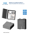
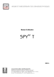
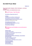
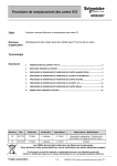
NOTICE D’UTILISATION USER MANUAL Spy RF Référence 09543B ©JRI Maxant 1 Sommaire I. INTRODUCTION ___________________________________________________________________________ 3 A) B) FOURNITURE _____________________________________________________________________________ 3 SYMBOLES ______________________________________________________________________________ 3 II. RECOMMANDATIONS D’INSTALLATION ______________________________________________________ 3 III. PRESENTATION___________________________________________________________________________ 4 IV. INSTALLATION ___________________________________________________________________________ 5 A) B) V. PRECONISATION D’INSTALLATION_______________________________________________________________ 5 INSTALLATION DU SUPPORT___________________________________________________________________ 5 UTILISATION _____________________________________________________________________________ 6 A) B) C) D) E) F) G) H) I) J) L) M) ARRÊT _________________________________________________________________________________ ACTIVATION ______________________________________________________________________________ ATTENTE ________________________________________________________________________________ PROGRAMMATION _________________________________________________________________________ DECLARATION DU SPY RF REFERENCE DANS SIRIUS ________________________________________________ DÉMARRAGE DES MESURES __________________________________________________________________ MODE AUTOMATIQUE _______________________________________________________________________ MODE MANUEL ___________________________________________________________________________ INDICATION D’ALARME ______________________________________________________________________ ARRÊT DES MESURES _______________________________________________________________________ AUTO CONTROLE OU TOP ZONE ________________________________________________________________ FONCTIONNEMENT DES LEDS SUITE A UNE ACTION SUR LE BOUTON POUSSOIR _______________________________ 6 6 6 6 6 6 6 7 7 7 8 8 VI. REMPLACEMENT DE LA PILE _______________________________________________________________ 9 VII. RESET ________________________________________________________________________________ 9 VIII. CARACTERISTIQUES ___________________________________________________________________ 10 IX. GARANTIE ______________________________________________________________________________ 11 X. CONTRAT DE MAINTENANCE ______________________________________________________________ 11 XI. PROTECTION DE L’ENVIRONNEMENT _______________________________________________________ 11 ©JRI Maxant 2 I. INTRODUCTION Félicitations, vous venez de recevoir le SPYRF RéférencE. Cet appareil équipé de 1 ou 2 entrées PT100 permet d’enregistrer la température avec une grande précision et de transmettre les données mémorisées sans fils, par radio fréquence, vers un PC. Cet appareil peut être utilisé comme étalon de référence. a) Fourniture 1 SPY RF Référence 1 Manuel d’utilisation 1 Support mural 1 ou 2 sondes PT100 (selon modèle) 1 protège connectique b) Symboles RECYCLAGE : ne pas jeter dans une décharge ou dans un container de collecte des déchets ménagers. Se conformer à la législation en vigueur pour la mise au rebut. MARQUAGE CE : cet appareil est certifié conforme à la réglementation européenne pour la sécurité électrique, la inflammabilité, l’émission de rayonnements perturbants, et l’immunité aux perturbations électriques environnantes. FCC ID :W45 03330 This device complies with Part 15 of the FCC Rules. Operation is subject to the following two conditions: (1) this device may not cause harmful interference, and (2) this device must accept any interference received, including interference that may cause undesired operation In accordance with FCC requirements, changes or modifications not expressly approved by JRI Maxant could void the user's authority to operate this product. NOTE: This equipment has been tested and found to comply with the limits for a Class A digital device, pursuant to Part 15 of the FCC Rules. These limits are designed to provide reasonable protection against harmful interference when the equipment is operated in a commercial environment. This equipment generates, uses and can radiate radio frequency energy and, if not installed and used in accordance with the instruction manual, may cause harmful interference to radio communications. Operation of this equipment in a residential area is likely to cause harmful interference in which case the user will be required to correct the interference at his own expense. II. RECOMMANDATIONS D’INSTALLATION Le Spy RF est un enregistreur de grandeur physique communiquant sans fil avec un logiciel de la gamme SIRIUS. La communication sans fil est basée sur le principe de la radio fréquence. Comme nous en sommes entourés au quotidien (télé, radio…), on a vite fait de penser que cela fonctionne à tous les coups. C’est vrai si l’on respecte quelques règles basiques concernant le positionnement des appareils, car toute transmission sans fil est sujette à perturbations. a) Sources de perturbations Présence d’obstacle dans le trajet des ondes entre le Spy RF ModeM et le Spy RF (mur, mobilier, personne…) ou à proximité de l’antenne. Epaisseur d’un obstacle dans le trajet des ondes. L’atténuation est plus importante en diagonale que perpendiculairement Une paroi métallique pleine est infranchissable par les ondes. Par contre une paroi métallique ajourée laisse quand même passer les ondes en les atténuant ©JRI Maxant 3 III. PRESENTATION Témoins de fonctionnement et d’alarme Bouton poussoir Trappe de pile Afficheur Connectique Protège connectique IP65 Support mural a) Afficheur Mode enregistrement Remplissage mémoire Mode attente Activité radio Indicateurs de dépassement de seuil N° de la voie Mesure et unité Mode non programmé b) Informations complémentaires Mémoire pleine. Il faut transférer les données c) Connectique Pile faible. Il faut la remplacer. Le SPY RF RéférencE est équipé d’un connecteur rapide facilitant l’installation du capteur. Le capteur peut, le cas échéant, être déconnecté de l’enregistreur pour son remplacement ou pour l’échange de l’enregistreur lui-même. Modèle 1Voie Le connecteur est en vue arrière (coté bornes à souder) ©JRI Maxant Modèle 2 Voies 4 d) Raccordement des sondes 4 3 2 1 Ne jamais dévisser les connecteurs des sondes pour les retirer de l’appareil. Tirez dessus fortement IV. INSTALLATION a) Préconisation d’installation Placer les appareils en hauteur à ~2m et ~30 à 40 cm du plafond pour éviter les obstacles et les passages de personnes. Dans la mesure du possible, placer le Spy RF ModeM dans une position centrale par rapport aux points de mesure. Essayer de les placer de préférence à vue. Au mur, les écarter de préférence de la paroi en utilisant un « Eloigne support mural » (ref 08512) proposé au catalogue. Sur une machine (frigo, étuve, four, chambre froide…), faire dépasser l’antenne. Ne jamais placer les Spy RF horizontalement Si des difficultés persistent il est possible d’utiliser des Spy RF Relay (recepteurs) ou bien connecter un autre Spy RF Modem sur le réseau ethernet b) Installation du support Le support peut être fixé à l’aide de l’adhésif fixé dessus ou bien à l’aide de vis Plan de perçage Possibilité de mettre un dispositif antivol ©JRI Maxant 5 V. UTILISATION a) Arrêt A réception, le SPY RF est à l’arrêt. Seule l’horloge est active. Il ne peut ni émettre ni recevoir. b) Activation Pour activer le SPY RF, appuyer entre 5 et 10’’ sur le bouton : - les 2 leds s’allument puis clignotent simultanément - tous les segments de l’afficheur s’allument également - passage en mode Attente Nota : Un appui >10’’ => aucun effet => reste en arrêt c) Attente Le SPY RF est prêt à recevoir une programmation ou à redémarrer un nouvel enregistrement Le symbole « halt » est allumé : pas de mesure en cours. Démarrage possible sur le bouton poussoir ou l’horodatage. d) Programmation La configuration du SPY RF est réalisée à l’aide du Logiciel Sirius puis transmise au SPY RF par radio fréquence. e) Déclaration du Spy RF RéférencE dans Sirius Avec une version de Sirius antérieure ou égale à 1.5.x, il faut déclarer le Spy RF RéférencE comme étant un Spy RF U1 ou U2. Il est préconfiguré avec sa sonde. ATTENTION à ne pas modifier le choix de la sonde et la résolution A partir de la version 2.0 Sirius, il faut le déclarer en tant que Spy RF RéférencE f) Démarrage des mesures Le SPY RF est muni de 2 modes de démarrage : le mode automatique le mode manuel g) Mode automatique Le SPY RF effectue les acquisitions : immédiatement au démarrage, + ©JRI Maxant Témoin de fonctionnement (vert) : 2’’ => signale le début des mesures Puis clignote toutes les 1min. affichage de la T°C, du N° de la voie, de l’unité de mesure et du taux de remplissage mémoire, la led verte clignote toutes les minutes, 6 la T°, l’indicateur de seuil, le N° de la voie et la led rouge clignotent toutes les 15s en cas de dépassement de seuil. à une date et une heure programmée jj / mm / aa hh / mm / ss + Témoin de fonctionnement (vert) : 2’’ => signale le début des mesures Puis clignote toutes les 1min. h) Mode manuel Par un appui court sur le bouton poussoir + Témoin de fonctionnement (vert) : 2’’ => signale le début des mesures Puis clignote toutes les 1min. Affichage de la T°C, du N° de la voie, de l’unité de mesure et du taux de remplissage mémoire La led verte clignote toutes les minutes i) Indication d’alarme Le SPY RF est muni de plusieurs indicateurs simultanés de dépassement de seuil. Pré alarme Alarme + Indicateur de seuil haut ou bas Témoin d’alarme (rouge) : Clignote toutes les 10’’. Valeur mesurée clignote toutes les 1’’ j) Arrêt des mesures Suivant la programmation, le SPY RF peut s’arrêter ou non. Les différentes possibilités sont : aucun : Une fois la mémoire pleine, les nouvelles valeurs remplacent les plus anciennes mémoire pleine : l’enregistreur s’arrête lorsque le mémoire est pleine. par soft : L’opérateur peut à l’aide de Sirius remettre le SPY RF en mode veille s’il ne l’utilise plus. Par bouton poussoir : valide uniquement si le SPY RF est configuré en mode transport avec démarrage par bouton poussoir. ©JRI Maxant 7 Pour arrêter le SPY RF, appuyer entre 5 et 10’’ sur le bouton : - les 2 leds s’allument puis clignotent alternativement - L’écran s’éteint, Halt s’allume. k) Auto contrôle ou top zone Le type d’action dépend de la configuration du SPY RF. TOP ZONE = Mode Transport et AUTO CONTROLE= Mode stockage. Cette fonction permet de personnaliser une action de vérification des mesures. Un appui court sur le BP. + T° OK (voyant vert) s’allume pendant 10’’. + Témoin d’alarme (rouge) s’allume pendant 10’’. L’action est mémorisée et apparaîtra sur la courbe lors de l’exploitation des données dans le logiciel SIRIUS l) Fonctionnement des leds suite à une action sur le bouton poussoir La led Verte s’allume 2’’ au démarrage des mesure puis clignote toutes les 1’ en enregistrement Fonctionnements spécifiques en fonction du mode d’utilisation de l’appareil : Appareils configurés en mode stockage : Appui BP Mode Arrêt < 5" Entre 5’’ et 10’’ - les 2 leds s’allument puis clignotent simultanément. Led Verte 2" = début des mesures - - - - - Led Verte 10" = auto contrôle - Démarrage des mesures Démarrage BP Démarrage Horodaté Démarrage immédiat Mesure ©JRI Maxant 8 Appareils configurés en mode transport : Appui BP < 5" 5"<appui>10" - les 2 leds s’allument puis clignotent simultanément. Led Verte 2" = début des mesures - - les 2 leds s’allument puis clignotent simultanément = Attente démarrage des mesures les 2 leds s’allument puis clignotent en alternance = arrêt des mesures les 2 leds s’allument puis clignotent en alternance = arrêt des mesures Mode Arrêt Démarrage des mesures Démarrage BP Démarrage Horodaté Démarrage immédiat Mesure VI. Led Verte 10" = Top zone REMPLACEMENT DE LA PILE Quand la pile du SPY RF doit être remplacée, l’afficheur vous le signal par le message suivant PROCEDER AU VIDAGE DE LA MEMOIRE AVANT DE CHANGER LA PILE. NE PAS ATTENDRE QUE LA PILE SOIT ENTIEREMENT VIDEE SINON LES DONNEES SERONT PERDUES Pour remplacer la pile ou effectuer un rest de l’appareil, suivre les étapes suivantes : Changement de la pile 3 2 1 1 b 2 Ne jamais dévisser Cela entraîne une rupture de garantie 3 a Ouvrir la trappe de pile a) Débrancher la pile b) Court-circuiter les 2 pastilles, à l’aide d’un tournevis. c) Connecter la nouvelle pile. d) Changer le joint e) Refermer la trappe de pile. TENIR LA PILE A L’ECART DU FEU, NE PAS ESSAYER DE LA RECHARGER NI DE LA COURT-CIRCUITER N’UTILISER QUE DES PILES FOURNIES PAR JRI (REF : 06569) VII. RESET En cas de bloquage de l’appareil (impossibilité de le rallumer…), efffectuer un reset en procédant de la meme manière qu’un changement de pile. ©JRI Maxant 9 VIII. CARACTERISTIQUES Version PT100 Etendue de mesure Nombre de voies Type d'entrée Résolution Exactitude (à +10°C > T° amb <+40°C Intervalle de mesure Taille mémoire Conditions assignée de fonctionnement Température de stockage Portée radio (en champ libre) Bande radio Durée de vie de la pile ** Dimensions Indice de Protection Conformité CE ERM Conformité FCC -50°C + 125°C 1 ou 2 PT100* appairée / TOR 0.01°C ±0,09°C de -20 à +50°C ±0,2°C de -50 à -20°C ±0,12°C de +50 à +125°C 4s à 90 min 20 000 mesures 10 à +40°C -40 à + 85°C 1 km 868MHz ou 902MHz 2 ans 123x69x30mm IP65 EN 301 489 / EN 61000 / EN 61010 / EN 55022 / EN 300 220 FCC part 15 Version sans sonde -200°C + 300°C 1 ou 2 PT100* / TOR non fournie 0.01°C ±0,05°C + EMT sonde de -50 à +50°C ±0,1°C + EMT sonde au-delà 4s à 90 min 20 000 mesures 10 à +40°C -40 à + 85°C 1 km 868MHz ou 902MHz 2 ans 123x69x30mm IP65 EN 301 489 / EN 61000 / EN 61010 / EN 55022 / EN 300 220 FCC part 15 *PT100 Classe B surmoulée avec câble plat ** Si periode mesure > 2’ sinon 1 an pour 1’, 6 mois pour 10’’, 3 mois pour 4’’ ©JRI Maxant 10 IX. GARANTIE Notre matériel est garanti un an, pièces et main-d'oeuvre, contre tout vice de fabrication, défaut de fonctionnement ou usure anormale. Cette garantie ne s'étend qu'au remplacement des pièces reconnues défectueuses et à la remise en état du matériel en cause revenus FRANCO de port en nos ateliers, à l'exclusion de tous dommages et intérêts ou frais accessoires. Le point de départ de la garantie est la date de facturation du produit concerné. La facture d’achat devra être produite à l’appui de toute demande de mise en jeu de la garantie. Les réparations sous garantie ne prolongent d’aucune façon le délai de garantie accordé au produit lors de sa vente. Les détériorations dues à toute utilisation anormale ou à tout stockage aux intempéries sont exclues de notre garantie. X. CONTRAT DE MAINTENANCE Comment bien optimiser votre installation par radiofréquence? Les systèmes de mesure par radiofréquence communiquent par ondes hertziennes. De nombreux facteurs (changement d’installation, déménagement, cloison supplémentaire, interférence avec un autre système radio...) peuvent toutefois modifier le chemin radio préalablement défini. La radiofréquence requiert donc un suivi périodique par des spécialistes reconnus. C’est pourquoi JRI Maxant a créé pour vous, le contrat de maintenance. Nous simplifions vos démarches en vous apportant une solution clef en main. Cette offre globale de services comprend, la maintenance et un service métrologique ce qui vous permet d’assurer le fonctionnement performant de vos appareils ou de votre installation. Vous n’aurez plus à vous soucier de l’entretien de vos appareils ! Ce contrat de maintenance vous permet de bénéficier pour une durée minimale de 2 ans, de prestations diverses comme : - la vérification annuelle ou biannuelle du matériel - l’extension de garantie - la télémaintenance - l’assistance téléphonique +33 (0) 892 680 933 (0,282 € HT/min) - le remplacement du matériel sur site ou par un retour en usine - la vérification de l’exactitude des mesures (certificat métrologique) - l’accès aux nouvelles versions des logiciels - Un délai d’intervention sur site de 48H ouvrées après identification du défaut par nos experts XI. PROTECTION DE L’ENVIRONNEMENT JRI Maxant recommande à ses clients de mettre au rebut leur matériel de mesure, d'enregistrement inutilisable et/ou irréparable d'une manière appropriée à la protection de l'environnement. Dans la mesure où la production des déchets ne peut être évitée, il y a lieu de réutiliser ceux-ci en procédant au recyclage le mieux adapté aux matériaux considérés et à la protection de l'environnement. Directive RoHS La Directive européenne dite RoHS réglemente et limite la présence de substances dangereuses dans les équipements électroniques et électriques (EEE). Le champ d'application de cette Directive exclut dans son article 2, les "Instruments de surveillance et de contrôle" dont font partie les produits fabriqués par la société JRI Maxant. Néanmoins la société JRI Maxant a décidé d'appliquer l'ensemble des dispositions de cette Directive pour ses nouveaux produits électroniques qui seront conformes à la Directive 2002/95/CE précitée. ©JRI Maxant 11 Summary . I. INTRODUCTION __________________________________________________________________________ 13 A) B) II. EQUIPMENT _____________________________________________________________________________ 13 SYMBOLS ______________________________________________________________________________ 13 INSTALLATION RECOMMENDATIONS _______________________________________________________ 13 A) III. PERTURBATIONS SOURCES __________________________________________________________________ 13 PRESENTATION__________________________________________________________________________ 14 A) B) C) D) DISPLAY _______________________________________________________________________________ COMPLEMENTARY INFORMATION ______________________________________________________________ CONNECTOR ____________________________________________________________________________ CONNECTING PROBES _____________________________________________________________________ 14 14 14 15 IV. INSTALLATION __________________________________________________________________________ 15 A) B) V. INSTALLATION RECOMMENDATIONS ____________________________________________________________ 15 INSTALLATION OF WALL-MOUNTING BRACKET _____________________________________________________ 15 USE ____________________________________________________________________________________ 16 A) B) C) D) E) F) G) H) I) J) K) L) STOP _________________________________________________________________________________ START ________________________________________________________________________________ WAITING MODE __________________________________________________________________________ CONFIGURATION _________________________________________________________________________ SPY RF RÉFÉRENCE DECLARATION IN SIRIUS ____________________________________________________ MEASUREMENT START _____________________________________________________________________ AUTOMATIC START ________________________________________________________________________ MANUAL START __________________________________________________________________________ ALARM VISUALISATION _____________________________________________________________________ MEASUREMENT STOP ______________________________________________________________________ AUTO CONTROL OR TOP ZONE ________________________________________________________________ LEDS AND PUSHBUTTON ACTIONS FUNCTIONING ___________________________________________________ 16 16 16 16 16 16 16 17 17 17 18 18 VI. BATTERY CHANGE _______________________________________________________________________ 19 VII. RESET _______________________________________________________________________________ 19 VIII. FEATURES ____________________________________________________________________________ 19 IX. WARRANTY _____________________________________________________________________________ 20 X. MAINTENANCE CONTRACT ________________________________________________________________ 20 XI. ENVIRONMENT PROTECTION ______________________________________________________________ 20 ©JRI Maxant 12 I. INTRODUCTION Congratulations, you own a SPY RF RéférencE ! This device is equipped with 1 or 2 PT100 inputs. It enables you to record the temperature very accurately and to transfer wireless the recorded data by radio frequency to a PC. This device can be use as a standard. a) Equipment 1 SPY RF Référence 1 user manual 1 wall-mounting bracket 1 or 2 PT100 probe 1 connector b) Symbols RECYCLING : do not throw in a rubbish dump or in a domestic waste container. Comply to the regulation to throw away the device. CE MARKING :this equipment is certified to comply with the European regulation for the electric security, inflammability, disturbing radiation emission and immunity to surrounding electric disturbances. N° FCC : W45 03330 This device complies with Part 15 of the FCC Rules. Operation is subject to the following two conditions: (1) this device may not cause harmful interference, and (2) this device must accept any interference received, including interference that may cause undesired operation In accordance with FCC requirements, changes or modifications not expressly approved by JRI Maxant could void the user's authority to operate this product. NOTE: This equipment has been tested and found to comply with the limits for a Class A digital device, pursuant to Part 15 of the FCC Rules. These limits are designed to provide reasonable protection against harmful interference when the equipment is operated in a commercial environment. This equipment generates, uses and can radiate radio frequency energy and, if not installed and used in accordance with the instruction manual, may cause harmful interference to radio communications. Operation of this equipment in a residential area is likely to cause harmful interference in which case the user will be required to correct the interference at his own expense. II. INSTALLATION RECOMMENDATIONS The Spy RF RéférencE is a temperature recorder able to communicate wirelessly with the operating software SIRIUS. The wireless communication is based on long distance radio frequency contrary to Wifi, Bluetooth, zigbee... Nevertheless, there are rules on recorders positioning that is necessary to respect because wireless communication is subject to perturbations. a) Perturbations sources Presence of obstacles in the way of the waves between the Spy RF ModeM and the Spy Rf (wall, ceiling, person, furniture…) or close to the antenna. Obstacles thickness in the way of the waves. The absorption is more important in diagonal as perpendicularly Waves cannot pass through full metallic walls. On the other hand, a perforated wall allows the waves passing with attenuation ©JRI Maxant 13 III. PRESENTATION Alarm LED (red) Battery trap door Working LED (green) Push button Display Connectors SPY RF RéférencE recorder Wall-mounting bracket Connector IP65 protection a) Display Recording mode Waiting mode Memory status Radio signal Overpassed thresholds indicators Channel N° Measurement and unit Non-programmed mode b) Complementary information Full memory. You must transfer the data to your PC. Low battery. You must change the battery. c) Connector The SPY RF RéférencE is equipped with rapid connector which makes the installation of the probe very easy. The probe can otherwise be disconnected from the recorder to be changed or to change the recorder itself. 1 channel T in °C ©JRI Maxant 2 channels 14 d) Connecting probes 4 3 2 1 Never unscrew the sensor connector to unplug it. Pull out strongly. IV. INSTALLATION a) Installation recommendations Place the devices at ~2m high and around 30 to 40cm from the ceiling to avoid obstacles and moving persons. If possible, place the Spy RF in central position regarding the Spy RF recorders. Try to place them preferably at sight of each other . On the wall, it is preferable to them aside by using the special bracket (ref 08512) of the catalog. Place the antenna above the top the monitored unit (fridge, incubator, oven, cold rooms…),. Never place the Spy RF horizontally. If some difficulties persist, it is possible to use Spy Rf RelaY (repeaters) or to connect another Spy RF ModeM to the Ethernet network (LAN). b) Installation of wall-mounting bracket The bracket can be fixed thanks to its adhesive plaster or it can be screwed. Screwing map Possibility to install a lock against robbery ©JRI Maxant 15 V. USE a) Stop When you receive it, your SPY RF is stopped. Only the time clock is active. It can neither emit nor receive anything. b) Start To start your SPY RF, please press between 5 and 10” on the button: - the 2 LEDs are on and flash at the same time - all the display segments are also on - SPY RF is now in waiting mode Remark: If you press >10’’ => no effect => remains off c) Waiting mode The SPY RF is ready to receive a configuration or to start a new recording session. The symbol “Halt” is on: no measures in progress. Use the pushbutton to start. d) Configuration SPY RF configuration is done from the Sirius software and then transferred into your SPY RF by radio frequency. e) Spy RF RéférencE declaration in Sirius With a sirius software up to 1.5.x version, declare the Spy RF RéférencE as a Spy RF U1 or U2. It is preset with a PT100 sensor. Do try to change the choice of the probe With Sirius 2.0, declare it as a Spy RF RéférencE f) Measurement start The SPY RF has 2 starting mode: automatic start manual start g) Automatic start Your SPY RF starts recording: automatically when it starts, + ©JRI Maxant Working LED (green): 2’’ => starting measurements then flashes every 1 minute 16 It displays the temperature in °C degrees, channel number, measurement unit and memory status. The green LED flashes every minute. The temperature, threshold indicator, channel number and a red LED flashes every 15 sec in case the threshold limit is overpassed. at a programmed date and time: dd / mm / yy hh / mm / ss Working LED (green): 2’’ => starting measurements then flashes every 1 minute + h) Manual start Press shortly on the pushbutton + Working LED (green): 2’’ => starting measurements then flashes every 1 minute It displays the temperature in °C degrees, channel number, measurement unit and memory status. The green LED flashes every minute. i) Alarm visualisation The SPY RF is equipped with different alarm indicators, when a threshold limit is overpassed. Pre alarm Alarm + Threshold indicator High or low Alarm LED (red): Flashes every 15’’. Value measured Flashes every 15” j) Measurement stop Depending on the configuration, the SPY RF can stop recording or not. The different options are: Rolling memory: once the memory is full, the new values replace the old ones. Full memory: the recorder stops when its memory is full. With the software: you can put the SPY RF in standby mode with Sirius when you do not use your recorder. With the pushbutton: this option is valid only if the SPY RF is configured in transport mode with a start by pushbutton. ©JRI Maxant 17 To stop your SPY RF, press between 5 and 10” on the button: - The 2 LEDs are on and then flash alternatively. - The screen goes off, Halt goes on. k) Auto control or top zone The type of action depends on the SPY RF configuration. TOP ZONE = Transport mode and AUTO CONTROL = Storage mode This function enables you to customise an action of measurement check-up. You just have to press shortly on the pushbutton. + T° OK: green LED is on during 10”. + Alarm LED (red) is on during 10”. The action is recorded and will appear on the curve when you process the data with your software Sirius. l) Leds and pushbutton actions functioning The green led is on 2’’ when the measurement starts and then flashes each 1’ in recording mode. Specials functioning regarding the recorder using mode: Device set up in storage mode: Pushbutton pressing < 5" 5’’>pressing<10’’ - The 2 leds are on and flash at the same time. Green led 2" = beginning of measurements - - - - - Green led 10" = auto control - Mode OFF Starting measurements Pushbutton Delayed (date & time) Immediately Mesure Device set up in transportation mode: Pushbutton pressing Mode Off < 5" 5"<appui>10" - The 2 leds are on and flash at the same time. Green led 2" = beginning of measurements - Starting measurements Pushbutton The 2 leds are on and flash at the same time = Waiting for Delayed (date & time) starting measurements Immediately - The 2 LEDs are on and then flash alternatively = ending measurements Mesure Green led 10" = Top zone The 2 LEDs are on and then flash alternatively = ending measurements ©JRI Maxant 18 VI. BATTERY CHANGE When the SPY RF battery has to be replaced, the LCD screen displays the following message: DOWNLOAD THE MEMORY BEFORE CHANGING THE BATTERY. NEVER WAIT UNTIL THE BATTERY IS EMPTY OR THE DATA WILL BE DELETED. To replace the battery or reset the device, follow the instructions below: 3 1 Never unscrew. This will cancel the warranty 2 1 2 Open the battery cover b 3 a a) Unplug the battery connector. b) Short circuit the 2 pins with a screwdriver c) Connect the new battery d) Change the seal e) Close the battery cover KEEP THE BATERY FAR FROM THE FIRE ; DO NOT TRY TO RELOAD OR TO SHORT CIRCUIT IT. USE ONLY BATTERIES SUPPLIED BY JRI (REF 06569) VII. RESET If the device does not work anymore (cannot turn it on…), use the Reset function in the same way as the battery change. VIII. FEATURES Measurement range Number of channels Type of input Resolution Accuracy (at +10°C > amb T°< +40°C) -50°C + 125°C -200°C + 300°C 1 or 2 1 or 2 PT100*supplied/ TOR PT100* not furnished / TOR 0.01°C 0.01°C ±0,09°C from -20 to +50°C ±0,05°C + EMT probe from-50 to +50°C ±0,2°C from -50 to -20°C ±0,1°C + EMT probe outside ±0,12°C from +50 to +125°C Recording interval 4s to 90 min 4s to 90 min Memory size 20 000 measurements 20 000 measures Operating conditions 10 to +40°C 10 to +40°C Temperature for storage -40 to + 85°C -40 to + 85°C Radio range (in free field) 1 km 1 km Radio band 868MHz or 902MHz 868MHz or 902MHz Battery lifetime ** 2 years 2 years Dimensions 123x69x30mm 123x69x30mm Protection level IP65 IP65 CE ERM conformity EN 301 489 / EN 61000 / EN 61010 / EN 301 489 / EN 61000 / EN 61010 / EN 55022 / EN 300 220 EN 55022 / EN 300 220 Conformity FCC FCC part 15 FCC part 15 * Molded PT100 range B with flat cable **If period measures > 2’ wether 1 year for 1’, 6 months for 10’’, 3 months for 4’’ ©JRI Maxant 19 IX. WARRANTY JRI Maxant products carry a one year warranty and guarantee against defects in their components or workmanship. During this period if any product supplied by the Company proves on inspection to be defective, the Company will at its own option replace the same or refund to the Buyer the price of the product. In no circumstances will JRI Maxant' liability exceed the price of the product paid by the buyer or the cost of replacement. JRI Maxant shall not in any event be liable to the Buyer for any indirect or consequential loss or damage costs or expenses whatsoever which might arise out of or in connection with the supply of the product or its consequent use. Consequently, the products warrantee and guarantee specified above, does not cover damage caused by fair wear and tear, abnormal storage conditions, incorrect use, accidental misuse, abuse, neglect, misapplication or modification, or use with non-JRI Maxant' hardware/software. No warranty of fitness for a particular purpose is offered and the user assumes the entire risk of using the product. In line with our policy of continuous development, we reserve the right to amend our product specification without prior notice. X. MAINTENANCE CONTRACT How to optimize your radio frequency installation? RF measuring systems communicate by radio frequency. However, there may be several factors that can modify the radio ways already defined, such as moving from a building, adding walls, … Radio frequency requires thus a periodical follow up performed by specialists. That’s why JRI Maxant has created maintenance contracts. We bring you a global solution which makes your maintenance easier. This overall service offer includes maintenance and also metrological services, which ensure you that your system is fully performant. You won’t worry about your devices maintenance anymore ! With this maintenance contract you will benefit for a minimal period of 2 years from the following advantages: - material verification once or twice a year - warranty extension - telemaintenance - telephone assistance +33 (0) 892 680 933 (0,282 € HT/min) - material replacement on site or by return in our manufacture - metrological certificates: verification of measurement accuracy - access to new software versions and updates - on-site intervention time within 3 open days after problem identification by our experts XI. ENVIRONMENT PROTECTION JRI Maxant recommends to our customers to throw away their measuring and recording devices which are unserviceable and/or beyond repair in a way that is appropriate to environment protection. Insofar as the production of waste cannot be avoided, it is best to re-use them by proceeding with adapted recycling depending on the material used and considering the environment protection. RoHS Directive The ROHS European Directive rules and limits the presence of hazardous substances in electrical and electronic equipments (EEE). In the article 2, the scope of this Directive excludes "9. Monitoring and Control Instruments" and our products are part of this category. Nevertheless, our company has decided to apply the whole dispositions of this Directive for all our new electronic devices which will comply to this 2002/95/CE Directive. ©JRI Maxant 20