1
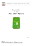
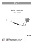
Manuel d’utilisation User Manual 09867 SOMMAIRE I. INTRODUCTION ............................................................................................................................................................ 3 a) Fourniture .................................................................................................................................................................................. 3 b) Symboles ................................................................................................................................................................................... 3 II. PRESENTATION............................................................................................................................................................ 3 III. RECOMMANDATIONS D’INSTALLATION ................................................................................................................... 3 a) Sources de perturbations ......................................................................................................................................................... 3 IV. UTILISATION ................................................................................................................................................................. 4 V. a) Arrêt ........................................................................................................................................................................................... 4 b) Activation ................................................................................................................................................................................... 4 c) Programmation.......................................................................................................................................................................... 4 d) Démarrage des mesures .......................................................................................................................................................... 4 e) Mode automatique .................................................................................................................................................................... 4 f) Mode manuel ............................................................................................................................................................................. 4 g) Indication d’alarme ................................................................................................................................................................... 4 h) Arrêt des mesures..................................................................................................................................................................... 4 i) Auto contrôle ou top zone........................................................................................................................................................ 5 j) Fonctionnement des leds suite à une action sur le bouton poussoir .................................................................................. 5 CARACTERISTIQUES ................................................................................................................................................... 6 VI. GARANTIE ..................................................................................................................................................................... 6 VII. COMMENT BIEN OPTIMISER VOTRE INSTALLATION PAR RADIOFREQUENCE? ................................................. 6 VIII. PROTECTION DE L’ENVIRONNEMENT ....................................................................................................................... 6 TABLE OF CONTENTS .......................................................................................................................................................... 7 ©JRI Maxant 2 I. INTRODUCTION Félicitations, vous venez de recevoir le Mini SPY RF. Cet appareil équipé de 1 Sonde intégrée permettant d’enregistrer à intervalles réguliers les variations de la température ambiante puis de les transmettre sans fils, par radio fréquence, vers un PC. a) Fourniture b) 1 Mini SPY RF ou plusieurs Mini SPY RF 1 Manuel d’utilisation Symboles RECYCLAGE : ne pas jeter dans une décharge ou dans un container de collecte des déchets ménagers. Se conformer à la législation en vigueur pour la mise au rebut. MARQUAGE CE : cet appareil est certifié conforme à la réglementation européenne pour la sécurité électrique, la inflammabilité, l’émission de rayonnements perturbants, et l’immunité aux perturbations électriques environnantes. II. PRESENTATION Led de fonction-nement (verte) Led d’alarme (rouge) Capteur de T° Etiquette de personnalisation Bouton poussoir III. RECOMMANDATIONS D’INSTALLATION Le Mini SPY RF est un enregistreur de grandeur physique communiquant sans fils avec un logiciel de supervision SIRIUS. La communication sans fils est basée sur le principe de la radio fréquence. Comme nous en sommes entourés au quotidien (télé, radio…), on a vite fait de penser que cela fonctionne à tous les coups. C’est vrai si l’on respecte quelques règles basiques concernant le positionnement des appareils, car toute transmission sans fils est sujette à perturbations. a) ©JRI Maxant Sources de perturbations Présence d’obstacle dans le trajet des ondes entre le Spy RF ModeM et le Mini SPY RF (mur, mobilier, personne…) ou à proximité de l’antenne. Une paroi métallique pleine est infranchissable par les ondes. Par contre une paroi métallique ajourée laisse quand même passer les ondes en les atténuant Epaisseur d’un obstacle dans le trajet des ondes. L’atténuation est plus importante en diagonale que perpendiculairement 3 IV. UTILISATION a) Arrêt A réception, le Mini SPY RF est à l’arrêt. Seule l’horloge est active. Il ne peut ni émettre ni recevoir. b) Activation Pour activer le Mini SPY RF, appuyer entre 5 et 10’’ sur le bouton : - les 2 leds s’allument puis clignotent simultanément - passage en mode Attente Nota : Un appui >10’’ => aucun effet => reste en arrêt c) Programmation La configuration du Mini SPY RF est réalisée à l’aide du Logiciel Sirius puis transmise sans fils au SPY RF. d) Démarrage des mesures Le Mini SPY RF est muni de 2 modes de démarrage : le mode automatique le mode manuel e) Mode automatique Le Mini SPY RF effectue les acquisitions : immédiatement à la fin du transfert de la configuration, Témoin fonctionnement (vert) : 2’’ => signale le début des mesures, puis clignote toutes les 1min. à une date et une heure programmée jj / mm / aa hh / mm / ss f) Témoin de fonctionnement (vert) : 2’’ => signale le début des mesures, puis clignote toutes les 1min. Mode manuel Par un appui court sur le bouton poussoir Témoin de fonctionnement (vert) : 2’’ => signale le début des mesures, puis clignote toutes les 1min. g) Indication d’alarme Le Mini SPY RF est muni de plusieurs indicateurs simultanés de dépassement de seuil. Pré alarme : pas d’indication particulière Alarme Témoin d’alarme (rouge) : Clignote toutes les 15’’. h) Arrêt des mesures Suivant la programmation, le Mini SPY RF peut s’arrêter ou non. Les différentes possibilités sont : aucun : Une fois la mémoire pleine, les nouvelles valeurs remplacent les plus anciennes mémoire pleine : l’enregistreur s’arrête lorsque le mémoire est pleine. par soft : L’opérateur peut à l’aide de Sirius remettre le Mini SPY RF en mode veille s’il ne l’utilise plus. ©JRI Maxant 4 Par bouton poussoir : valide uniquement si le MINI SPY RF est configuré en mode transport avec démarrage par bouton poussoir. Pour arrêter le SPY RF, appuyer entre 5 et 10’’ sur le bouton : - les 2 leds s’allument puis clignotent alternativement i) Auto contrôle ou top zone Le type d’action dépend de la configuration du SPY RF. TOP ZONE = Mode Transport et AUTO CONTROLE= Mode stockage. Cette fonction permet de personnaliser une action de vérification des mesures. Un appui court sur le BP. T° OK (voyant vert) s’allume pendant 10’’. Témoin d’alarme (rouge) s’allume pendant 10’’. L’action est mémorisée et apparaîtra sur la courbe lors de l’exploitation des données dans le logiciel SIRIUS j) Fonctionnement des leds suite à une action sur le bouton poussoir La led Verte s’allume 2’’ au démarrage des mesure puis clignote toutes les 1’ en enregistrement Fonctionnements spécifiques en fonction du mode d’utilisation de l’appareil Appareils configurés en mode stockage Appui BP < 5" Entre 5’’ et 10’’ - les 2 leds s’allument puis clignotent simultanément. Attente programmation Led Rouge 2" - Demarrage des mesures Démarrage BP Led Verte 2" = début des mesures - - - - - Led Verte 10" = auto contrôle - Mode Arrêt Démarrage Horodaté Démarrage immédiat Mesure Appareils configurés en mode transport Appui BP Mode Arrêt Attente programmation < 5" 5"<appui>10" - les 2 leds s’allument puis clignotent simultanément. Led Rouge 2" - Led Verte 2" = début des mesures - Demarrage des mesures Démarrage BP Démarrage Horodaté Démarrage immédiat Mesure ©JRI Maxant Led Verte 10" = Top zone les 2 leds s’allument puis clignotent simultanément = Attente démarrage des mesure les 2 leds s’allument puis clignotent en alternance = arrêt des mesures les 2 leds s’allument puis clignotent en alternance = arrêt des mesures 5 V. CARACTERISTIQUES CARACTERISTIQUES Etendue de mesure Nombre de voie Type d'entrée Exactitude Intervalle de mesure Taille mémoire Conditions assignée de fonctionnement Température de stockage Portée radio (en champ libre) Bande radio Durée de vie de la pile (non interchangeable) Dimensions Indice de Protection Conformité CE ERM Mini SPYRF -40 +85°C 1 interne PTC ±0,4°C de -20 à +30°C ±0,5°C hors de cette plage 1min à 90 min 10 000 mesures -40 +85°C -40 + 85°C 45 m max paramétrable 868MHz ou 902MHz 5 ans 85x55x18mm IP68 EN 301 489 / EN 61000 / EN 61010 EN 55022 / EN 300 220 VI. GARANTIE Notre matériel est garanti un an, pièces et main-d'oeuvre, contre tout vice de fabrication, défaut de fonctionnement ou usure anormale. Cette garantie ne s'étend qu'au remplacement des pièces reconnues défectueuses et à la remise en état du matériel en cause revenus FRANCO de port en nos ateliers, à l'exclusion de tous dommages et intérêts ou frais accessoires. Le point de départ de la garantie est la date de facturation du produit concerné. La facture d’achat devra être produite à l’appui de toute demande de mise en jeu de la garantie. Les réparations sous garantie ne prolongent d’aucune façon le délai de garantie accordé au produit lors de sa vente. Les détériorations dues à toute utilisation anormale ou à tout stockage aux intempéries sont exclues de notre garantie. CONTRAT DE MAINTENANCE VII. COMMENT BIEN OPTIMISER VOTRE INSTALLATION PAR RADIOFREQUENCE? Les systèmes de mesure par radiofréquence communiquent par ondes hertziennes. De nombreux facteurs (changement d’installation, déménagement, cloison supplémentaire, interférence avec un autre système radio...) peuvent toutefois modifier le chemin radio préalablement défini. La radiofréquence requiert donc un suivi périodique par des spécialistes reconnus. C’est pourquoi JRI Maxant a créé pour vous, le contrat de maintenance. Nous simplifions vos démarches en vous apportant une solution clef en main. Cette offre globale de services comprend, la maintenance et un service métrologique ce qui vous permet d’assurer le fonctionnement performant de vos appareils ou de votre installation. Vous n’aurez plus à vous soucier de l’entretien de vos appareils ! Ce contrat de maintenance vous permet de bénéficier pour une durée minimale de 2 ans, de prestations diverses comme : - la vérification annuelle ou biannuelle du matériel - l’extension de garantie - la télémaintenance - l’assistance téléphonique +33 (0) 892 680 933 (0,282 € HT/min) - le remplacement du matériel sur site ou par un retour en usine - la vérification de l’exactitude des mesures (certificat métrologique) - l’accès aux nouvelles versions des logiciels - Un délai d’intervention sur site de 48H ouvrées après identification du défaut par nos experts VIII. PROTECTION DE L’ENVIRONNEMENT JRI Maxant recommande à ses clients de mettre au rebut leur matériel de mesure, d'enregistrement inutilisable et/ou irréparable d'une manière appropriée à la protection de l'environnement. Dans la mesure où la production des déchets ne peut être évitée, il y a lieu de réutiliser ceux-ci en procédant au recyclage le mieux adapté aux matériaux considérés et à la protection de l'environnement. DIRECTIVE ROHS La Directive européenne dite RoHS réglemente et limite la présence de substances dangereuses dans les équipements électroniques et électriques (EEE). Cette Directive s'appliquera à compter du 1er juin 2006. Le champs d'application de cette Directive exclut dans son article 2, les "Instruments de surveillance et de contrôle" dont font partie les produits fabriqués par la société JRI Maxant. Nos produits ne sont donc pas concernés par ces nouvelles dispositions. Néanmoins la société JRI Maxant a décidé d'appliquer l'ensemble des dispositions de cette Directive pour ses nouveaux produits électroniques qui seront conformes à la Directive 2002/95/CE précitée, au plus tard le 1er juin 2006. ©JRI Maxant 6 TABLE OF CONTENTS I. INTRODUCTION ............................................................................................................................................................ 8 a) Equipment ................................................................................................................................................................................. 8 b) Symbols ..................................................................................................................................................................................8 II. PRESENTATION............................................................................................................................................................ 8 III. INSTALLATION RECOMMANDATIONS ....................................................................................................................... 8 a) Perturbations sources .............................................................................................................................................................. 8 IV. USE ................................................................................................................................................................................ 9 V. a) Stop ............................................................................................................................................................................................ 9 b) Start ............................................................................................................................................................................................ 9 c) Waiting mode ............................................................................................................................................................................ 9 d) Configuration............................................................................................................................................................................. 9 e) Measurement start .................................................................................................................................................................... 9 f) Automatic start .......................................................................................................................................................................... 9 g) Manual start ............................................................................................................................................................................... 9 h) Alarm visualisation ................................................................................................................................................................... 9 i) Measurement stop .................................................................................................................................................................... 9 j) Auto control or top zone ........................................................................................................................................................ 10 k) Leds and pushbutton actions fonctionning ......................................................................................................................... 10 FEATURES .................................................................................................................................................................. 11 VI. WARRANTY ................................................................................................................................................................. 11 VII. MAINTENANCE CONTRACT ...................................................................................................................................... 11 VIII. ENVIRONMENT PROTECTION ................................................................................................................................... 11 ©JRI Maxant 7 I. INTRODUCTION Congratulations, you own a Mini SPY RF! This device is equipped with 1 internal sensor. It enables you to record the ambient temperature and to transfer wirelessly the recorded data by radio frequency to a PC. a) Equipment b) 1 or several Mini SPYRF 1 user manual Symbols RECYCLING : do not throw in a rubbish dump or in a domestic waste container. Comply to the regulation to throw away the device. CE MARKING : this equipment is certified to comply with the European regulation for the electric security, inflammability, disturbing radiation emission and immunity to surrounding electric disturbances. II. PRESENTATION Running led (green) T° sensor Identification label Alarm led (red) Push button III. INSTALLATION RECOMMANDATIONS The Mini SPY RF is a recorder of physical parameters able to communicate wirelessly with the operating software SIRIUS. The wireless communicatin is based on radio frequency. As we are daily in contact with it (radio, TV…) it is easy to think that it always works. This true if basic rules on recorders positioning are respected concerning because wireless communication is subject to perturbations. a) ©JRI Maxant Perturbations sources Presence of obstacles in the way of the waves between the Mini SPY RF ModeM and the Mini SPY RF (wall, ceiling, person, furniture…) or close to the antena. Obstacles thickness in the way of the waves. The absorption is more important in diagonal as perpendicularly Waves cannot pass through full metallic walls. On the other hand, a perforated wall allows the waves passing with attenuatinon 8 IV. USE a) Stop When you receive it, your Mini SPY RF is stopped. Only the time clock is active. It can neither emit nor receive anything. b) Start To start your Mini SPY RF, please press between 5 and 10” on the button: - the 2 LEDs are on and flash at the same time all the display segments are also on Mini SPY RF is now in waiting mode - Remark: If you press >10’’ => no effect => remains off c) Waiting mode d) The red led will be on 2’’ if you press 5’’ on the push button. In this case, the Mini SPY RF is waiting for programming Configuration Mini SPY RF configuration is done from the Sirius software and then transferred into your Mini SPY RF by radio frequency. e) Measurement start The Mini SPY RF has 2 starting mode: automatic start manual start f) Automatic start Your Mini SPY RF starts recording: automatically when the configuration is transferred, Working LED (green): 2’’ => starting measurements then flashes every 1 minute at a programmed date and time: dd / mm / yy hh / mm / ss g) Working LED (green): 2’’ => starting measurements then flashes every 1 minute Manual start Press shortly on the pushbutton Working LED (green): 2’’ => starting measurements then flashes every 1 minute h) Alarm visualisation The Mini SPY RF is equipped with different alarm indicators, when a threshold limit is overpassed. Alarm LED (red): Flashes every 15’’. i) Measurement stop Depending on the configuration, the Mini SPY RF can stop recording or not. The different options are: Rolling memory: once the memory is full, the new values replace the old ones. ©JRI Maxant 9 Full memory: the recorder stops when its memory is full. With the software: you can put the Mini SPY RF in standby mode with Sirius when you do not use your recorder. With the pushbutton: this option is valid only if the Mini SPY RF is configured in transport mode with a start by pushbutton. To stop your SPY RF, press between 5 and 10” on the button: - The 2 LEDs are on and then flash alternatively. j) Auto control or top zone The type of action depends on the Mini SPY RF configuration. TOP ZONE = Transport mode and AUTO CONTROL = Storage mode. This function enables you to customise an action of measurement check-up. You just have to press shortly on the pushbutton. T° OK (voyant vert) s’allume pendant 10’’. Témoin d’alarme (rouge) s’allume pendant 10’’. The action is recorded and will appear on the curve when you process the data with your software Sirius. k) Leds and pushbutton actions fonctionning The green led is on 2’’ when the measurement strarts and then flash each 1’ in recording mode. Specials fonctionning regarding the recorder using mode Device set up in storage mode Pushbutton pressing < 5" Mode 5’’> pressing <10’’ Red led 2" The 2 leds are on and flash at the same time. - Green led 2" = begining of measurements - - - - - Green led 10" = auto control - OFF - Waiting setup Starting measurements Pushbutton Delayed (date & time) Immediatly Mesure Device set up in transportation mode Pushbutton pressing Mode Off Waiting setup < 5" 5"<appui>10" - The 2 leds are on and flash at the same time. Red led 2" - Green led 2" = begining of measurements - Starting measurements Pushbutton The 2 leds are on and flash at the same time = Waiting for starting measurements Delayed (date & time) Immediatly Mesure ©JRI Maxant - The 2 LEDs are on and then flash alternatively = ending measurements Green led 10" = Top zone The 2 LEDs are on and then flash alternatively = ending measurements 10 V. FEATURES FEATURES Measurement range Number of channels Type of input Accuracy Recording interval Memory size Operating conditions Temperature for storage Radio range (in free field) Radio band Battery lifetime Dimensions Protection level CE ERM conformity Mini SPYRF -40 +85°C 1 internal PTC ±0,4°C from -20 à +30°C ±0,5°C outside 1min to 90 min 10 000 measurements +1ko -30 +70°C -40 + 85°C Max 45 m adjustable 868MHz or 902MHz 5 years 85x55x18mm IP68 EN 301 489 / EN 61000 / EN 61010 EN 55022 / EN 300 220 VI. WARRANTY JRI Maxant products carry a one year warranty and guarantee against defects in their components or workmanship. During this period if any product supplied by the Company proves on inspection to be defective, the Company will at its own option replace the same or refund to the Buyer the price of the product. In no circumstances will JRI Maxant' liability exceed the price of the product paid by the buyer or the cost of replacement. JRI Maxant shall not in any event be liable to the Buyer for any indirect or consequential loss or damage costs or expenses whatsoever which might arise out of or in connection with the supply of the product or its consequent use. Consequently, the products warrantee and guarantee specified above, does not cover damage caused by fair wear and tear, abnormal storage conditions, incorrect use, accidental misuse, abuse, neglect, misapplication or modification, or use with non-JRI Maxant' hardware/software. No warranty of fitness for a particular purpose is offered and the user assumes the entire risk of using the product. In line with our policy of continuous development, we reserve the right to amend our product specification without prior notice. VII. MAINTENANCE CONTRACT JRI Maxant remains at your side... How to optimize your radio frequency installation? RF measuring systems communicate by radio frequency. However, there may be several factors that can modify the radio ways already defined, such as moving from a building, adding walls, … Radio frequency requires thus a periodical follow up performed by specialists. That’s why JRI Maxant has created maintenance contracts. We bring you a global solution which makes your maintenance easier. This overall service offer includes maintenance and also metrological services, which ensure you that your system is fully performant. You won’t worry about your devices maintenance anymore ! With this maintenance contract you will benefit for a minimal period of 2 years from the following advantages: - material verification once or twice a year - warranty extension - telemaintenance - telephone assistance +33 (0) 892 680 933 (0,282 € HT/min) - material replacement on site or by return in our manufacture - metrological certificates: verification of measurement accuracy - access to new software versions and updates - on-site intervention time within 3 open days after problem identification by our experts VIII. ENVIRONMENT PROTECTION JRI Maxant recommends to our customers to throw away their measuring and recording devices which are unserviceable and/or beyond repair in a way that is appropriate to environment protection. Insofar as the production of waste cannot be avoided, it is best to re-use them by proceeding with adapted recycling depending on the material used and considering the environment protection. RoHS Directive The ROHS European Directive rules and limits the presence of hazardous substances in electrical and electronic equipments (EEE). This Directive applies from 1st June 2006. In the article 2, the scope of this Directive excludes "9. Monitoring and Control Instruments" and our products are part of this category. Therefore, JRI Maxant’ products are not concerned by this new directive. Nevertheless, our company has decided to apply the whole dispositions of this Directive for all our new electronic devices which will comply to this 2002/95/CE Directive, on 1st June 2006 at the latest. ©JRI Maxant 11