1
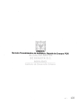
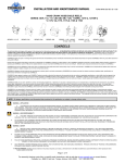
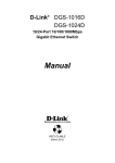
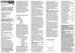
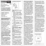
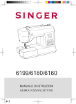
TBN 103 – 206 - 306
Dynamos tachymétriques / Tacho generators /
Tachogeneratoren
MISE EN SERVICE ET UTILISATION
COMMISSIONING AND USE
AUFSTELLUNG UND BETRIEB
PVD 3322 – 01/2003
TBN 103 – 206 - 306
TABLE DES MATIERES / CONTENTS / INHALTSVERZEICHNIS
1.
1.1
1.2
1.3
1.4
2.
2.1
2.2
2.3
2.4
3.
3.1
3.2
3.3
3.4
MISE EN SERVICE ET UTILISATION
2
GENERALITES
PRESCRIPTIONS DE MONTAGE ET D'UTILISATION
MONTAGE POUR TBN 206 ET 306
BALAIS
2
2
3
3
COMMISSIONING AND USE
5
GENERAL
INSTRUCTIONS FOR INSTALLATION AND USE
ASSEMBLY for TBN 200 and 300
BRUSHES
5
5
6
6
AUFSTELLUNG UND BETRIEB
8
ALLGEMEINES
MONTAGE
MONTAGE für TBN 200 und 300
BÜRSTEN
8
8
9
9
Date de la mise en service / Start up date / Erstinbetriebnahme / Fecha de puesta en servicio :
Date de livraison / Delivery date / Lieferdatum / Fecha de entrega :
Type de servomoteur / Servomotor type / Servomotortyp / Tipo de servomotor :
1
PVD 3322 01/2003
TBN 103 – 206 - 306
1. MISE EN SERVICE ET UTILISATION
1.1 GENERALITES
T
B
N
2
06
Les génératrices tachymétriques en kit TBN
sont destinées à fournir l'information de vitesse,
sans retard et sans énergie électrique
auxiliaire.
Montées sans accouplement, donc très rigides,
les génératrices tachymétriques TBN usinées
au micron donnent une image fidèle de la
vitesse instantanée, du passage à vitesse nulle
et du sens de rotation.
TACHY
Bobinée
Nouvelle
Taille 2
6V/ 1 000 tr/min
La présente notice décrit les modèles TBN 100 - 200 - 300.
La génératrice tachymétrique TBN 400 fait l'objet d'une notice séparée.
Les modèles TBN sont prévues entre autres, en association avec les servomoteurs suivants:
Type standard
TBN 103
diamètre mm
Ø 39
RS
RS1
RX
-
TBN 206
Ø 49
RS2…..RS4
RXI - RX3
TBN 306
Ø 64
RS5+ RS6
RX5 + RX6
AXEM
F9-Fl2
MD11-MD13
-
1.2 PRESCRIPTIONS DE MONTAGE ET D'UTILISATION
1.2.1 Réception du matériel
Toutes les tachys font l'objet d'un contrôle rigoureux avant l'envoi.
• Ne pas les manipuler par les câbles;
• Vérifier également que les valeurs de la plaque signalétique sont en conformité avec
les valeurs de votre commande.
En cas de détérioration du matériel dû au transport, le destinataire doit immédiatement faire des
réserves auprès du transporteur par lettre recommandée, sous 24 h.
1.2.2 Stockage
En attendant le montage, le matériel doit être entreposé dans un endroit sec, sans variation brutale de
température pour éviter la condensation. Si le matériel doit être entreposé longtemps, vérifier si le bout
d'arbre et la face de la bride sont toujours bien enduits d'un produit anticorrosion.
2
PVD 3322 01/2003
TBN 103 – 206 - 306
1.2.3 Livraison
Les tachys TBN 103 sont en principe livrées montées sur les servomoteurs. Les génératrices
tachymétriques TBN 206 et 306 sont livrées assemblées (rotor - stator), avec bague de serrage sur le
rotor.
Les vis de fixation avec rondelles sont jointes séparément dans un sachet.
Si par inadvertance, le rotor est déboîté du stator, retirer les balais (délicatement) comme indiqué au
chapitre 1.4. Réemboiter le rotor dans le stator et suivre les instructions de montage. Ensuite replacer
les balais.
1.3 MONTAGE POUR TBN 206 ET 306
Pour le montage des TBN 103, nous consulter
Les génératrices tachymétriques PARVEX sont des instruments de mesure à manipuler avec
précaution, dans de bonnes conditions de propreté. Eviter absolument la présence d'huile ou de
copeaux. Ne pas prendre le rotor par le collecteur. Les traces de doigts que l'on peut éliminer par
nettoyage à l'alcool, amèneraient des anomalies dans le fonctionnement de la génératrice.
Voir pages 11 - 12 pour les dimensions d'arbre et de bride et la qualité géométrique demandée.
La cote 2±0.2 entre la face d'appui de la tachy et le collet de l'arbre, peut être obtenue à l'aide de
rondelle de calage.
L'interface étant respectée, présenter la génératrice sur le bout d'arbre et faire glisser l'ensemble rotor
et stator jusqu'à la face d'appui.
Fixer le stator avec les 2 vis et rondelles. Couple de serrage pour TBN 200 6 + cm.daN, pour TBN 300
14 + cm.daN.
2
0
4
0
Vérifier que le rotor est en appui sur le collet de l'arbre, puis serrer progressivement les 3 vis de la
bague de serrage. Couple de serrage : 14 + cm.daN.
4
0
1.4 BALAIS
La durée de vie des balais est très longue, une vérification toutes les 5000 h est souhaitable. Eviter de
démonter les balais sans nécessité
1.4.1 Démontage et montage du bouchon
Bouchon
plug
Kappe
Démontage : Utiliser un tournevis pour faire levier sur la base du
bouchon ; celui-ci est simplement emmanché sur un cône
inversé.
Montage :
Placer le bouchon sur la pièce terminale puis pousser
dessus pour le descendre en place. S'assurer que la
lèvre inférieure du bouchon soit bien en contact avec la
collerette du porte-balai S'assurer de la présence du joint
pour les tachys TBN 206.
3
PVD 3322 01/2003
TBN 103 – 206 - 306
1.4.2 Vérification de l'usure des balais
il est possible de vérifier l'usure des balais sans les démonter :
Introduire une tige métallique (trombone dépliée) de Ø 0,8 maxi par le
trou de la pièce terminale. Agir avec précaution, le shunt du balai et le
ressort sont fragiles. Mesurer la cote X puis comparer avec les valeurs
suivantes:
Balai neuf X = 7,5 mm
Balai usé X = 13 mm
1.4.3 Démontage et montage des balais
Démontage Utiliser une tige métallique Ø 1 maxi pliée en forme de U
(par exemple un morceau de trombone). Placer cette tige
sous la pièce terminale et faire levier vers le haut.
Montage
Introduire une tige métallique (trombone) de Ø 8 maxi par
l'orifice de la pièce terminale, dans le ressort pour le
redresser.
Monter le balai dans la chemise du porte-balai.
Descendre la pièce terminale puis l'emmancher par
pression sur le cône inversé de la chemise. Agir avec
précaution. le shunt du balai et le ressort étant fragiles.
Remettre le bouchon caoutchouc par pression.
Balais de rechange .
TBN 100
TBN 200
300
Nbre de
balais
2
4
4
Référence du balai
Référence du bouchon
283672R0001
282779P0001
4
PVD 3322 01/2003
TBN 103 – 206 - 306
2. COMMISSIONING AND USE
2.1 GENERAL
The TBN precision tacho generators are designed for high precision speed monitoring. They supply a
voltage proportional to the speed, without delay and without additional energy.
This brochure describes the TBN 100 - 200 - 300 type.
The TBN 400 tacho is described in a separate brochure.
The TBN tachos are fitted in association with the following servomotors :
Standard typ
TBN 103
diameter mrn
Ø 39
RS
RS1
RX
-
TBN 206
Ø 49
RS2…..RS4
RXI - RX3
TBN 306
Ø 64
RS5+ RS6
RX5 + RX6
AXEM
F9-Fl2
MD11-MD13
-
2.2 INSTRUCTIONS FOR INSTALLATION AND USE
2.2.1 Equipment delivery
All tachos undergo a thorough quality control procedure before dispatch:
• Do not hold tachos by the cables
• Check that the information on the identification plate corresponds to your order.
if the equipment has been damaged in transit, the recipient should immediately complain to the carrier
by registered letter within 24 hours.
2.2.2 Storage
Before installation, the material should be stored in a dry place without large temperature variations in
order to prevent condensation.
if it is to be stored for a long time, check that the end of the shaft and the face of the flange are always
coated with an anti-corrosion product.
5
PVD 3322 01/2003
TBN 103 – 206 - 306
2.2.3 Delivery
TBN 103 are normally already mounted on the servomotors.
The TBN tachometers are supplied assembled (rotor and stator) with lock ring on the rotor.
Stator fastening screws and washers are enclosed in a bag.
If, by inadvertence, when assembling, the rotor is disconnected from the stator, remove the brushes as
indicated in § 2.4, reassemble rotor and stator and follow the assembly instructions. Then replace the
brushes.
2.3 ASSEMBLY for TBN 200 and 300
(For TBN 1 00 assembly, consult us)
The TBN tacho-generators are metering instruments and must be handled with care and in very clean
conditions. Avoid absolutely the presence of oil or dust. Do not handle the rotor via the commutator.
Fingermarks, that can be removed by cleaning with alcohol, would produce anomalies in the operation
of the generator.
See page 11 - 12 for the shaft and flange dimensions and the geometrical quality required.
Size 2±0.2 between the bearing face of the tachometer and the shaft shoulder can be obtained using
adjusting washers.
After checking the geometry, place the generator on the shaft end and slip the rotor/stator assembly
up to the bearing face.
Fasten the stator with the two screws and washers.
Torque : 6 + cm.daN for TBN 200 and 14 + cm.daN for TBN 300.
4
0
2
0
Check the correct location of the rotor on the shaft shoulder, then gradually tighten up the three
screws of the clamping ring.
Torque : 14 + cm daN.
4
0
2.4 BRUSHES
The technological improvements give more than 1 0000 operating hours between maintenance. Brush
wisar control could be made every 5000 h. Do not disassembly if not necessary.
2.4.1 Disassembly and monting the cap
Bouchon
plug
Kappe
Disassembly : Use a screwdriver as lever on the base of the cap.
Mounting :
Push the cap on the top to lower it in place. Make sure
that the lower lip is in contact with the brush holder flange.
6
PVD 3322 01/2003
TBN 103 – 206 - 306
2.4.2 Checkinq the wear on the brushes
For ex : every 5 000 h.
Take the cap off. Checking without disassembling the brush : insert a
Ø 0,8 dia. max metal rod through the opening in the terminal section.
Operate carefully because shunt ant spring are fragile. Measure the
size X then compare with the following values :
New brush X = 7.5 mm
Worn brush X = 13 mm
2.4.3 Brushes disassembly and mounting
Disassembly:
Use a Ø 1 max metal rod bent to U form (for
example a bit of paperclip). Place this rod under the terminal section
and lever upwards.
Mounting : insert a Ø 8 max metal rod (paperclip) through the opening
in the terminal part, in the spring to straighten it.
install the brush in the brush-holder sleeve. Lower the terminal section
then press it onto matched tapered surface of the sleeve.
Operate carefully, shunt ont spring are fragile.
Put the cap as 4.1.
SPARE - PARTS
TBN 100
TBN 200
300
Brush QY
2
4
4
Code for 1 brush
Code for 1 cap
283672R0001
282779P0001
7
PVD 3322 01/2003
TBN 103 – 206 - 306
3. AUFSTELLUNG UND BETRIEB
3.1 ALLGEMEINES
Die permanenterregte Tachodynamos von Typ TBN sind als Meßwertaufnehmer eingesetzt.
Durch die direkte Montage der Hohlwellen-Präzisionstachogeneratoren auf die Motorwelle wird eine
sehr hohe Steifigkeit erreicht; diese führt zu einer exakten Geschwindigkeitswiedergabe sowohl bei
hohen Drehzahlen als auch bei Schleichdrehzahlen
Diese Anweisung beschreibt die TBN 100 - 200 - 300 Typen.
Die TBN 400 ist in ein separate Anweisung beschreibt. TBN Typen sind in zusamenhang mit die
folgenden Servomotoren vorgesehen.
Standard Typen
TBN 103
Durchmesser mm
Ø 39
RS
RS1
RX
-
TBN 206
Ø 49
RS2…..RS4
RXI - RX3
TBN 306
Ø 64
RS5+ RS6
RX5 + RX6
AXEM
F9-Fl2
MD11-MD13
-
3.2 MONTAGE
3.2.1 Empfang des Materials
Alle Tachos werden vor dem Versand sorgfaltig überprüft.
• Die Tachos dürfen nicht mit Hilfe der Kabel bewegt werden;
• Vergewissern Sie sich, daß die Leistungsschilddaten mit den in Ihrer Bestellung
gemachten Angaben übereinstimmen.
Falls das Material während des Transports beschädigt worden sein sollte, muß dies dem Zulieferer
innerhalb von 24 Stunden per Einschreiben mitgeteilt werden.
3.2.2 Lagerung
Wenn der Tacho nicht sofort aufgestellt wird, muß er an einem trockenen Ort mit gleichbleibender
Temperatur gelagert werden, um das Auftreten von Kondenswasser zu vermeiden. Bei langfristiger
Lagerung ist darauf zu achten, daß das wellenende und die Flanschoberfläche stets vollständig mit
einem Rostschutzmittel bedeckt sind.
8
PVD 3322 01/2003
TBN 103 – 206 - 306
3.2.3 Lieferung
Die Tachometer TBN werden montiert geliefert (Rotor und Stator), mit Klemmring auf dem Rotor.
Die Befestigungsschrauben mit Scheiben sind in einem Säckchen beigefügt.
Falls aus Versehen der Rotor aus dem Stator heraugezogen wird, sind die Bürsten wie in § 3-4
angegeben (vorsichtig) herauszunehmen. Der Rotor wird germäss Montagevorschrift in den Stator
montiert.
Danach Bürsten montieren.
3.3 MONTAGE für TBN 200 und 300
Für TBN 100 Einbau, bitte Werk anfragen.
Die Tacho generatoren TBN sind Messinstrumente, die unter guten Sauberkeitsbedingungen mit
Vorsicht zu handhaben sind. Die Nähe von Öl und Spänen ist unbedingt zu vermeiden.
Der Rotor nicht durch den Kollektor handhaben. Fingerspuren, die man durch Reinigung mit Alkohol
entfernen kann, würden Störungen im Betrieb des Generators verursachen.
Siehe Abb. 2 für die Wellen-und Flanschabmessungen und die gewünschten geometrischen
Toleranzen.
Das Mass 2±0.2 zwischen Auflagefläche des Tachogenerators und Wellenbund kann mit Hilfe von
Ausgleichscheiben erhalten werden.
Unter Beachtung der Anbaufläche den Generator am Wellenstumpf anordnen und die Rotor-StatorEinheit bis zur Auflagefläche gleiten lassen.
Stator mit den beiden Schrauben und Unterlegscheiben befestigen.
Drehmoment = 6 + cm.daN für TBN 200 und 14 + cm.daN für TBN 300.
4
0
2
0
Prüfen, ob der Rotor auf dem Wellenbund aufliegt, dann die drei Schrauben des Spannring langsam
anziehen.
Drehmoment = 14 + cm.daN
4
0
3.4 BÜRSTEN
Die Bürsten sind wartungsfrei wahrend der Kugellagerlebensdauer des Antriebs. Vermeiden Sie
unnötige Demontage.
3.4.1 Demontage und montage der Kappe
Bouchon
plug
Kappe
Demontage : Ein Schraubenzieher verwenden, um eine Hebelwirkung
an der Verschlussbasis zu erhalten; der Kappe ist
einfach auf einen umgekehrten Kegel eingerastet.
Montage:
Kappe das Abschlussteil aufbringen, drücken bis zum
einrasten.
Sich vergewissern, dass die untere Lippe des Kappe mit
dem Bürstenhalterbund in Berührung liegt.
9
PVD 3322 01/2003
TBN 103 – 206 - 306
3.4.2 Uberprüfung vom Bürstenverschleiß
Z.B. alle 5 000 Betrieb stunden.
Überprüfung ohne Ausbau der Bürste, mit z.B. eine Büroklammer.
Ein Metallstift Ø 0,8 max. durch die Öffnung des Abschlussteils
einführen
Vorsichtig vorgehen, da die Litze der Bürste und die Feder empfindlich
sind.
Absand X messen, dann mit folgenden Werten vergleichen :
Neue Bürste X = 7,5 mm
Abgenutzte Bürste X = 1 3 mm
3.4.3 Demontage und montage der Bürste
Demontage:
Ein in U-formigen gebogenen Metallstift Ø 1 max.
verwenden (z.B. Teil einer Büroklammer).
Diesen Stift unter dem Abschlussteil anordnen und eine
Hebelbewegung noch oben machen.
Montage :
Eine Metallstift Ø 8 max. durch die Öffnung des
Abschlussteils in die Feder einführen, um diese
aufzurichten.
Bürste in den Köcher des Bürstenhalters montieren.
Abschlussteil senken und drücken bis zum einrasten auf
dem Köcher.
Vorsichtig vorgehen, da die Litze der Bürste und die
Feder empfindlich sind.
Kappe wieder einrasten.
ERSATZTEILE
Bürste mit Feder, Litze und Abschlussteil
TBN 100
TBN 200
300
Bürsten
Anzohl
2
4
4
Referenz für 1
Bürste
Referenz für 1 Kappe
283672R0001
282779P0001
10
PVD 3322 01/2003
TBN 103 – 206 - 306
TBN 103
Interface pour montage
Interface for mounting
Schnittstelle für Montage
TBN 206
Encombrement
Dimensions
Abmeβungen
11
PVD 3322 01/2003
TBN 103 – 206 - 306
TBN 306
SPECIFICATIONS / KENNDATEN
Fem à 1 000 tr/min. à vide
EMF / 1000 rpm (open circuit) / EMK / 1000 min-1
Ecart de bidirectionnalité de FEM
Bidirectional tolerance / Abweichung Rechts-Linkslauf
Ondulation résiduelle crête à crête. (Filtre / Filter. RC Filter 800 Hz)
Peak-to-Peak ripple / Restwelligkeit (Spitze-Spitze)
Linéarité rapportée à 3 600 tr/min.
Linearity with reference to 3 600 rpm
Linearität (bezogen auf 3 600 min-1)
Courant Max thermique
Maximum permissible current / Max. zul. Strom
Vitesse maxi mécanique
Maximum speed / Maximal Drehzahl
Moment d'inertie / Rotor moment of inertia / Laüfertragheitsmoment
Dérive de la FEM avec la température
Temperature coefficient / Abweichung der EMK/°C
Résistance d'induit à 25°C
Rotor teminal resistance at 25°C / Ankewiderstand
Self inductance / inductance / Induktivität
Classe d'isolation / Insulation class / Isolierklass
Classe de protection / Degree of protection / Schutzart
Masse / Net weigt / Gewicht
12
PVD 3322 01/2003
TBN 103
TBN 206
TBN306
V
3
6
6
%Ke
<1
<1
<1
%U
≤5
≤3
≤2
%
≤ 0.2
≤ 0.15
≤ 0.15
mA
15
15
25
10 000
10 000
6 000
0.15
0.5
2.5
%/°C
- 0.015
- 0.015
- 0.015
Ω
60
47
11
mH
14
IP 40
B
120
11
IP 40
B
120
6
IP 40
B
250
tr/min.
rpm/Upm
Kgm2 10-5
g
SSD Parvex SAS
8, avenue du Lac – BP249
F-21007 Dijon Cedex
Tel : +33 (0)3 80 42 41 40
Fax : +33 (0)3 80 42 41 23
www.SSDdrives.com
PARVEX PRODUCT RANGE
1 - « BRUSHLESS » SERVODRIVES
•
BRUSHLESS SERVOMOTORS
- Very high torque/inertia ratio (high dynamic performance machinery):
NX -HX - HXA
NX - LX
- High rotor inertia for better inertia load matching:
HS – LS
- Varied geometrical choice :
short motors range HS - LS
or small diameter motors : HD, LD
- Voltages to suit different mains supplies :
230V three-phases for «L – NX series»
400V, 460V three-phases for «H – NX series»
•
•
1 to 320
0,45 to 64
N.m
N.m
3,3 to 31
N.m
3,3 to 31
9 to 100
N.m
N.m
"DIGIVEX DRIVE" DIGITAL SERVOAMPLIFIERS
Single -Axis :
DSD
Compact Single-Axis :
DµD, DLD
P owe r Single -Axis :
DP D
Multiple-Axis : DMD
"PARVEX MOTION EXPLORER" ADJUSTING SOFTWARE
2 - SPINDLE DRIVES
•
•
SPINDLE SYNCHRONOUS MOTORS
"HV" Compact Series
"HW" Electrospindle,frameless, water-cooled motor
"DIGIVEX" DIGITAL SERVOAMPLIFIERS
From 5 to 110 kW
up to 60,000 rpm
3 - DC SERVODRIVES
•
•
•
"AXEM", "RS" SERIES SERVOMOTORS
"RTS" SERVOAMPLIFIERS
"RTE" SERVOAMPLIFIERS for DC motors + resolver giving position measurement
0.08 to 13 N.m
4 - SPECIAL ADAPTATION SERVODRIVES
•
•
"EX" SERVOMOTORS for explosive atmosphere
"AXL" COMPACT SERIES SERVOREDUCERS
5 - POSITIONING SYSTEMS
•
•
•
•
Numerical Controls « CYBER 4000 » 1 to 4 axes
"CYBER 2000" NC 1 to 2 axes
VARIABLE SPEED DRIVE - POSITIONER
Single -Axis :
DSM
P owe r Single -Axis :
DP M
Multiple-Axis :
DMM
ADJUSTMENT AND PROGRAMMING SOFTWARE PARVEX MOTION EXPLORER
5 to 700 N.m