1
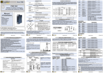
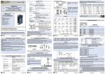
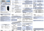
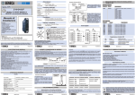
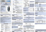
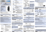
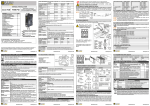
POWER SUPPLY POWER SUPPLY PDM PDM Line Line 19 ..28 VAC a 50 ..60 Hz 2 3 19 - 28 V 10 - 40 V Typical: 1.5 W, Max: 2.5 W Consumption EN Terminals 2 and 3 can be used to provide the module with power supply as an alternative to connection using the PDM-DIN bus.The upper limits must not be exceeded as this can seriously damage the module. If the power supply source is not protected against overload, a safety fuse with a max. permissible value of 2.5 A must be installed in the power supply line. 10 ..40 VDC Voltage ENVIRONMENTAL CONDITION PDM-5RO Modbus Module with 5 relay for Digital Outputs Temperature -10 ..+65°C Humidity 30 ..90% a 40°C non condensing Altitude Up to 2000 m a.s.l. Storage Temperature -20 ..+85°C Protection IP20 DIGITAL OUTPUTS Z-D-OUT-1 Removable 3-way crew terminals, 3,5 pitch Rear IDC10 connector for DIN 46277 rail Connections COMUNE 7 N.A.1 #1 CONNECTIONS Installation Manual 12 Dimensions L: 100 mm; H: 112 mm; W: 17,5 mm Box PBT, Black ISOLAMENTI ISOLATIONS EN61010-1/2001 (safety). All circuits must be isolated from the other circuits under dangerous voltage with double isolation. The power supply transformer must comply with En60742: “Isolated transformers and safety transformers”. 6bis Av. Dr Schweitzer - 69881 MEYZIEU Cedex- FRANCE Tel. +33(0)4 72 14 15 40 - Fax +33(0)4 72 14 15 41 For manuals and configuration software, please visit www.pyrocontrole.com This document is property of Pyrocontrole. Duplication and reprodution are forbidden, if not authorized. Contents of the present documentation refers to products and technologies described in it. All technical data contained in the document may be modified without prior notice Content of this documentation is subject to periodical revision. 694080A00 ED1 ENGLISH 1/8 694080A00 ED1 inductive. 2 Pull-out terminals, section 2.5 mm . Possibility of setting relays as N.O. or N.C. (rest status). Setting of relay safety status at start-up or in the event of no communication. Safety time settable from 0,5 s to 2,5 s. Possibility of ON-LINE configuration.RS485 serial communication with Modbus Rtu housed in the DIN guide. The terminals can still be used. Insertion into and removal from bus without interrupting communication or system power supply. Communication times below 10 ms (@ 38400 Baud). Connection distance up to 1200 m. N.A.4 LED STATE Meaning of LEDS #5 11 N.A.5 PWR FAIL On Blinking On Blinking On Blinking On Power supply presence. Error settings. Fault/Failure. Received data from RS485. Verify the connection. Received data from RS485. Verify the connection. 4 5 6 POWER SUPPLY AND MODBUS INTERFACE Drop length 2m INPUTS 5 SPST N.O .relay outputs with common line Number of Channels 5 Maximum rated current 5A Maximum switching voltage 250 VAC Relay working voltage 24 VDC Pick-Up Relay 18 V Drop-Out Relay 2,4 V Relay absorbed current 9 mA Operate / release time relay 5/2 ms 694080A00 ED1 RS485 B ENGLISH 7/8 DIP-switch settings The DIP-switches position defines the module Modbus communication parameters: Address and Baud Rate. In the following figure the Baud Rate and Address values are listed as a function of the DIP-switches position: POSITION BAUD RATE POSITION ADRESS POSITION 00xxxxxxxx 9600 xx000001xx # 1 xxxxxxxxx0 Disable 01xxxxxxxx 19200 xx000010xx # 2 xxxxxxxxx1 Enable 10xxxxxxxx 38400 TERMINATOR ..... ..... 11xxxxxxxx 57600 POSITION BAUD RATE POSITION ADRESS xx000000 From EEprom xx000000 xx111111xx # 63 From EEprom Note: when switches from 3 to 8 are in OFF, comunication settings are retrieved from Eeprom, You can set parameters with PDM Studio Software In the figure the meaning of the IDC10 connector pins is showed, in the case the user decides to provide the signals directly through it. General: In the Modbus register 40002 is possible to see the state of outputs or change the state of them. Bits 0 to 4 in 40002 register respectively represent the status of output from 1 to 5. In case of PDM-DIN accessories use, the signals may be provided by terminal blocks. The figure shows the meaning of the terminals and the position of the DIP-switch for network termination (not used in case of Modbus network). GNDSHLD: Shield to protect the connection cables ( recommended). Holding register IDC 10 Besides you can set up the output in a state of security when the bus communication is lost. MODBUS REGISTER PDM-DIN-C-2S Accessory Use ENGLISH 2/8 694080A00 ED1 Digital Outputs Power Supply AC + 1 Type output ENGLISH 5/8 694080A00 ED1 Rear Connector (IDC10) Power Supply AC- - Modbus protocol / Communication parameters : 38400 8,N,1 Addr. 1 - Digital Outputs : DISABLE - Statesafe : DISABLE - Safetime : DISABLE - Inversion relay status : DISABLE DIP SWITCH STATUS Power Supply and MODBUS interface are available by using the bus for the DIN rail, by the rear IDC10 connector or by PDM-DIN accessories. RS485 A Factory settings Modification of standard parameters is possible by using configuration software PDM Studio (www.pyrocontrole.com). For more information about a list of all registers and their functions consult the PDM General User manual. Scheme 1 1200 m TX All DIP-switch in OFF Position : 1) Install the modules on the DIN rail (max 120). 2) Connect the remote modules using cables of proper length. On the table the following data about the cables length are provided: -Bus Length: Modbus network maximum length as a function of the Baud rate. It is the lenght of the cables which connect the two bus terminators modules (see Scheme 1). -Drop Length: maximum length of a drop line (see Scheme 1) Bus Length LEDS Signaling RX Connection for RS485 communication using the Modbus master system as an alternative to the PDM-DIN bus. Note: the indication of the RS485 connection polarity is not standardised and in some masters may be inverted. Inserting on the DIN rail As it is illustrated in the next figure: 1) Insert the rear IDC10 connector on a DIN rail free slot (the inserting is univocal since the connectors are polarized). 2) Tighten the two locks placed at the sides of the rear IDC10 connector to fix the module. RS485 GND Active status output 4. See register 40005.0 Active status output 5. See register 40005.0 For the best performances, the use of special shielded cables is recommended The module is designed to be installed in vertical position on a DIN 46277 rail. In order to ensure optimum performance and the longest working life, the module(s) must be supplied adequate ventilation and no raceways or other objects that obstruct the ventilation slots. Never install modules above sources of heat; we recommend installation in the lower part of the control panel. Electrical Connections Technical Specifications OUTPUT 4 OUTPUT 5 N.A.3 protocol, maximum 32 nodes. 2500 Vac output insulation with respect to remaining low voltage circuits. Power supply and serial connection wiring facilitated by means of a bus that can be Active status output 3. See register 40005.0 00004 00005 10 ENGLISH 3/8 Installation Rules General Specifications 5 SPST relay outputs N.O. with common line, capacity 5 A-250 Vac resistive, 2 A Active status output 2. See register 40005.0 OUTPUT 3 #4 Modbus connection rules ADDITIONAL NOTES : : Use in Pollution Degree 2 Environment . Power Supply must be Class 2. When supplied by an Isolated Limited Voltage/Limited Current power supply a fuse rated max 2.5 A shall be installed in the field. OUTPUT 2 00003 N.A.2 The module complies with the following standards: PYROCONTROLE, Groupe Chauvin Arnoux 00002 9 GND B(-) A(+) EN61000-6-2/2006-10 (electromagnetic immunity, industrial environment) Active status output 1. See register 40005.0 8 MODBUS RS485 EN61000-6-4/2002-10 (electromagnetic emission, industrial environment). OUTPUT 1 #3 STANDARDS 1500 VAC a tre punti: Description 00001 #2 DIMENSIONS / BOX Contents: - General Specifications - Technical Specifications - Installation Rules - Electrical connections - Modbus connections rules - DIP-switches settings - Digital outputs - Leds Signaling - Factory Settings Note: The maximum current that can flow through the COMMON terminal is 12A Coil register Name Register 694080A00 ED1 ENGLISH 4/8 Register 40002 Name OUTPUT Description Input 1: 40002.0 Input 2: 40002.1 Input 3: 40002.2 Input 4: 40002.3 Input 5: 40002.4 Active status of the output is obtained by setting the respective bits 694080A00 ED1 ENGLISH 6/8 Disposal of Electrical & Electronic Equipment (Applicable throughout the European Union and other European countries with separate collections programs). This symbol, found on your producr or on its packaging, indicates that this product should not be treated as household waste when you wish to dispose of it. Instead, it should be handed over to an applicable collection point for the recycling of electrical & electronic equipment. By ensuring this product is didposed of correctly, you will help prevent potential negative consequences to the environment and human health, which could otherwise be caused by inappropriate disposal of this product. The recycling of materials will help to conserve natural resources. For more detailed information about the recycling of the product, please contact your local city office, waste disposal service of the retail store where you purchased this product. 694080A00 ED1 ENGLISH 8/8