1
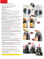
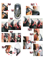
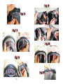
Accessori Accessories Accessoires Zubehör Accesorios
Carica Batterie
Battery charger
Batterieladegerät
Chargeur de batterie
Cargador de baterías
Batteria
Battery
Batterie
Batterie
Batería
Coperchio tastiera
Control pad cover plate
Abdeckung der Tastatur
Couvercle clavier
Tapa del teclado
Vite fissaggio microfono
Microphone fixing screw
Befestigungsschraube für das Mikrofon
Vis de fixation du microphone
Tornillo de fijación para micrófono
LOCATELLI S.p.A.
Via Resistenza, 5/A 24030 Almenno S.Bartolomeo (BG),Italy
Tel.+39035553101 Fax +39035553093
www.airoh.com e-mail [email protected]
TROY
ISTRUZIONI DI MONTAGGIO
INSTRUCTIONS
GEBRAUCHSANLEITUNGEN
INSTRUCCIONES
ITALIANO
ENGLISH
Istruzioni di Montaggio del sistema Airoh AW-Conn sul Modello Jet Troy
Instructions for Assembly of the Airoh AW-Conn System on the Jet Troy Model
Composizione del Kit; il kit Airoh AW-Conn, indicato in Fig. 1, e' composto da:
1)Sistema di trasmissione completo, assemblato ai guanciali interni specifici,
2)Coperchio tastiera esterno con la sede specifica per la tastiera di comando,
3)Trasformatore per ricarica batteria.
4)Vite di fissaggio microfono.
Preparazione del casco,
Procedi a disporre tutto il materiale su un tavolo in posizione comoda.
Per procedere con il montaggio, e' necessario rimuovere la cuffia di comfort interna ed i guanciali in polistirolo, come di seguito
indicato:
1)Tira il primo guanciale verso l'interno e sgancia il bottone automatico posto sotto lo stesso, Fig. 2; effettua la stessa operazione
anche sul lato opposto.
2)Tira verso l'esterno del casco e sgancia le tre linguette di fissaggio anteriori della cuffia di comfort, Fig. 3.
3)Tira verso il basso e sgancia le tre linguette di fissaggio posteriori della cuffia di comfort, Fig. 4.
4)Estrai la cuffia.
5)Sfila ed estrai il primo guanciale in polistirolo facendolo ruotare dalla parte posteriore verso l'anteriore, come indicato in Fig.5;
Ripeti l'operazione con l'altro guanciale.
6)Rimuovi ora il coperchio AW-Conn, esterno alla calotta, spingendo i ganci interni verso l'esterno del casco, Fig. 6.
Montaggio del sistema AW-Conn;
Attenzione! le varie parti del sistema sono collegate tra loro tramite fili elettrici; durante le successive operazioni procedi con
cautela e controlla sempre il corretto posizionamento dei vari componenti, prestando la massima attenzione a non “forzare” in
nessun caso l'assemblaggio al fine di evitare rotture accidentali del sistema.
1)Posiziona il sistema completo dentro al casco, come indicato in Fig.7.
2)Inserisci il primo guanciale in polistirolo completo di auricolare e batteria nella rispettiva sede tra la calotta ed il polistirolo interno;
per facilitare l'inserimento, il guanciale in polistirolo deve essere prima inserito nella parte posteriore Fig.8A, e poi ruotato fino al
corretto inserimento, Fig.8B. Attenzione! per evitare danneggiamenti ai componenti del sistema, eseguire questa operazione,
con molta cautela e cura.
3)Sul lato opposto, fissare il microfono alla calotta, avvitando lo stesso mediante la vite in dotazione, come indicato in Fig.9.
Attenzione! Per un funzionamento ottimale, il microfono deve essere orientato verso la bocca, facendo attenzione che il
rettangolo con la scritta sia rivolto verso l'interno del casco, Fig.10.
4)Sull'altro lato del casco, inserisci la tastiera di comando nel foro specifico sulla calotta facendola passare dall'interno verso
l'esterno e facendo scorrere il filo fino a farlo uscire di 3-4 Cm, Fig.11.
5) Infila il secondo guanciale in polistirolo completo di auricolare e scheda, nella rispettiva sede tra la calotta ed il polistirolo
interno; per facilitare l'inserimento, il guanciale in polistirolo deve essere prima inserito nella parte posteriore Fig.12A e poi ruotato
fino al corretto inserimento, Fig.12B. Attenzione! per evitare danneggiamenti ai componenti del sistema, eseguire questa
operazione, con molta cautela e cura.
6)Dall'esterno del casco, togli la protezione dell'adesivo sul retro della tastiera di comando, Fig. 13, fissala nella sede sulla calotta,
avendo cura di inserire prima dentro la calotta il filo di collegamento in eccesso, Fig. 14.
7)Posiziona ed aggancia il coperchio esterno a scatto nella apposita sede sulla calotta, Fig. 15.
--se la placca AW-Keys dovesse “forzare” controllare il corretto posizionamento del rispettivo guanciale interno.
Montaggio del comfort interno del casco.
1)Riporta la cuffia nella corretta posizione dentro al casco; infila il connettore per la ricarica della batteria nel foro apposito posto
nella parte posteriore della cuffia, sotto l'imbottitura del paranuca, Fig. 16.
2)Inserisci e fissa i 3 agganci del telaio posteriore nelle rispettive sedi, Fig.17, facendo in modo che il filo di collegamento si
posizioni tra il polistirolo e la cuffia e che la spina di ricarica esca dal foro specifico, come indicato in, Fig.18.
3)Posiziona il primo guanciale di comfort, innesta le linguette tra la calotta ed il polistirolo guanciale, ed inseriscile nelle rispettive
sedi; Fig.19A, Fig.19C. Attenzione! Per evitare danni al sistema, procedi con estrema cautela accertandoti che le stesse non
interferiscano con le parti elettriche,
4)Aggancia il bottone di fissaggio sul retro del guanciale, Fig. 19B, ripeti l'operazione con l'altro guanciale Fig. 19D.
5)Posiziona la parte anteriore della cuffia ed aggancia il telaio di fissaggio, Fig. 20.
--Verifica il corretto posizionamento della cuffia calzando il casco; eventualmente procedi ai necessari aggiustamenti.
Kit Composition. The Airoh AW-Conn kit, as shown in Fig. 1, consists of:
1)Full transmission system, assembled into the specific cheek pads,
2)External control pad cover plate with specific seat for the control pad,
3)Battery charger adapter,
4)Microphone fixing screw.
Helmet Preparation.
Place all the material on a table within arm's reach.
In order to proceed with the assembly, remove the inner comfort liner and polystyrene cheek pads, as specified below:
1)Pull the first cheek pad inwards and release the snap button below it, Fig. 2; repeat for the opposite side.
2)Pull towards the outside of the helmet and unfasten the three fastening flaps on the front of the comfort liner, Fig. 3.
3)Pull downwards and unfasten the three fastening flaps on the back of the comfort liner, Fig. 4
4)Remove the liner.
5)Pull the first polystyrene cheek pad out by rotating it from the back to the front, as shown in Fig.5; Repeat for the other cheek
pad.
6)Now remove the AW-Conn cover plate that is outside the shell by pushing the internal hooks towards the outside of the helmet,
Fig. 6.
AW-Conn System Assembly.
Warning! All the parts of the system are connected to each other by electric wires. Perform the following operations with care,
constantly checking that the parts are correctly positioned. Do not force assembly in any way, as this may lead to accidental
breakage of the system.
1)Position the complete system inside the helmet, as shown in Fig. 7.
2)Insert the first polystyrene cheek pad complete with earphone and battery in the relevant seat between the shell and inner
polystyrene. Insert the polystyrene cheek pad in the rear part first Fig. 8A, and then rotate until it is correctly inserted, Fig. 8B.
This procedure will make insertion easier. Warning! This procedure must be carried out with extreme care and attention to avoid
damage to the parts of the system.
3)On the opposite side, screw the microphone to the shell using the provided screw, as shown in Fig. 9.
Warning! For optimal operation, the microphone must be angled towards the mouth ensuring that the rectangle with the wording
is turned towards the inside of the helmet, Fig. 10.
4)On the opposite side of the helmet, insert the control pad into the specific hole on the shell by moving it from the inside towards
the outside and sliding the wire until 3-4 cm extend out, Fig. 11.
5) Insert the second polystyrene cheek pad complete with earphone and card in the relevant seat between the shell and inner
polystyrene. Insert the polystyrene cheek pad in the rear part first Fig. 12A and then rotate until it is correctly inserted, Fig. 12B.
This procedure will make insertion easier. Warning! This procedure must be carried out with extreme care and attention to avoid
damage to the parts of the system.
6)From the outside of the helmet, remove the protection of the adhesive placed on the back of the control pad, Fig. 13, fix it to the
seat on the shell, taking care to first insert any excess connecting wire into the shell, Fig. 14.
7)Position and snap the external clip-on cover plate into the specific seat on the shell, Fig. 15.
--If the AW-Keys plate has to be 'forced' into its seat, check the correct positioning of the relevant inner cheek pad.
Assembly of the Helmet Inner Comfort.
1)Put the liner back to its correct position inside the helmet; insert the battery charger connector into the specific hole on the back
of the liner, under the roll neck padding, Fig. 16.
2)Insert and fix the 3 fastenings of the rear frame in the relevant seats, Fig. 17, ensuring that the connecting wire is positioned
between the polystyrene and the liner and that the charging plug comes out from the specific hole, as shown in Fig. 18.
3)Position the first comfort cheek pad, introduce the flaps between the shell and cheek pad polystyrene and insert them in the
relevant seats; Fig. 19A, Fig. 19C. Warning! Proceed with extreme care to avoid any damage to the system and make sure that
the flaps do not interfere with the electrical parts.
4)Fasten the snap fastener on the back of the cheek pad, Fig. 19B. Repeat for the other cheek pad Fig. 19D.
5)Position the front of the liner and fasten the fastening frame, Fig. 20.
--Put the helmet on and check that the liner is correctly fitted. If this is not the case, carry out the required adjustments.
Attenzione! Assicurarsi che il filo e la spina di ricarica si posizioni all'interno della cuffia, Fig. 21.
Attenzione! Dopo ogni montaggio ripeti le prove di calzata e scalzamento.
Attenzione! la tastiera e' fissata alla calotta con un coperchio; in caso di smontaggio ricorda sempre di rimuoverlo e sfilare la
tastiera prima di procedere alla rimozione del sistema.
Il sistema integrato di comunicazione AW-Conn e' installato; procedi alla programmazione e regolazione come da indicazioni
specifiche riportate nel libretto istruzioni dedicato.
Warning! Make sure that the charging wire and plug are placed inside the liner, Fig. 21.
Warning! Wear and take off the helmet after every assembly to see if it fits correctly.
Warning! The control pad is attached to the shell with a cover plate. Always remove the cover plate when disassembling the pad,
and remove the control pad before removing the whole system.
The AW-Conn integrated communication system is now installed. Program and adjust it according to the specific instructions
described in the leaflet.
Locatelli S.p.A. is not liable for incorrect assembly and/or misuse of the system.
La società Locatelli S.p.A., non si ritiene responsabile in caso di assemblaggio e/o di utilizzo improprio del sistema.
2
3
DEUTSCH
Contenu du Kit ; le kit Airoh AW-Conn, montré à la Fig. 1, se compose de :
1)Système de transmission complet, assemblé aux mousses de joue internes spécifiques.
2)Couvercle clavier externe avec logement spécifique pour le clavier de commande.
3)Transformateur pour chargeur de batterie.
4)Vis de fixation du microphone.
Préparation du casque
Placez tout le matériel sur une table dans une position pratique.
Pour procéder au montage, il faut enlever la coiffe de confort interne et les mousses de joue en polystyrène, comme indiqué cidessous :
1)Tirez la première mousse de joue vers l'intérieur et décrochez le bouton-pression situé sous la mousse, Fig. 2 ; répétez la même
opération sur l'autre côté.
2)Tirez vers la partie extérieure du casque et décrochez les trois languettes de fixation avant de la coiffe de confort, Fig. 3.
3)Tirez vers le bas et décrochez les trois languettes de fixation arrière de la coiffe de confort, Fig. 4.
4)Ôtez la coiffe.
5)Ôtez et enlevez la première mousse de joue en polystyrène en la tournant de la partie arrière vers la partie avant, comme indiqué à
la Fig. 5 ; répétez la même opération avec l'autre mousse de joue.
6)Maintenant, retirez le couvercle AW-Conn, à l'extérieur de la calotte, en poussant les crochets internes à l'extérieur du casque,
Fig.6.
Montage du système AW-Conn
Attention ! Les parties du système sont reliées entre elles au moyen de fils électriques. Lors des opérations suivantes, faites très
attention et vérifiez toujours le bon positionnement des parties. Ne « forcez » jamais l'assemblage afin de ne pas casser le système.
1)Placez le système complet à l'intérieur du casque, comme indiqué à la Fig. 7.
2)Insérez la première mousse de joue en polystyrène avec écouteur et batterie dans le logement correspondant entre la calotte et le
polystyrène interne ; pour faciliter l'introduction, la mousse de joue en polystyrène doit être d'abord insérée dans la partie arrière
Fig.8A, et ensuite, elle doit être tournée jusqu'à ce qu'elle soit correctement insérée, Fig. 8B. Attention ! Afin d'éviter tout
endommagement aux composants du système, effectuez cette opération avec le plus grand soin.
3)Sur l'autre côté, fixez le microphone à la calotte, en vissant le microphone au moyen de la vis fournie, comme indiqué à la Fig. 9.
Attention ! Pour obtenir des performances optimales, le microphone doit être orienté vers la bouche : veillez à ce que le rectangle
portant la mention soit tourné vers l'intérieur du casque, Fig. 10.
4)Insérez, sur l'autre côté du casque, le clavier de commande dans le trou prévu à cet effet sur la calotte, en l'insérant de l'intérieur
vers l'extérieur et en faisant glisser le fil tant qu'il ne sorte pas de 3 ou 4 cm, Fig. 11.
5)Insérez la deuxième mousse de joue en polystyrène avec écouteur et carte dans le logement correspondant entre la calotte et le
polystyrène interne ; pour faciliter l'introduction, la mousse de joue en polystyrène doit être d'abord insérée dans la partie arrière
Fig.12A, et ensuite, elle doit être tournée jusqu'à ce qu'elle soit correctement insérée, Fig. 12B. Attention ! Afin d'éviter tout
endommagement aux composants du système, effectuez cette opération avec le plus grand soin.
6)À partir de l'extérieur du casque, enlevez la protection de l'adhésif sur la partie arrière du clavier de commande, Fig. 13, fixez-la
dans le logement sur la calotte. Veuillez insérer d'abord le fil de connexion en excès à l'intérieur de la calotte, Fig. 14.
7)Placez et accrochez le couvercle extérieur à déclic dans le logement correspondant sur la calotte, Fig. 15.
--Au cas où la plaque AW-Keys « ferait pression », contrôlez le positionnement correct de la mousse de joue interne correspondante.
Montage de la mousse de confort interne du casque
1)Mettez la coiffe en position correcte à l'intérieur du casque. Insérez le connecteur pour recharger la batterie dans le trou prévu à cet
effet situé dans la partie arrière de la coiffe, sous la mousse du protège nuque, Fig. 16.
2)Insérez et fixez les 3 crochets du châssis arrière dans les logements correspondants, Fig. 17, et veillez à ce que le fil de connexion
soit placé entre le polystyrène et la coiffe, et que la prise de charge sorte du trou prévu, comme indiqué à la Fig. 18.
3)Placez la première mousse de joue de confort, insérez les languettes entre la calotte et la mousse de joue en polystyrène et
introduisez-les dans les logements correspondants ; Fig. 19A, Fig. 19C. Attention ! Afin d'éviter tout endommagement au système,
effectuez les opérations avec le plus grand soin, en vous assurant que les languettes n'interfèrent pas avec les parties électriques.
4)Accrochez le bouton de fixation sur la partie arrière de la mousse de joue, Fig. 19B ; répétez l'opération avec l'autre mousse de
joue, Fig. 19D.
5)Placez la partie avant de la coiffe et accrochez le châssis de fixation, Fig. 20.
--Mettez le casque pour vérifier si la coiffe est placée correctement et, le cas échéant, effectuez les réglages qui s'imposent.
Achtung! Sicherstellen, dass sich das Ladekabel und der Stecker in der Polsterung befinden, Abb. 21.
Achtung! Nach jeder Montage das Aufsetzen und Abstreifen des Helms erneut prüfen.
Achtung! Die Tastatur ist mit einer Abdeckung an der Schale befestigt. Bei der Abnahme muss diese stets entfernt und die Tastatur
herausgenommen werden, bevor das System entfernt wird.
Das integrierte Kommunikationssystem AW-Conn ist installiert. Nun können die Programmierung und die Einstellung gemäß der in der
Gebrauchsanweisung aufgeführten Hinweise vorgenommen werden.
Le système intégré de communication AW-Conn a été installé. Effectuez la programmation et le réglage en vous rapportant aux
spécifications du manuel d'utilisation correspondant.
Das Unternehmen Locatelli S.p.A. übernimmt keinerlei Haftung im Falle von unsachgemäßer Montage und/oder Benutzung des
Systems.
Instructions de Montage du système Airoh AW-Conn sur le Modèle Jet Troy
FRANÇAIS
Montageanleitung für das System Airoh AW-Conn auf dem Modell Jet Troy
Umfang des Kits; das Kit Airoh AW-Conn, das in Abb. 1 gezeigt wird, besteht aus:
1)Komplettem Übertragungssystem, montiert auf den speziellen inneren Wangenpolsterungen,
2)Außenabdeckung der Tastatur mit spezieller Aufnahme für die Bedientastatur,
3)Transformator für Batterieaufladung.
4)Befestigungsschraube für das Mikrofon.
Vorbereitung des Helms.
Legen Sie das gesamte Material übersichtlich auf einen Tisch.
Um die Montage vorzunehmen, müssen die innere Komfortpolsterung und die Wangenpolsterungen aus Polystyrol entfernt werden,
wie nachfolgend erläutert:
1)Die erste Wangenpolsterung zur Innenseite ziehen und den Druckknopf unter der Wangenpolsterung lösen, Abb. 2; den gleichen
Vorgang auf der anderen Seite wiederholen.
2)Zu der Außenseite des Helms ziehen und die drei vorderen Befestigungslaschen der Komfortpolsterung lösen, Abb. 3.
3)Nach unten ziehen und die drei hinteren Befestigungslaschen der Komfortpolsterung lösen, Abb. 4.
4)Die Polsterung herausnehmen.
5)Die erste Wangenpolsterung aus Polystyrol herausziehen und dabei von hinten nach vorne drehen, wie in Abb. 5 gezeigt. Den
Vorgang bei der anderen Wangenpolsterung wiederholen.
6)Die AW-Conn Abdeckung außen an der Schale abnehmen, indem die inneren Haken zur Helmaußenseite gedrückt werden, Abb.6.
Anbringen des Systems AW-Conn.
Achtung! Die verschiedenen Teile des Systems sind untereinander durch elektrische Kabel verbunden; bei den nachfolgend
beschriebenen Vorgängen ist mit Vorsicht vorzugehen und immer die richtige Lage der verschiedenen Bestandteile zu kontrollieren;
üben Sie beim Zusammenbau nicht zu viel Druck aus, um einen versehentlichen Bruch des Systems zu vermeiden.
1)Das komplette System im Inneren des Helms positionieren, wie in Abb. 7 gezeigt.
2)Die erste Wangenpolsterung aus Polystyrol mit Freisprecheinrichtung und Batterie in die entsprechende Aufnahme zwischen der
Schale und dem inneren Polystyrol einsetzen; zur Erleichterung des Vorgangs muss die Wangenpolsterung aus Polystyrol zuerst in
den hinteren Teil eingesetzt, Abb. 8A, und dann gedreht werden, bis sie richtig sitzt, Abb. 8B. Achtung! Zur Vermeidung von Schäden
an Bauteilen des Systems ist dieser Vorgang mit äußerster Vorsicht und Sorgfalt durchzuführen.
3)Das Mikrofon auf der gegenüberliegenden Seite an der Schale befestigen, indem es mit der mitgelieferten Schraube, wie in Abb. 9
gezeigt, angeschraubt wird.
Achtung! Das Mikrophon muss für eine optimale Funktion zum Mund gerichtet sein. Achten Sie darauf, dassdas Rechteck mit der
Schrift zur Helminnenseite gerichtet ist Abb. 10.
4)Die Bedientastatur auf der anderen Seite in die entsprechende Öffnung der Schale einsetzen, indem das Kabel soweit von innen
nach außen durchgezogen wird, dass es um 3-4 cm heraussteht, Abb. 11.
5)Die zweite Wangenpolsterung aus Polystyrol mit Freisprecheinrichtung und Karte in die entsprechende Aufnahme zwischen der
Schale und dem inneren Polystyrol einsetzen; zur Erleichterung des Vorgangs muss die Wangenpolsterung aus Polystyrol zuerst in
den hinteren Teil eingesetzt, Abb. 12A, und dann gedreht werden, bis sie richtig sitzt, Abb. 12B. Achtung! Zur Vermeidung von
Schäden an Bauteilen des Systems ist dieser Vorgang mit äußerster Vorsicht und Sorgfalt durchzuführen.
6)Von der Helmaußenseite entfernen Sie die Schutzfolie des Aufklebers auf der Rückseite der Bedientastatur, Abb. 13 und befestigen
Sie sie in der Aufnahme der Schale. Vorher muss das überstehende Anschlusskabel in die Schale eingeführt werden, Abb.14.
7)Die per Druckverschluss befestigte Außenabdeckung in der entsprechenden Aufnahme auf der Schale positionieren und anbringen,
Abb. 15.
--Ist beim Einsetzen der Platte AW-Keys ein starker Druck erforderlich, so sollte die korrekte Positionierung der entsprechenden
inneren Wangenpolsterung überprüft werden.
Anbringen der Komfort-Innenpolsterung des Helms.
1)Die Polsterung wieder in die korrekte Position innerhalb des Helms bringen; den Stecker für die Aufladung der Batterie in die
entsprechende Öffnung an der Hinterseite der Polsterung einziehen, unter dem Nackenpolster, Abb. 16.
2)Die 3 Einrastmechanismen des hinteren Befestigungsrandes so in die entsprechenden Aufnahmen einsetzen und befestigen,
Abb.17, dass sich das Anschlusskabel zwischen dem Polystyrol und der Polsterung befindet und der Ladestecker aus dem
entsprechenden Loch herausragt, wie in Abb. 18 gezeigt.
3)Die erste Komfort-Wangenpolsterung positionieren, die Laschen zwischen der Schale und dem Polystyrol der Wangenpolsterung
einsetzen und in die entsprechenden Aufnahmen drücken; Abb. 19A, Abb. 19C. Achtung! Um Beschädigungen des Systems zu
vermeiden, gehen Sie mit äußerster Vorsicht vor und vergewissern Sie sich, dass keine Beeinträchtigung der elektrischen Teile auftritt.
4)Den Befestigungsknopf an der Rückseite der Wangenpolsterung anbringen, Abb. 19B; den Vorgang bei der anderen
Wangenpolsterung wiederholen, Abb. 19D.
5)Die Vorderseite der Polsterung positionieren und den Befestigungsrand andrücken, Abb. 20.
--Den Helm aufsetzen und die richtige Positionierung der Polsterung kontrollieren. Diese gegebenenfalls korrigieren.
Attention ! Assurez-vous que le fil et la prise de charge soient placés à l'intérieur de la coiffe, Fig. 21.
Attention ! Après chaque montage, répétez les essais en mettant et en ôtant le casque.
Attention ! Le clavier est fixé à la calotte par un couvercle ; en cas de démontage, n'oubliez pas de l'enlever et ôtez le clavier avant
d'enlever le système.
Locatelli S.p.A décline toute responsabilité en cas de montage et/ou d'utilisation impropre du casque.
5
ESPAñOL
Instrucciones de Montaje del sistema Airoh AW-Conn en el Modelo Jet Troy
Composición del Kit; el kit Airoh AW-Conn, que se muestra en la Fig. 1, está compuesto por:
1) Sistema de transmisión completo, ensamblado a las almohadillas laterales interiores relativas.
2) Tapa de teclado exterior con el alojamiento específico para el teclado de mando.
3) Transformador para el cargador de baterías.
4) Tornillo de fijación para micrófono.
Preparación del casco.
Coloque todo el material sobre una mesa en una posición cómoda.
Para realizar el montaje se debe quitar el acolchado interior de confort y las almohadillas laterales de poliestireno, tal y como se
indica a continuación:
1) Tire de la primera almohadilla lateral hacia dentro y desenganche el botón automático situado debajo de la almohadilla, Fig.2.
realice la misma operación también en el lado opuesto.
2) Tire hacia afuera y desenganche las tres lengüetas de sujeción delanteras del acolchado interior de confort, Fig.3.
3) Tire hacia abajo y desenganche las tres lengüetas de sujeción traseras del acolchado interior de confort, Fig.4.
4) Retire el acolchado interior.
5) Tire y extraiga la primera almohadilla lateral de poliestireno haciéndola girar desde la parte trasera hacia la delantera, tal y como
se indica en la Fig.5. Repita la operación con la otra almohadilla lateral.
6)Quite ahora la tapa AW-Conn en el exterior de la calota, empujando los ganchos interiores hacia el exterior del casco, Fig. 6.
Montaje del sistema AW-Conn.
¡Atención! Las varias partes del sistema están conectadas mediante cables eléctricos. Durante las operaciones siguientes proceda
con la máxima cautela y compruebe siempre que los distintos componentes estén en la posición correcta, prestando la máxima
atención para no "forzar" en ningún caso el ensamblaje y evitar que el sistema se rompa por accidente.
1) Coloque el sistema completo dentro del casco tal y como se indica en la Fig.7.
2) Introduzca la primera almohadilla lateral de poliestireno con el auricular y la batería en el alojamiento respectivo entre la calota y
el poliestireno interior; para que la introducción sea más fácil, la almohadilla lateral de poliestireno primero tiene que introducirse en
la parte trasera Fig.8A, y después tiene que girarse hasta la posición correcta, Fig.8B. ¡Atención! Para evitar que se dañen las
piezas del sistema, efectúe esta operación con mucha cautela y atención.
3) En la parte opuesta, fije el micrófono a la calota, atornillándolo mediante el tornillo incluido, tal y como se indica en la Fig.9.
¡Atención! Para un óptimo funcionamiento, el micrófono debe estar orientado hacia la boca, prestando atención a que el rectángulo
con el texto esté dirigido hacia el interior del casco.Fig.10.
4) En el otro lado del casco, introduzca el teclado de mando en el orificio relativo en la calota, introduciéndolo desde el interior hacia
el exterior y dejando que el cable sobresalga unos 3-4 cm, Fig.11.
5) Introduzca la segunda almohadilla lateral de poliestireno con el auricular y la tarjeta en el alojamiento respectivo entre la calota y
el poliestireno interior; para que la introducción sea más fácil, la almohadilla lateral de poliestireno primero tiene que introducirse en
la parte trasera Fig.12A y después tiene que girarse hasta la posición correcta, Fig.12B. ¡Atención! Para evitar que se dañen las
piezas del sistema, efectúe esta operación con mucha cautela y atención.
6) En el exterior del casco, quite la protección del adhesivo de la parte trasera del teclado de mando, Fig. 13, fíjela en el alojamiento
de la calota, procurando introducir previamente en la calota el cable de conexión excedente, Fig. 14.
7) Coloque y enganche la tapa exterior a presión en el alojamiento de la calota,Fig. 15.
--en caso de presión de la placa AW-Keys, compruebe que la almohadilla lateral interior correspondiente se encuentre en la posición
correcta.
Montaje del acolchado interior de confort del casco.
1) Vuelva a colocar el acolchado interior en la correcta posición dentro del casco; introduzca el conector para cargar la batería en el
orificio específico situado en la parte trasera del acolchado interior, debajo del acolchado del protector cervical, Fig. 16.
2) Introduzca y fije los 3 enganches del armazón trasero en los alojamientos correspondientes, Fig.17, de modo que el cable de
conexión se sitúe entre el poliestireno y el acolchado interior y que el enchufe de carga salga del correspondiente orificio, tal y como
se indica en la Fig.18.
3) Coloque la primera almohadilla lateral de confort, coloque las lengüetas entre la calota y el poliestireno para la almohadilla lateral,
e introdúzcalas en los alojamientos correspondientes; Fig.19A, Fig.19C. ¡Atención! Para evitar que el sistema se dañe, proceda
con extrema cautela verificando que las mismas no interfieran con las partes eléctricas,
4) Abroche el botón de fijación en la parte trasera de la almohadilla lateral, Fig. 19B, repita la operación con la otra almohadilla
lateral Fig. 19D.
5) Coloque la parte delantera del acolchado interior y enganche el bastidor de fijación, Fig. 20.
--Compruebe el correcto posicionamiento del acolchado interior poniéndose el casco y realice los ajustes necesarios.
3
1
1
2
4
Fig.1
Click
Fig.2
Fig.3
Fig.4
Fig.5
¡Atención! Asegúrese de que el cable y el enchufe de recarga estén en el interior del acolchado interior, Fig. 21.
¡Atención! Después de cada montaje, vuelva a probar el casco comprobando su correcto ajuste y descalce.
¡Atención! El teclado está fijado a la calota por medio de una tapa. En caso de desmontaje, recuerde siempre quitar la tapa y
extraer el teclado antes de quitar el sistema.
Ahora el sistema integrado de comunicación AW-Conn está instalado. Proceda a la programación y al ajuste siguiendo las
indicaciones específicas del manual de instrucciones.
La sociedad Locatelli S.p.A. elude cualquier responsabilidad derivada del ensamblaje y/o uso inapropiado del sistema.
6
7
Fig.6
Fig.11
Fig.7
Fig.8
Lock
B
A
Lock
A
B
Fig.12
Fig.9
Lock
Fig.13
Fig.14
Fig.10
OK
8
Fig.15
Click
Fig.19
Click
Fig.16
A B
C D
Fig.17
Click
Click
Click
Click
Fig.20
Click Click
Fig.18
Fig.21
10
Click