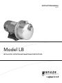
1
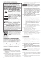
SAFETY INSTRUCTIONS
TO AVOID SERIOUS OR FATAL PERSONAL
INJURY OR MAJOR PROPERTY DAMAGE, READ
AND FOLLOW ALL SAFETY INSTRUCTIONS IN
MANUAL AND ON PUMP.
THIS MANUAL IS INTENDED TO ASSIST IN THE
INSTALLATION AND OPERATION OF THIS UNIT
AND MUST BE KEPT WITH THE PUMP.
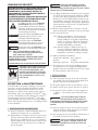
This is a SAFETY ALERT SYMBOL.
When you see this symbol on the pump
or in the manual, look for one of the
following signal words and be alert
to the potential for personal injury or
property damage.
DANGER Warns of hazards that WILL cause
serious personal injury, death or major
property damage.
WARNING Warns of hazards that CAN cause
serious personal injury, death or major
property damage.
Warns of hazards that CAN cause personal injury or property damage.
NOTICE: INDICATES SPECIAL INSTRUCTIONS WHICH ARE VERY IMPORTANT AND MUST BE FOLLOWED.
THOROUGHLY REVIEW ALL INSTRUCTIONS
AND WARNINGS PRIOR TO PERFORMING ANY
WORK ON THIS PUMP.
MAINTAIN ALL SAFETY DECALS.
CAUTION
WARNING
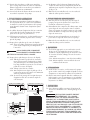
UNIT NOT DESIGNED FOR USE
WITH HAZARDOUS LIQUIDS OR
FLAMMABLE GASES. THESE
FLUIDS MAY BE PRESENT IN
CONTAINMENT AREAS.
Hazardous fluids
can cause fire,
burns or death.
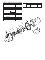
DESCRIPTION and SPECIFICATIONS:
The Model LB is a single stage, centrifugal jet pump for
general liquid transfer service and booster applications.
The liquid end utilizes a 304SS stamped casing, Noryl®
impeller, Lexan® ejector and guidevane, Amodel®
motor adapter and EPR o-rings. All motors are NEMA
48Y and 56Y square flange with a 304SS threaded shaft
extension.
1.3 Motors must be wired for proper voltage. Motor wiring diagram is on motor nameplate. Wire size must
limit maximum voltage drop to 10% of nameplate
voltage at motor terminals, or motor life and pump
performance will be lowered.
1.4 Always use horsepower-rated switches, contactor and
starters.
1.5 Motor protection
1.5.1 Single-phase: Thermal protection for singlephase units is sometimes built in (check nameplate). If no built-in protection is provided, use
a contactor with a proper overload. Fusing is
permissible.
1.5.2 Three-phase: Provide three-leg protection with
properly sized magnetic starter and thermal
overloads.
1.6 Maximum Operating Limits:
Liquid Temperature: 140ºF (60ºC)
Working Pressure:
Starts per Hour:
85 PSI
20, evenly distributed.
1.7 Regular inspection and maintenance will increase
service life. Base schedule on operating time. Refer
to Section 8.
2. INSTALLATION
2.1 Locate pump as near liquid source as possible (below
level of liquid for automatic operation).
2.2 Protect from freezing or flooding.
2.3 Allow adequate space for servicing and ventilation.
2.4 All piping must be supported independently of the
pump, and must “line-up” naturally.
NEVER DRAW PIPING IN PLACE BY
FORCING THE PUMP SUCTION AND
DISCHARGE CONNECTIONS.
CAUTION
2.5 Avoid unnecessary fittings. Select sizes to keep friction losses to a minimum.
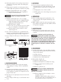
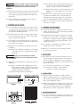
2.6 Units may be installed horizontally, inclined or vertically.
DO NOT INSTALL WITH MOTOR
BELOW PUMP. ANY LEAKAGE OR
CONDENSATION WILL AFFECT THE MOTOR.
CAUTION
1. IMPORTANT
1.1 Inspect unit for damage. Report any damage to carrier/dealer immediately.
1.2 Electrical supply must be a separate branch circuit
with fuses or circuit breakers, wire sizes, etc., in
compliance with National and Local electrical codes.
Install an all-leg disconnect switch near pump.
CAUTION
CONTROLS.
ALWAYS DISCONNECT ELECTRICAL
POWER WHEN HANDLING PUMP OR
2.7 Foundation must be flat and substantial to eliminate
strain when tightening bolts. Use rubber mounts to
minimize noise and vibration.
2.8 Tighten motor hold-down bolts before connecting
piping to pump.
3. SUCTION PIPING
3.1 Low static suction lift and short, direct, suction piping is desired. Consult pump performance curve for
Net Positive Suction Head Required.
3