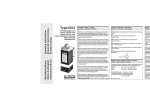
1
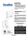
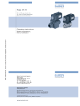
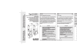
Type 6144 3/2-Wege Flipperventil 3/2-way Flipper Valve Èlectrovanne à languette 3/2 voies We reserve the right to make technical changes without notice. Technische Änderungen vorbehalten. Sous resérve de modification techniques. www.burkert.com Operating Instructions © 2007 - 2011 Bürkert Werke GmbH Bedienungsanleitung Manuel d‘utilisation Operating Instructions 1106/04_EU-ml_00805579 / Original: DE 1. THESE OPERATING INSTRUCTIONS The operating instructions contain important information. • Read the instructions carefully and follow the safety instructions in particular. • Keep the instructions in a location where they are available to every user. • The liability and warranty for Type 6144 are void if the operating instructions are not followed. 1.1. Definition of the Term "Device" In these instructions, the term"device" always refers to the Flipper Valve, Type 6144. 2. DEPICTIONS The following depictions are used in these instructions. DANGER! Warning of an immediate danger! • Failure to observe this warning will lead to death or serious injury. WARNING! Warning of a potentially hazardous situation! • Failure to observe this warning may lead to serious injury or death. CAUTION! Warning of a potential hazard! • Failure to observe this warning may lead to moderately serious or minor injuries. NOTE! Warning of damage to property! Important tips and recommendations. →→Indicates a job step that you have to perform. 2 english english 3 Type 6144 3. INTENDED PURPOSE 4. WARNING! Use of the Flipper Valve Type 6144 for other than its intended purpose may create hazards for persons, nearby equipment and the environment. • The device may not be used in outdoor locations. • Always observe the conditions for operations and use and the permissible data specified on the type plate and in the operating instructions. • Safe and correct operation is only possible with proper transport, storage and installation, and careful operation and maintenance. • Use the flipper value only for its intended purpose. 3.1. Foreseeable misuse • The flipper valve may be used in potentially explosive atmospheres only after approval has been granted. • Do not make any external modifications to the device housings. 3.2. Restrictions GENERAL SAFETY INSTRUCTIONS WARNING! Danger of injury from high pressure. • Before detaching lines and valves, cut off pressure and vent! Danger of burns/fire in continuous operation! In continuous operation the device may become very hot. • Any device that has been in operation for some time should only be touched with protective gloves. • Keep easily flammable materials and operating fluids away from the device. Installation and maintenance work may create hazardous situations. • Such work may only be performed by persons with the appropriate technical knowledge and using suitable tools! • After an interruption of the electricity or the compressed air supply, ensure that the process is started up again in a defined or controlled manner! Devices which are designed for use in zone 2/22: The user must ensure that this unit complies with the degree of protection IP54 in accordance with EN 60529. For example, by installing it in a suitable housing. 4 english WARNING! english 5. GENERAL INFORMATION Danger from unintentional activation of the system! 5.1. Contact address Unintentional start-up of the system may lead to injuries and property damage. • Use suitable means to prevent the system from being activated unintentionally. Germany CAUTION! Resource planning and operation of the device are subject to general engineering rules! Failure on your part to observe the rules may result in injuries and/or damage to the device, and possibly also to its surroundings. • Comply with general engineering rules! 5 Bürkert Fluid Control Systems Sales Center Chr.-Bürkert-Str. 13-17 D-74653 Ingelfingen Tel. : 07940 - 10 91 111 Fax: 07940 - 10 91 448 E-mail: [email protected] International For contact addresses, please see the last pages of these operating instructions. Also on the Internet at: www.burkert.com 4.1. Designs with explosion protection DANGER! Explosion hazard! Improper use in a potentially explosive atmosphere represents an explosion hazard. 5.2. Warranty The warranty is only valid if the device is used as authorized in accordance with the specified application conditions. 5.3. Information on the Internet Operating instructions and data sheets for Type 6144 are available on the Internet at: www.burkert.com 6 english english 7 Type 6144 6. STRUCTURE AND FUNCTION The Flipper Valve Type 6144 is a 3/2-way solenoid valve that can be operated either electrically (monostable or bistable) or mechanically via manual actuation. 7. Housing material Seal material PPS, fibreglass reinforced FKM 7.3. Type plate Example: WWC TECHNICAL DATA 7.1. Operating conditions Type WARNING! Circuit function Danger of injury due to function failure. Pressure range The device is not designed for use in outdoor locations. • Do not use the Type 6144 in outdoor locations, and avoid heat sources that could cause the temperature to exceed the permissible temperature range. Ambient temperature 0 to +55 °C Fluid temperature 0 to +55 °C Fluids Compressed air: oiled, oil-free or dry; neutral liquids and gases (5 µm filtering); Technical vacuum. Protection category IP40 with rectangular connector Protection class 3 acc. to VDE 0580 8 7.4. Pneumatic data Circuit functions 2 C 1 3 D see data sheet 1 3 3/2-way valve, direct acting, outlet 2 depressurized when deenergized 3/2-way valve, direct acting, outlet 2 pressurized when deenergized english english Fluid connections 1 P Pressure connection 2 A Working connection 3 R Exhaust air connection Pressure range see type plate Line connections Bürkert flange below Lateral flange at side MP01 flange at side (valve manifold) 7.5. Labelling of the electrical and fluid connections Polarity Electr. connection Housing symbol for determining position of the valve outlets on the underside of the housing: Serial no. 10 Voltage (±10 %) Order no. 2 7.2. Mechanical data Dimensions Power consumption english Arrangement of the value outlets 9 7.6. Electrical data Correct polarity is essential for the device to function! See chapter „7.5. Labelling of the electrical and fluid connections“ Operating voltage as per type plate ± 10 % Nominal power 0,8 W (see ATEX instructions for Explosion-proof version) Standard operating mode continuous operation, duty cycle 100% 7.6.1. Control of the bistable version: Labelling Polarity Min. pulse duration 50 ms Valve (P seat) is opened Valve (P seat) is closed Valve (P seat) is closed Valve (P seat) is opened english 11 Type 6144 8. ASSEMBLY 8.2. Fluid installations WARNING! 8.1. Safety instructions WARNING! Assembly work may result in hazardous situations. • Such work may only be performed by persons with appropriate technical knowledge and using suitable tools! • After an interruption of the electricity or the compressed air supply, ensure that the process is started up again in a defined or controlled manner! Danger from unintentional activation of the system! Danger of injury from high pressure. • Before detaching lines and valves, cut off pressure and vent! Risk of injury due to malfunction/escape of medium. If the exhaust air from other processes is used to generate compressed air for the device, the seals may be destroyed by the media contained in the air. • Use only fresh air to generate compressed air for the device. Unintentional start-up of the system may lead to injuries and property damage. • Use suitable means to prevent the system from being activated unintentionally. 8.1.1. D evices which are designed for use in zone 2/22 The user must ensure that this unit complies with the degree of protection IP54 in accordance with EN 60529. For example, by installing it in a suitable housing. Important operating conditions to avoid malfunctions: The valve must be at least 5 mm away from other ferromagnetic materials. Installation position:any, preferably with the drive upwards. Before assembly: →→Clean pipes and flange connections. →→To protect against malfunctions, install a filter (5 µm) upstream of the valve. 12 english english 13 Assembly of Type 6144 with Bürkert flange: (see Figure 1: Assembly drawing for Bürkert flange) WARNING! Valve with fastening elements Danger of escaping fluids! Connections will leak if the seal is not properly seated. • Ensure that the supplied sealing mat is correctly seated. Hole pattern: Sealing mat: →→Insert sealing mat into the valve. →→Assign fluids 1, 2 and 3 correctly on the valve and con- (see Figure 2: Assembly drawing for lateral flange) →→Assign fluids 1, 2 and 3 correctly on the valve and connection plate. →→Drill holes in accordance with hole pattern. →→Screw valve to connection plate →→Check valve for proper seal Fastening screws Hole pattern: M1.6 1 2 3 Fig. 2: 14 english ø 2.0 (max.) Assembly drawing for Bürkert flange ø 1.6 (max.) 5.5 Assembly of Type 6144 with lateral flange: Fig. 1: 4 3 2 1 21.5 Connection plate nection plate. →→Drill holes in accordance with hole pattern. →→Screw valve to connection plate →→Check valve for proper seal 4 M1.6 Valve with fastening elements Sealing mat: 6.4 Assembly drawing for lateral flange (FS09) english 15 Type 6144 Fig. 3: Manual actuation 8.2.1. Description of variants • The valve can be actuated manually via a hand lever. NOTE! The hand lever may be damaged if it is pressed and turned at the same time. • Do not press and turn the hand lever at the same time! • The location and function of the manual override and the position of the fluid connections vary depending on the design (see the following table). Description of the most important variants: Circuit Manual override Possible manual function next to port override lever function WWC Switching positions of the hand lever: Lock function: 90° rotation = maintained-contact switching WWD P Push & Lock R P Lock Lock R Push & Lock Normal position 8.3. Electrical installation Important instructions for proper functioning of the device: Push function: Pressing = brief actuation The device is designed for battery voltage. Do not use any technical DC voltage! Correct polarity is essential for the device to function! See chapter „7.5. Labelling of the electrical and fluid connections“. The push function is not available for all device variants (see table) 16 english english 9. 8.3.1. Electrical connection: 8.3.2. Observe voltage and type of current in accordance with type plate. Connection with direct current: 17 MAINTENANCE / MALFUNCTIONS NOTE! Damage caused by electrostatic charge! Standard version An electrostatic discharge may damage the device. with rectangular plug • Clean the device surface of the flipper valve by gently wiping it with a damp cloth. Under normal conditions, operation of the valve is maintenancefree. In the event of heavy external fouling, cleaning with suitable cleaning agents is recommended. If necessary, a test should be carried out to determine the suitability of the cleaning agent. Alternative electrical connections: Circular plug 2 Flying leads M8x1 9.1. Malfunctions 2 connector pins In the event of a malfunction, check the following: →→the line connections →→the operating pressure →→the voltage supply and valve actuation If the valve still does not operate, please contact your Bürkert service office. 18 english english 19 Type 6144 10. PACKAGING, TRANSPORT, STORAGE NOTE! Transport damages! Inadequately protected equipment may be damaged during transport. • During transportation protect the device against wet and dirt in shock-resistant packaging. • Avoid exceeding or dropping below the allowable storage temperature. Incorrect storage may damage the device. • Store the device in a dry and dust-free location! • Storage temperature. -20 ... +65 °C. 11. DISPOSAL NOTE! Damage to the environment caused by device components contaminated with media. • Dispose of the device and packaging in an environmentally friendly manner. • Observe applicable regulations on disposal and the environment. 20 english Typ 6144 3/2-Wege Flipperventil We reserve the right to make technical changes without notice. Technische Änderungen vorbehalten. Sous resérve de modification techniques. Bedienungsanleitung www.burkert.com © 2007 - 2011 Bürkert Werke GmbH Operating Instructions 1106/04_EU-ml_00805579 / Original: DE 1. DIE BEDIENUNGSANLEITUNG Die Bedienungsanleitung enthält wichtige Informationen. • Die Anleitung sorgfältig lesen und besonders die Hinweise zur Sicherheit beachten. • Die Anleitung so aufbewahren, dass sie jedem Benutzer zur Verfügung steht. • Die Haftung und Gewährleistung für Typ 6144 entfällt, wenn die Anweisungen der Bedienungsanleitung nicht beachtet werden. 1.1. Begriffsdefinition Gerät Der in dieser Anleitung verwendeten Begriff „Gerät“ steht immer für das Flipperventil Typ 6144. Deutsch 2. DARSTELLUNGSMITTEL In dieser Anleitung werden folgende Darstellungsmittel verwendet. GEFAHR! Warnt vor einer unmittelbaren Gefahr! • Bei Nichtbeachtung sind Tod oder schwere Verletzungen die Folge. WARNUNG! Warnt vor einer möglicherweise gefährlichen Situation! • Bei Nichtbeachtung können schwere Verletzungen oder Tod die Folge sein. VORSICHT! Warnt vor einer möglichen Gefährdung! • Nichtbeachtung kann mittelschwere oder leichte Verletzungen zur Folge haben. HINWEIS! Warnt vor Sachschäden! Wichtige Tipps und Empfehlungen. →→markiert einen Arbeitsschritt den Sie ausführen müssen. 22 deutsch deutsch 23 Typ 6144 3. BESTIMMUNGSGEMÄSSE VERWENDUNG WARNUNG! Bei nicht bestimmungsgemäßem Einsatz des Flipperventils Typ 6144 können Gefahren für Personen, Anlagen in der Umgebung und die Umwelt entstehen. • Das Gerät darf nicht im Außenbereich eingesetzt werden. • Für den Einsatz sind die in der Bedienungsanleitung und auf dem Typschild spezifizierten zulässigen Daten, sowie die Betriebs- und Einsatzbedingungen zu beachten. • Voraussetzungen für den sicheren und einwandfreien Betrieb sind sachgemäßer Transport, sachgemäße Lagerung und Installation sowie sorgfältige Bedienung und Instandhaltung. • Setzen Sie das Flipperventil nur bestimmungsgemäß ein. 3.2. Beschränkungen Geräte die für den Einsatz in Zone 2/22 konzipiert sind: Für die Schutzart IP54 nach EN 60529 dieser Einheit hat der Anwender sorge zu tragen. Beispielsweise durch den Einbau in ein geeignetes Gehäuse. 3.1. Vorhersehbarer Fehlgebrauch • Das Flipperventil darf nur entsprechend der Zulassung in explosionsgefährdeten Bereichen eingesetzt werden. • Nehmen Sie keine äußerlichen Veränderungen an den Gerätegehäusen vor. deutsch 24 4. GRUNDLEGENDE SICHERHEITSHINWEISE WARNUNG! Verletzungsgefahr durch hohen Druck. • Vor dem Lösen von Leitungen und Ventilen Druck abschalten und entlüften! Verbrennungsgefahr/Brandgefahr bei Dauerbetrieb! Das Gerät kann im Dauerbetrieb sehr heiß werden. • Ein Gerät das bereits länger in Betrieb ist nur mit Schutzhandschuhen anfassen. • Leicht brennbare Stoffe und Medien vom Gerät fernhalten. WARNUNG! Bei Installations- und Instandhaltungsarbeiten können Gefahrensituationen entstehen. • Diese Arbeiten dürfen nur durch Personen mit entsprechenden Fachkenntnissen und mit geeignetem Werkzeug durchgeführt werden! • Gewährleisten Sie nach einer Unterbrechung der elektrischen oder pneumatischen Versorgung einen definierten oder kontrollierten Wiederanlauf des Prozesses! 26 deutsch deutsch 25 WARNUNG! Gefahr durch unbeabsichtigte Betätigung der Anlage! Ungewolltes Ingangsetzen der Anlage kann zu Verletzungen und Sachschäden führen. • Verhindern Sie durch geeignete Maßnahmen, dass die Anlage unbeabsichtigt betätigt werden kann. VORSICHT! Für die Einsatzplanung und den Betrieb des Gerätes gelten die allgemeinen Regeln der Technik! • Beachten Sie die Regeln nicht, können Verletzungen entstehen und/oder das Gerät, ggf. auch dessen Umgebung, können beschädigt werden. • Halten Sie die allgemeinen Regeln der Technik ein! 4.1. Ausführungen mit Explosionsschutz GEFAHR! Explosionsgefahr! Bei unsachgemäßem Einsatz im explosionsgefährdeten Bereich besteht Explosionsgefahr. deutsch 27 Typ 6144 5. ALLGEMEINE HINWEISE 5.1. Kontaktadresse Deutschland Bürkert Fluid Control Systems Sales Center Chr.-Bürkert-Str. 13-17 D-74653 Ingelfingen Tel. : 07940 - 10 91 111 Fax: 07940 - 10 91 448 E-mail: [email protected] 6. AUFBAU UND FUNKTION Das Flipperventil Typ 6144 ist ein 3/2-Wege Magnetventil, das sowohl elektrisch (mono- oder bistabil) als auch mechanisch über eine Handbetätigung betrieben werden kann. International Die Kontaktadressen finden Sie auf den letzten Seiten dieser Bedienungsanleitung. Außerdem im Internet unter: www.burkert.com 5.2. Gewährleistung Voraussetzung für die Gewährleistung ist der bestimmungsgemäße Gebrauch des Flipperventils Typ 6144 unter Beachtung der spezifizierten Einsatzbedingungen. 5.3. Informationen im Internet Bedienungsanleitungen und Datenblätter zum Typ 6144 finden Sie im Internet unter: www.buerkert.de deutsch 28 7. TECHNISCHE DATEN 7.1. Betriebsbedingungen deutsch 29 7.3. Typschild Beispiel: WWC WARNUNG! Verletzungsgefahr durch Funktionsausfall. Typ Gerät ist nicht für den Einsatz im Außenbereich konzipiert. • Setzen Sie den Typ 6144 nicht im Außenbereich ein und vermeiden Sie Wärmequellen, die zur Überschreitung des zulässigen Temperaturbereichs führen können. Wirkungsweise Druckbereich Leistung Umgebungstemperatur 0 ... +55 °C Mediumstemperatur Schutzart Spannung (±10 %) 0 ... +55 °C Medien Druckluft geölt, ölfrei oder trocken; neutrale Flüssigkeiten und Gase (5 µm-Filterung); technisches Vakuum IP40 mit Rechteckstecker Bestell-Nr. 7.4. Pneumatische Daten Wirkungsweisen Schutzklasse 3 nach VDE 0580 7.2. Mechanische Daten Maße siehe Datenblatt Gehäusematerial PPS, glasfaservertärkt Dichtungsmaterial FKM 30 deutsch 2 C 1 3 2 D 1 3 3/2 Wege-Ventil, direktwirkend, stromlos Ausgang 2 entlastet 3/2-Wege-Ventil, direktwirkend, stromlos Ausgang 2 druckbeaufschlagt deutsch 31 Typ 6144 7.6. Elektrische Daten Fluidische Anschlüsse 1 P Druckanschluss 2 A Arbeitsanschluss 3 R Abluftanschluss Druckbereich Richtige Polarität ist Vorraussetzung für die Funktion des Gerätes! Siehe Kapitel „7.5. Kennzeichnung der elektrischen und fluidischen Anschlüsse“. siehe Typschild Leitungsanschlüsse Bürkert Flansch unten Winkelflansch seitlich MP01-Flansch seitlich (Ventilinsel) 7.5. Kennzeichnung der elektrischen und fluidischen Anschlüsse Betriebspannung entsprechend Typschild ± 10 % Nennleistung 0,8 W (siehe ATEX-Anleitung für Ex-Ausführung) Nennbetriebsart Dauerbetrieb, ED 100 % 7.6.1. Ansteuerung bistabile Ausführung: Polung Impulsdauer mind. 50 ms Polarität Elektr. Anschluss Kennzeichnung Gehäusesymbol zur Positionsbestimmung der Ventilausgänge an der Gehäuseunterseite: Serien-Nr. Ventil (P-Sitz) wird geschlossen Ventil (P-Sitz) wird geöffnet Anordung der Ventilausgänge deutsch 32 8. Ventil (P-Sitz) wird geöffnet Ventil (P-Sitz) wird geschlossen MONTAGE 8.1. Sicherheitshinweise WARNUNG! Bei Montagearbeiten können Gefahrensituationen entstehen. • Diese Arbeiten dürfen nur Personen mit entsprechenden Fachkenntnissen und mit geeignetem Werkzeug durchführen! • Gewährleisten Sie nach einer Unterbrechung der elektrischen oder pneumatischen Versorgung einen definierten oder kontrollierten Wiederanlauf des Prozesses! Gefahr durch unbeabsichtigte Betätigung der Anlage! Ungewolltes Ingangsetzen der Anlage kann zu Verletzungen und Sachschäden führen. • Verhindern Sie durch geeignete Maßnahmen, dass die Anlage unbeabsichtigt betätigt werden kann. 8.1.1. G eräte die für den Einsatz in Zone 2/22 konzipiert sind Für die Schutzart IP54 nach EN 60529 dieser Einheit hat der Anwender sorge zu tragen. Beispielsweise durch den Einbau in ein geeignetes Gehäuse. deutsch 33 8.2. Fluidische Installation WARNUNG! Verletzungsgefahr durch hohen Druck. • Vor dem Lösen von Leitungen und Ventilen Druck abschalten und entlüften! Verletzungsgefahr durch Funktionsausfall/ Mediumsaustritt. Wird zur Drucklufterzeugung für das Gerät die Abluft aus anderen Prozessen verwendet, können die Dichtungen durch die in der Luft enthaltenen Medien zerstört werden. • Zur Drucklufterzeugung für das Gerät nur Frischluft verwenden. Wichtige Betriebsbedingung zur Vermeidung von Fehlfunktionen: Das Ventil muss einen Mindestabstand von 5 mm zu anderen ferromagnetischen Materialien haben. Einbaulage: beliebig, vorzugsweise Antrieb nach oben. Vor der Montage: →→Rohrleitungen und Flanschanschlüsse von eventuellen Verschmutzungen säubern. →→Zum Schutz vor Störungen vor das Ventil einen Filter (5 µm) einbauen. 34 deutsch deutsch 35 Typ 6144 Montage Typ 6144 mit Bürkert-Flansch: (siehe Bild 1: Montagezeichnung für Bürkert-Flansch) WARNUNG! Ventil mit Befestigungselementen Gefahr durch Mediumsaustritt! Undichte Anschlüsse bei unkorrekt sitzender Dichtung. • Achten Sie auf den richtigen Sitz der mitgelieferten Dichtmatte. Bohrbild: Dichtmatte →→Dichtmatte in das Ventil einlegen. →→Fluidische Anschlussbelegung 1, 2 und 3 an Ventil und 4 M1,6 (siehe Bild 2: Montagezeichnung für Winkelflansch) →→Fluidische Anschlussbelegung 1, 2 und 3 an Ventil und Anschlussplatte richtig zuordnen. →→Bohrungen gemäß Bohrbild anbringen. →→Ventil auf Anschlussplatte schrauben →→Ventil auf Dichtheit prüfen. deutsch 36 Montagezeichnung für Bürkert-Flansch Befestigungsschrauben Ventil mit Befestigungselementen Bohrbild: ø 1,6 (max.) M1,6 1 2 3 Dichtmatte 5,5 Montage Typ 6144 mit Winkelflansch: Bild 1: ø 2,0 (max.) 3 2 1 21,5 Anschlussplatte Anschlussplatte richtig zuordnen. →→Bohrungen gemäß Bohrbild anbringen. →→Ventil auf Anschlussplatte schrauben →→Ventil auf Dichtheit prüfen. 4 6,4 Bild 2: Montagezeichnung für Winkelflansch (FS09) deutsch 37 8.2.1. Handbetätigung 8.2.2. Variantenbeschreibung • Das Ventil kann manuell über einen Handhebel betätigt werden. • Die Lage und Funktion der Handhebel sowie die Position der fluidischen Anschlüsse ist je nach Ausführung unterschiedlich (Siehe nachfolgende Tabelle). HINWEIS! Der Handhebel kann beschädigt werden, wenn er gedrückt und dabei gedreht wird. • Handhebel nicht gleichzeitig Drücken und Drehen! Schaltstellungen des Handhebels: Rastfunktion: 90° gedreht = einrastendes Umschalten Normalstellung Tastfunktion: Drücken = kurzzeitiges Betätigen Die Tastfunktion ist nicht bei allen Gerätevarianten verfügbar (siehe Tabelle) 38 deutsch Beschreibung der wichtigsten Varianten: Wirkungs- Lage des Handmögliche Handweisen hebels an hebelfunktion fluidischem Anschluss P Rasten & Tasten WWC R Rasten P Rasten WWD R Rasten & Tasten 8.3. Elektrische Installation Wichtiger Hinweis für die einwandfreie Funktion des Gerätes: Das Gerät ist für Batteriespannung ausgelegt. Keine technische Gleichspannung verwenden! Richtige Polarität ist Vorraussetzung für die Funktion des Gerätes! Siehe Kapitel „7.5. Kennzeichnung der elektrischen und fluidischen Anschlüsse“. deutsch 39 Typ 6144 9. 8.3.1. Elektrischer Anschluss: Spannung und Stromart laut Typschild beachten. Anschluss mit Gleichspannung: WARTUNG /STÖRUNGEN HINWEIS! Schäden durch elektrostatische Aufladung! Standardausführung Bei elektrostatischer Entladung kann das Gerät beschädigt werden. mit Rechteckstecker • Reinigen Sie die Geräteoberfläche des Flipperventils nur durch leichtes Abwischen mit einem feuchten Tuch. Das Ventil arbeitet unter Normalbedingungen wartungsfrei. Alternative Elektroanschlüsse: Zweipoliger Rund2 Einzellitzen stecker M8x1 Bei starker äußerer Verschmutzung wird eine Reinigung mit geeigneten Reinigungsmitteln empfohlen. Die Eignung des Reinigungsmittels sollte ggf. per Test ermittelt werden. 2 Steckerstifte 9.1. Störungen Überprüfen Sie bei Störungen →→die Leitungsanschlüsse →→den Betriebsdruck →→die Spannungsversorgung und Ventilansteuerung Falls das Ventil dennoch nicht schaltet, wenden Sie sich bitte an Ihren Bürkert-Service. 40 deutsch 10. VERPACKUNG, TRANSPORT, LAGERUNG HINWEIS! Transportschäden! Unzureichend geschützte Geräte können durch den Transport beschädigt werden. • Gerät vor Nässe und Schmutz geschützt in einer stoßfesten Verpackung transportieren. • Eine Über- bzw. Unterschreitung der zulässigen Lagertemperatur vermeiden. Falsche Lagerung kann Schäden am Gerät verursachen. • Gerät trocken und staubfrei lagern! • Lagertemperatur. -20 … +65 °C. 11. ENTSORGUNG HINWEIS! Umweltschäden durch von Medien kontaminierte Geräteteile. • Gerät und Verpackung umweltgerecht entsorgen! • Geltende Entsorgungsvorschriften und Umweltbestimmungen einhalten. 42 deutsch deutsch 41 Type 6144 Électrovanne à languette 3/2 voies We reserve the right to make technical changes without notice. Technische Änderungen vorbehalten. Sous resérve de modification techniques. Manuel d‘utilisation www.burkert.com © 2007 - 2011 Bürkert Werke GmbH Operating Instructions 1106/04_EU-ml_00805579 / Original: DE 1. INSTRUCTIONS DE SERVICE Le manuel d‘utilisation contiennent des informations importantes. • Lire attentivement le manuel et tenir particulièrement compte des consignes de sécurité. • Conserver le manuel d’utilisation afin qu’il soie accessible à tous les utilisateurs. • La responsabilité et la garantie légale concernant le type 6144 sont exclues en cas de non-respect des instructions de service. 1.1. Définition du terme appareil Le terme « appareil » utilisé dans ces instructions désigne toujours la Électrovanne à languette type 6144. Français 2. SYMBOLES GRAPHIQUES Plusieurs symboles graphiques sont utilisés dans les présentes instructions de service. DANGER ! Ce symbole met en garde contre un danger immédiat. • Le non respect de cette mise en garde peut entraîner des blessures graves, voire mortelles. AVERTISSEMENT ! Ce symbole met en garde contre une situation potentiellement dangereuse. • Le non respect de cette mise en garde peut entraîner des blessures graves, voire mortelles. ATTENTION ! Ce symbole met en garde contre un danger éventuel. • Le non respect de cette mise en garde peut entraîner des blessures légères ou moyennes. REMARQUE ! Met en garde contre des dommages matériels ! Désigne des informations supplémentaires importantes, des conseils et des recommandations. →→Opération devant être exécutée par l'utilisateur. 44 français français 45 Type 6144 3. UTILISATION CONFORME À LA DESTINATION AVERTISSEMENT ! L'utilisation non conforme de l’électrovanne à languette de type 6144 peut constituer un danger pour les personnes, les installations voisines et l'environnement. • L'appareil ne doit pas être installé et utilisé en plein air. • L'utilisation conforme de l'appareil inclut le respect des caractéristiques techniques spécifiées dans les instructions de service et sur la plaque signalétique, ainsi que le respect des conditions d'exploitation et de fonctionnement. • Elle suppose également de parfaites conditions de transport, de stockage et d'installation, ainsi qu'une utilisation et une maintenance soignées. • L’électrovanne à languette ne doit être exploitée que conformément à l'usage prévu. 3.2. Limitations Appareils conçus pour utilisation en zone 2/22 : L’utilisateur doit garantir le type de protection IP54 de l’unité selon EN 60529, par ex. par le montage dans un boîtier approprié. 3.1. Usage abusif prévisible • Pour pouvoir être utilisée dans une zone explosible, l’électrovanne à languette requiert une autorisation spécifique. • N'effectuer aucune transformation extérieure sur le boîtier de l'appareil. français 46 4. CONSIGNES DE SÉCURITÉ GÉNÉRALES AVERTISSEMENT ! Risque de blessure en raison d'une pression élevée. • Avant de desserrer les conduites et les électrovannes, coupez l'arrivée de pression et purgez l'appareil ! Risque de brûlure/d'incendie en cas d'exploitation en service continu ! Lorsqu'il est exploité en service continu, l'appareil peut devenir très chaud. • Avant de toucher un appareil en marche depuis un certain temps, enfilez des gants de protection. • Les matériaux et les fluides facilement inflammables doivent être tenus éloignés de l'appareil. Après une coupure de l’alimentation électrique ou pneumatique, exécutez une relance prédéfinie ou contrôlée du processus ! Risque en cas de mise en marche intempestive de l’installation ! La mise en marche indésirable de l’installation peut provoquer des blessures et des dommages matériels. • Vous devez mettre en œuvre des mesures adaptées pour empêcher que l’installation ne puisse être manœuvrée de façon indésirable. 48 français français 47 AVERTISSEMENT ! Les opérations d'installation et de maintenance peuvent être à l'origine de situations dangereuses. • Ces opérations doivent exclusivement être confiées à un personnel qualifié et réalisées à l'aide d'un outillage adapté ! ATTENTION ! Pour la planification d'emploi et l'exploitation de l'appareil, appliquez les règles de l'art communément reconnues ! La non application de ces règles peut entraîner des blessures corporelles et/ou des dommages au niveau de l'appareil et de son environnement. • Respectez les règles de l'art communément reconnues ! 4.1. Modèles avec protection antidéflagrante DANGER ! Risque d'explosion ! Il existe un risque de déflagration en cas d'utilisation non conforme de l'appareil dans une zone présentant un risque d'explosion. français 49 Type 6144 5. REMARQUES GÉNÉRALES 5.1. Adresse Allemagne Bürkert Fluid Control Systems, Sales Center Chr.-Bürkert-Str. 13-17 D-74653 Ingelfingen Tel. : 07940 - 10 91 111 Fax : 07940 - 10 91 448 E-mail : [email protected] 6. STRUCTURE ET FONCTIONNEMENT L’électrovanne à languette de type 6144 est une électrovanne à 3/2 voies dont l'actionnement peut être électrique (monostable ou bistable) ou mécanique (commande manuelle). International Les adresses des contacts internationaux figurent sur les dernières pages des présentes instructions de service. Nous sommes également présents sur Internet : www.burkert.com 5.2. Conditions de garantie La condition pour bénéficier de la garantie légale est l’utilisation conforme de l’appareil et le respect des conditions d’utilisation spécifiques. 5.3. Informations sur Internet Les instructions de service et les fiches techniques spécifiques aux appareils de type 6144 sont disponibles sur Internet : www.buerkert.fr français 50 7. CARACTÉRISTIQUES TECHNIQUES français 51 7.3. Plaque signalétique Exemple : WWC 7.1. Conditions d'exploitation AVERTISSEMENT ! Type Risque de blessure en cas de dysfonctionnement. Modes d‘action L'appareil n'est pas conçu pour être utilisé en plein air. • Ne pas installer l'appareil en plein air, le tenir éloigné des sources de chaleur car elles pourraient provoquer un dépassement de la plage de température autorisée. Température ambiante 0 ... +55 °C Température du fluide 0 ... +55 °C Plage de pression Puissance Tension (±10 %) FluidesAir comprimé avec huile, sans huile ou sec; Fluides et gaz neutres (filtrage 5 µm); Vide technique Type de protectionIP40 avec connecteur rectangulaire Classe de protection 3 selon VDE 0580 N° de cde 7.4. Caractéristiques pneumatiques Modes d'action 2 C 7.2. Caractéristiques mécaniques Dimensions cf. fiche technique Matériau du boîtier PPS, renforcé par fibres de verre Matériau d'étanchéité FKM 52 français 1 3 2 D 1 3 français Électrovanne à 3/2 voies, action directe, sortie 2 hors pression en l'absence de tension Électrovanne à 3/2 voies, action directe, sortie 2 sous pression en l'absence de tension 53 Type 6144 7.6. Caractéristiques électriques Raccords fluidiques 1 P Raccord de pression 2 A Raccord de travail 3 R Raccord d'échappement Plage de pression Le respect de la polarité électrique est une condition nécessaire au bon fonctionnement de l'appareil ! cf. plaque signalétique Raccords de conduitesbride Bürkert, en bas bride angulaire, sur le côté bride MP01, sur le côté (bloc de électrovannes) 7.5. Marquage des connexions électriques et fluidiques Voir chapitre „7.5. Marquage des connexions électriques et fluidiques“. Tension de fonctionnement cf. plaque signalétique ± 10% Puissance nominale 0,8 W (pour le modèle antidéflagrant: Certificat notice ATEX) Type de service nominal Service continu, ED 100 % Polarité Raccord électrique Symbole du boîtier pour la définition de la position des sorties de électrovanne sur la face inférieur du boîtier : N° de série français 54 8. Disposition des sorties de électrovanne MONTAGE Polarité Durée d'impulsion mini. 50 ms Marquage L’électrovanne (siège P) s'ouvre L’électrovanne (siège P) se ferme L’électrovanne L’électrovanne (siège P) se ferme (siège P) s'ouvre français 55 8.2. Installation fluidique 8.1. Consignes de sécurité AVERTISSEMENT ! Les opérations de montage peuvent être à l'origine de situations dangereuses. • Ces opérations doivent exclusivement être confiées à un personnel qualifié et réalisées à l'aide d'un outillage adapté ! Après une coupure de l'alimentation électrique ou pneumatique, exécutez une relance prédéfinie ou contrôlée du processus! Risque en cas de mise en marche intempestive de l'installation ! La mise en marche indésirable de l'installation peut provoquer des blessures et des dommages matériels. • Vous devez mettre en œuvre des mesures adaptées pour empêcher que l'installation ne puisse être manœuvrée de façon indésirable. 8.1.1. Appareils conçus pour utilisation en zone 2/22 L’utilisateur doit garantir le type de protection IP54 de l’unité selon EN 60529, par ex. par le montage dans un boîtier approprié. 56 7.6.1. Commande du modèle bistable : français AVERTISSEMENT ! Risque de blessure en raison d'une pression élevée. • Avant de desserrer les conduites et les électrovannes, coupez l'arrivée de pression et purgez l'appareil ! Risque de blessures dû à une panne/sortie de fluide. Si l’air d’échappement d’autres process est utilisé pour générer l’air comprimé, les fluides contenus dans l’air risquent de détruire les joints. • Utiliser uniquement de l’air frais pour générer l’air comprimé de l’appareil. Condition d'exploitation importante pour éviter tout dysfonctionnement : un écart minimal de 5 mm doit être maintenu entre l’électrovanne et tout autre matériau ferromagnétique. Position de montage :quelconque ; de préférence avec le mécanisme d'actionnement vers le haut. Avant le montage : →→nettoyer les tuyauteries et les raccords à bride afin d'éliminer d'éventuelles salissures. →→Monter un filtre (5 µm) pour protéger contre tout dysfonctionnement. français 57 Type 6144 Montage de l'appareil 6144 avec une bride Bürkert : (cf. figure 1 : schéma de montage pour bride Bürkert) AVERTISSEMENT ! Électrovanne avec éléments de fixation Danger en cas d'échappement de fluide ! Les joints mal positionnés menacent l'étanchéité des raccords. • Assurez-vous que les garnitures d'étanchéité fournies sont correctement installées. Schéma de perçage : Garniture d’étanchéité →→Introduire la garniture d'étanchéité dans l’électrovanne. →→Assigner correctement les raccords fluidiques 1, 2, 3 au Montage de l'appareil 6144 avec une bride angulaire : (cf. figure 2 : schéma de montage pour bride angulaire) →→Assigner correctement les raccords fluidiques 1, 2, 3 au niveau de l’électrovanne et de la plaque de raccordement. →→Présenter les trous conformément au schéma de perçage. →→Visser l’électrovanne sur la plaque de raccordement. →→Vérifier l'étanchéité de l’électrovanne. français 58 Fig. 1 : 4 ø 2,0 (max.) 3 2 1 21,5 Plaque de raccordement Schéma de montage pour bride Bürkert Vis de fixation Électrovanne avec éléments de fixation Schéma de perçage : ø 1,6 (max.) M1,6 1 2 3 Garniture d’étanchéité 5,5 niveau de l’électrovanne et de la plaque de raccordement. →→Présenter les trous conformément au schéma de perçage. →→Visser l’électrovanne sur la plaque de raccordement. →→Vérifier l'étanchéité de l’électrovanne. 4 M1,6 6,4 Fig. 2 : Schéma de montage pour bride angulaire (FS09) français 59 8.2.1. Actionnement manuel 8.2.2. Description des variantes • L’électrovanne peut être actionnée à l’aide d’une commande manuelle. • L'emplacement et le fonctionnement du levier manuel, ainsi que la position des raccords fluidiques, diffèrent en fonction du modèle d'appareil (cf. tableau ci-dessous). REMARQUE! La commande manuelle peut être endommagée si vous la tournez une fois enfoncée. • Ne pas enfoncer et tourner la commande manuelle simultanément. Positions de commutation de la commande manuelle : WWC WWD Fonction verrouillage : tournée de 90° = commutation dès l’enclenchement Position normale P R P R Touches et verrouillable verrouillable verrouillable Touches et verrouillable 8.3. Installation électrique Consigne importante pour le bon fonctionnement de l'appareil : Fonction à impulsion : Appui = commutation brève Fonction à impulsion n'est pas disponible sur toutes les variantes de l'appareil (cf. tableau). 60 Description des principales variantes : Modes Position du levier Fonction « levier d'action manuel au raccords manuel » possible fluidiques français L'appareil est conçu pour être alimenté par une batterie. N'utilisez aucune tension technique en courant continu ! Le respect de la polarité électrique est une condition nécessaire au bon fonctionnement de l’appareil ! Voir chapitre „7.5. Marquage des connexions électriques et fluidiques“. français 61 Type 6144 8.3.1. Raccordement électrique : 9. Respecter la tension et le type de courant indiqués sur la plaque signalétique. REMARQUE! Raccordement avec tension continue : ENTRETIEN / DÉPANNAGE Dommages dus à la charge électrostatique ! Modèle standard L’appareil peut être endommagé par une décharge électrostatique. avec connecteur rectangulaire • Nettoyez la surface de l’electrovanne à languette uniquement en essuyant légèrement avec un chiffon humide. Autres raccordements électriques : Connecteur rond 2 cordons simples 2 broches mâles à 2 pôles Dans des conditions de fonctionnement normales, l’électrovanne ne requiert aucun entretien. En cas d'encrassement extérieur important, il est conseillé de nettoyer l'appareil avec un détergent approprié. La qualification du détergent choisi doit être confirmée par un test. 9.1. Dépannage En cas d'incident, contrôler →→le raccordement des conduites →→la pression de fonctionnement →→l'alimentation en tension et la commande de l’électrovanne Si l’électrovanne continue de ne pas fonctionner, contacter le service après-vente de Bürkert. 62 français 10. EMBALLAGE, TRANSPORT, STOCKAGE REMARQUE ! Dommages dus au transport ! Les appareils insuffisamment protégés peuvent être endommagés pendant le transport. • Transportez l'appareil à l'abri de l'humidité et des impuretés et dans un emballage résistant aux chocs. • Évitez le dépassement vers le haut ou le bas de la température de stockage admissible. Un mauvais stockage peut endommager l'appareil. • Stockez l'appareil au sec et à l'abri des poussières ! • Température de stockage : -20 … +65 °C. 11. ELIMINATION REMARQUE! Dommages à l‘environnement causés par des pièces d‘appareil contaminées par des fluides. • Eliminez l‘appareil et l‘emballage dans le respect de l‘environnement. • Respectez les prescriptions en matière d‘élimination des déchets et de protection de l‘environnement en vigueur. 64 français français 63