1
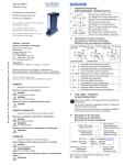
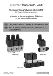
Type 6650
2/2 and 3/2-way flipper solenoid valve
2/2- und 3/2-Wege Flipper-Magnetventil
Electrovanne Flipper 2/2 ou 3/2
Operating Instructions
Bedienungsanleitung
Manuel d‘utilisation
1
Contents
OPERATING INSTRUCTIONS
The operating instructions contain important information.
▶▶ Read the instructions carefully and follow the safety instructions in
particular, and also observe the operating conditions.
▶▶ Instructions must be available to each user.
▶▶ The liability and warranty for Type 6650 are void if the operating
instructions are not followed.
1
Operating Instructions.............................................................................................................2
2
Intended use....................................................................................................................................3
3
Basic safety instructions.......................................................................................................4
4
Technical Data...............................................................................................................................5
5
Installation......................................................................................................................................11
6
Maintenance, Troubleshooting.......................................................................................13
1.1 Definition of term
7
Transport, Storage, Disposal............................................................................................14
The term “device” used in these instructions always stands for the
flipper solenoid valve type 6650.
english
2
1.2 Symbols
→→designates a procedure which you must carry out.
▶▶ Designates an instruction to prevent risks.
Warning of injuries:
DANGER!
Imminent danger. Serious or fatal injuries.
WARNING!
Potential danger. Serious or fatal injuries.
CAUTION!
Danger. Minor or moderately severe injuries.
Warns of damage to property:
NOTE!
Important tips and recommendations for safe and problem-free
operation of the device.
2
INTENDED USE
Incorrect use of the flipper solenoid valves type 6650 can be
dangerous to people, nearby equipment and the environment.
▶▶ The device is a media-separated solenoid valve and has been
designed for use in conjunction with gases and fluids (see Bürkert
Chemical Resistance Chart: www.burkert.com Typ 6650).
▶▶ Do not use the device outdoors without appropriate protective
measures.
▶▶ Use according to the permitted data, operating conditions and
conditions of use specified in the contract documents and operating instructions.
▶▶ The device is not intended for operation without suitable power
reduction electronics and must be operated only within the framework of the intended duty cycle.
▶▶ Only operate the device with suitable power reduction.
▶▶ Do not exceed the duty cycle (see Technical data).
▶▶ Only use in combination with external devices or components
which have been recommended or approved by Bürkert.
▶▶ Transport, store, install, operate and maintain the device correctly
as described in the operating instructions.
▶▶ Use the device only as intended.
english
3
2.1 Restrictions
If exporting the system/device, observe any existing restrictions.
3
BASIC SAFETY INSTRUCTIONS
These safety instructions do not make allowance for any contingencies and events which may arise during installation, operation and
maintenance.
Danger – high pressure.
▶▶ Before loosening the lines and valves, turn off the pressure and
vent the lines.
Risk of burns/risk of fire if used continuously through hot device
surface!
▶▶ Keep the device away from highly flammable substances and media
and do not touch with bare hands.
▶▶ Do not exceed the max. permitted duty cycle (see chapter “4.1 Operating Conditions”)
▶▶ Do not obstruct the heat dissipation that is required for the
operation.
General hazardous situations.
▶▶ The flipper solenoid valve type 6650 is not to be used in areas
where there is a risk of explosion.
▶▶ The connection clamps between coil and fluid housing must not be
removed under any circumstances.
▶▶ Do not make any internal or external changes to the device.
▶▶ Do not put any loads on the housing (e.g. by placing objects on it
or standing on it).
▶▶ Installation and repair work may be carried out by authorised technicians only.
▶▶ Ensure that the system cannot be activated unintentionally.
▶▶ After an interruption in the power supply or pneumatic supply,
ensure that the process is restarted in a defined or controlled
manner.
▶▶ The device may be operated only when in perfect condition and in
consideration of the operating instructions.
▶▶ The general rules of technology apply to application planning and
operation of the device.
english
4
4
NOTE!
Electrostatic sensitive components / modules.
The power reduction electronics, which is available as an accessory,
contains electronic components which react sensitively to electrostatic discharge (ESD). Contact with electrostatically charged
persons or objects is hazardous to these components. In the worst
case scenario, they will be destroyed immediately or will fail after
start-up.
• Observe the requirements in accordance with EN 61340-5-1 and
5-2 to minimize or avoid the possibility of damage caused by a sudden
electrostatic discharge.
• Do not touch live electronic components.
TECHNICAL DATA
4.1 Operating Conditions
WARNING!
Risk of injury
Malfunction if used outside!
▶▶ The valve must not be used outside without appropriate protective
measures.
▶▶ Avoid heat sources which may cause the permitted temperature
range to be exceeded.
Permitted temperatures
Ambient temperature:
Medium temperature:
+10...+50 °C
+15...+50 °C
Media: aggressive and neutral gaseous and liquid media according
to resistance
(see Bürkert Chemical Resistance Chart)
english
Max. duty cycle:50 s for block structure
60 s for single mounting
Longer duty cycle permitted with power reduction
electronics only
(see chapter “4.5 Electrical data”)
4.2 Mechanical data
(without electrical connector plug)
Add-on dimension 4.5 mm
Weight:
12.5 g
Degree of protection:IP65 to EN 60529
Dimensions:
4.5 x 38.5 x 41.2 mm
Protection class:
Housing material: PEEK
Sealing material:
FFKM
3 acc. to VDE 0580
WARNUNG!
Risk of injury due to leaking medium.
Connecting clamps might become loose when applying lateral, compressive or tensile force.
▶▶ Do not stress the device
mechanically.
▶▶ Do not apply lateral, compressive or tensile force to
Force F
Force F
the device.
Connecting clamps
6
english
5
4.3 Fluidic data
NC
IN
3/2-way universal
Circuit function T
*) DN =
Orifice
Example:
Orifice [DN]
Circuit
function
Sealing material
(CC=FFKM
FF = FKM)
Housing material
(PK=PEEK)
Made in Germany
Type
ΔP max. ***
IN
)
0,4
vak -7 bar
0,8
- **)
DN
NC
COM
NO
0,8
vak -1 bar
vak
1 bar
vak -1 bar 1 bar
DN
NC
COM
NO
ΔP max. ***)
0,8
- **)
vak 3 bar
- **)
3 bar
NC NO
NC NO
COM
6650 T 0,8 CC PK
24V-PWM vac-1bar
00189292
Voltage
Pressure range
Identification
number
vak -7 bar 7 bar
vak -3 bar 3 bar
COM
3/2-way distributor
Circuit function F
4.4 Label / Identification of connections
Made in Germany
**)Observe direction of flow.
Output pressure must
not be higher than input
pressure.
***)In vacuum mode observe
permitted differential
pressure.
DN*) NC
2/2-way NC
Circuit function A
Identification
of the fluid
connections
ΔP max. ***)
4.5 Electrical data
Connections:Type-specific plug-in connector, see data
sheet
Electrical power supply:12 V, 24 V
Voltage tolerance:
± 10 %
Power input: Start/activation impulse: 5.7 W
Holding power: 0.7 W
english
For the continuous operation of valve type 6650, a power reduction
electronics is required. It is recommended to use the electronics,
which is available as an accessory (see data sheet).
NOTE!
Malfunction due to overheating!
▶▶ The coil temperature must not exceed 110 ° C.
▶▶ If required, use suitable power reduction electronics.
▶▶ For a switch-on time > 50 s (for single mounting > 60 s) always use
a power reduction electronics!
▶▶ The electronics 670178, available as an accessory, are suitable for
a nominal voltage of 24 V only.
The following graphs provide a guideline for estimating whether a
power reduction electronics is required. If the gap between the individual units is < 10 mm, use the graph for the block structure. A power
reduction electronics is not required if the intersection point of switchon and switch-off time is in the upper area of the corresponding graph.
7
6
5
4
3
2
1
0
10
20
30
40
50
60
switch-on time [s]
0
0,5
1
1,5
2
2,5
3
switch-on time [s]
3,5
4
4,5
5
If the intersection point is on or below the plotted line or if the duty cycle
is longer than 60 seconds, power reduction electronics are essential.
In case the Bürkert electronics is not used, but another power
reduction electronics is implemented, the following parameters should
be applied:
in case of a PWM voltage drop:
Duty cycle 33 %, f=20kHz
Block structure
(Pulse / interval ratio at ambient temperature of 22 °C)
switch-off time [s]
400
350
300
250
200
150
100
50
0
0
Example: 40 s on - 100 s off
→ power reduction electronics required
english
8
switch-off time [s]
switch-off time [s]
4.5.1Continuos operation with power reduction
electronics
Single device
(Pulse / interval ratio at ambient temperature of 22 °C)
switch-off time [s]
The indicated values (power consumption) describe the heat
output. When designing the power supply, pay attention to appropriate reserves.
7
1200
1000
800
600
400
200
0
U
PWM-signal
20 kHz
switch-off point
100 %
0
60
5
10
15
20
25
30
35
40
switch-on time [s]
Example: 6 s on - 40 s off
→ power reduction electronics not required
45
50
50
0
5 ms
switch-on pulse
40
30
t
20
10
0
0
1
2
3
4
5
6
switch-on time [s]
7
8
9
10
If the intersection point is on or below the plotted line or if the duty cycle
is longer than 50 seconds, power reduction electronics are essential.
english
9
For OEM electronics (PWM) recommended circuit diagram:
for resistance reduction:
Switch-on pulse 100 % nominal voltage for 5 ms, then holding voltage 35
% nominal voltage
Circuit diagram for 24 V design
U
100 %
GND
GND
VDD
D5
1N4148
C3
100nF
GND
holding voltage
R2
41k
7
6
5
2
C2
470pF
GND
switch-off point
35 %
0
t
5 ms
Switch-on pulse
VDD
D3
1N4148
D4
1N4148
D2
BYM05-200
GND
VDD
R3
100k
C1
1uF
D1
ZMM5.1V
R4
330R
8 4
3
1
For OEM electronics (resistance reduction) recommended circuit
diagram:
TR1
IRLL2705
Circuit diagram for 24 V design
Connection
coil
R1
3k3 (24V)
1k2 (12V)
valve
supply voltage
VDD
TI1
TLC555
GND
GND
Caution : Drop approx. 1.6 W
Alternatively series or parallel connection of several resistors
english
10
5
INSTALLATION
5.2 Fluid Installation
DANGER!
5.1 Safety instructions
DANGER!
Danger – high pressure in the equipment.
▶▶ Before loosening the lines and valves, turn off the pressure and
vent the lines.
Danger – high pressure in the equipment.
▶▶ Before loosening the lines and valves, turn off the pressure and
vent the lines.
Installation position: any, actuator preferably upwards.
Procedure:
WARNING!
→→Before installation, clean any possible dirt off the pipelines and
Risk of injury from improper installation.
▶▶ Installation may be carried out by authorised technicians only and
with the appropriate tools!
Risk of injury from unintentional activation of the system and an
uncontrolled restart.
▶▶ Secure system from unintentional activation.
▶▶ Following installation, ensure a controlled restart.
flange connections.
→→Install a dirt trap to prevent malfunctions (Mesh size:
5 µm).
WARNING!
Danger through spillage of medium.
Leaking connections if seal seated incorrectly.
▶▶ Ensure that the supplied sealing gasket is seated correctly.
english
2-way normally closed:
max. ∅ 1.4
4.8
33
3-way universal function:
max. ∅ 1.4
4.8
33
M2
min. 6 deep
Flange screws
Recommended
torque:
0.35 Nm ± 0.1 Nm
Dimensional drawing for manifold:
M2
min. 6 deep
The add-on dimension must not fall short of 4.5 mm!
11
→→Check valve for leakage.
4.5
mm
Sealing gasket
Manifold
→→Insert the sealing gasket into the valve.
→→Correctly allocate the fluid connection configuration 1, 2 and 3 to
the valve and the manifold.
→→Screw valve onto the manifold.
12
english
5.3 Electrical Installation
NOTE!
Without proper power reduction electronics, the valve type 6650
is not suitable for continuous operation! Please refer to the
chapter titled “4.5 Electrical data”.
In the block structure all valves must be poled identically. The
mark (+) on the valve and the numerals 1 and 2 on the plug-in
connector are used as orientation. Example: On all units the
plug-in connector with numeral 2 points to the mark (+).
6
MAINTENANCE,
TROUBLESHOOTING
6.1 Safety instructions
plug-in connector
1 = brown
2 = white
If the power reduction electronics are used, observe the following polarity: brown + / white -.
A type-specific plug-in connector with or without integrated power
reduction electronics is available as an accessory (see data sheet).
DANGER!
Danger – high pressure in the equipment.
▶▶ Before loosening the lines and valves, turn off the pressure and
vent the lines.
WARNING!
Risk of injury from improper maintenance.
▶▶ Maintenance may be carried out by authorised technicians only and
with the appropriate tools.
Risk of injury from unintentional activation of the system and an
uncontrolled restart.
▶▶ Secure system from unintentional activation.
▶▶ Following maintenance, ensure a controlled restart.
english
6.2 Maintenance Work
7
The valve is maintenance-free under normal operating conditions.
NOTE!
If the exterior is very dirty, it is recommended to clean it with suitable
cleaning agents. If required, determine the suitability of the cleaning
agent by conducting a test.
WARNING!
Discharge of medium and malfunction if the connection clamps
are removed.
▶▶ The connection clamps between coil and fluid housing must not be
removed.
6.3 Malfunctions
If operating with power reduction electronics, ensure that the
power supply flank is quick enough.
If malfunctions occur, check
→→the line connections
→→the operating pressure
→→the power supply and valve control
TRANSPORT, STORAGE, DISPOSAL
Transport damages.
Inadequately protected equipment may be damaged during
transport.
▶▶ During transportation protect the device against wet and dirt in shockresistant packaging.
▶▶ Avoid exceeding or dropping below the permitted storage temperature.
Incorrect storage may damage the device.
▶▶ Store the device in a dry and dust-free location.
▶▶ Storage temperature: -10...65 °C.
Damage to the environment caused by device components
contaminated with media.
▶▶ Observe applicable regulations on disposal and the environment.
▶▶ Observe national waste disposal regulations.
If the valve still does not switch, please contact your Bürkert Service.
14
english
Bürkert Fluid Control Systems
Sales Center
Christian-Bürkert-Str. 13-17
D-74653 Ingelfingen
Tel. + 49 (0) 7940 - 10 91 111
Fax + 49 (0) 7940 - 10 91 448
E-mail: [email protected]
International address
www.burkert.com
Manuals and data sheets on the Internet: www.burkert.com
Bedienungsanleitungen und Datenblätter im Internet: www.buerkert.de
Manuels d'utilisation et fiches techniques sur Internet : www.buerkert.fr
© 2015 Bürkert Werke GmbH
Operating Instructions 1503/08_EU-ML_6650 / Original DE
www.burkert.com
13
Type 6650
2/2 and 3/2-way flipper solenoid valve
2/2- und 3/2-Wege Flipper-Magnetventil
Electrovanne Flipper 2/2 ou 3/2
Operating Instructions
Bedienungsanleitung
Manuel d‘utilisation
1
Inhaltsverzeichnis
DIE BEDIENUNGSANLEITUNG
Die Bedienungsanleitung enthält wichtige Informationen.
▶▶ Die Anleitung sorgfältig lesen und besonders die Hinweise zur
Sicherheit beachten.
▶▶ Die Anleitung so aufbewahren, dass sie jedem Benutzer zur Verfügung steht.
▶▶ Die Haftung und Gewährleistung für Typ 6650 entfällt, wenn die
Anweisungen der Bedienungsanleitung nicht beachtet werden.
1
Die Bedienungsanleitung..................................................................................................15
2
Bestimmungsgemäßer Gebrauch...............................................................................16
3
Grundlegende Sicherheitshinweise..........................................................................17
4
Technische Daten....................................................................................................................19
5
Installation......................................................................................................................................24
6
Wartung, Fehlerbehebung.................................................................................................27
1.1 Begriffsdefinition Gerät
7
Transport, Lagerung, Entsorgung................................................................................28
Der in dieser Anleitung verwendeten Begriff „Gerät“ steht immer für
den Typ 6650.
deutsch
1.2 Darstellungsmittel
→→markiert einen Arbeitsschritt den Sie ausführen müssen.
▶▶ markiert eine Anweisung zur Gefahrenvermeidung.
Warnung vor Verletzungen:
GEFAHR!
Unmittelbare Gefahr. Schwere oder tödliche Verletzungen.
WARNUNG!
Mögliche Gefahr. Schwere oder tödliche Verletzungen.
VORSICHT!
Gefahr. Mittelschwere oder leichte Verletzungen.
Warnung vor Sachschäden:
HINWEIS!
Wichtige Tipps und Empfehlungen für die Sicherheit und einwandfreie Funktion des Geräts.
16
deutsch
2
15
BESTIMMUNGSGEMÄSSER
GEBRAUCH
Bei nicht bestimmungsgemäßem Einsatz der Flipper-Magnetventile Typ 6650 können Gefahren für Personen, Anlagen in der
Umgebung und die Umwelt entstehen.
▶▶ Das Gerät ist ein mediengetrenntes Magnetventil und zum Einsatz
bei Gasen und Flüssigkeiten konzipiert (siehe Bürkert Beständigkeitstabelle: www.buerkert.de → Typ 6650).
▶▶ Für den Einsatz die in den Vertragsdokumenten und der Bedienungsanleitung spezifizierten zulässigen Daten, Betriebs- und
Einsatzbedingungen beachten.
Das Gerät
▶▶ Das Gerät nicht ohne passende Schutzvorkehrungen im Außenbereich einsetzen.
▶▶ Das Gerät nur mit geeigneter Leistungsabsenkung betreiben.
▶▶ Die Einschaltdauer nicht überschreiten (siehe Technische Daten).
▶▶ Nur in Verbindung mit von Bürkert empfohlenen bzw. zugelassenen
Fremdgeräten und -komponenten einsetzen.
▶▶ Nur in einwandfreiem Zustand betreiben und auf sachgerechte
Lagerung, Transport, Installation und Bedienung achten.
▶▶ Nur bestimmungsgemäß einsetzen.
3
2.1 Beschränkungen
Beachten Sie bei der Ausfuhr des Systems oder Geräts gegebenenfalls
bestehende Beschränkungen.
GRUNDLEGENDE
SICHERHEITSHINWEISE
Diese Sicherheitshinweise berücksichtigen keine Zufälligkeiten und
Ereignisse, die bei Montage, Betrieb und Wartung auftreten können.
Gefahr durch hohen Druck.
▶▶ Vor dem Lösen von Leitungen und Ventilen den Druck abschalten
und Leitungen entlüften.
Verbrennungsgefahr/Brandgefahr bei Dauerbetrieb durch heiße
Geräteoberfläche.
▶▶ Das Gerät von leicht brennbaren Stoffen und Medien fernhalten und
nicht mit bloßen Händen berühren.
▶▶ Die max. zulässige Einschaltdauer nicht überschreiten (siehe Kapitel
„4.1 Betriebsbedingungen“).
•Die für den Betrieb notwendige Wärmeabfuhr nicht behindern.
Allgemeine Gefahrensituationen
▶▶ Den Typ 6650 nicht in explosionsgefährdeten Bereichen
einsetzen.
deutsch
▶▶ Die Verbindungsklammern zwischen Spule und Fluidgehäuse dürfen unter keinen Umständen entfernt werden.
▶▶ Am Gerät keine inneren oder äußeren Veränderungen vornehmen.
▶▶ Das Gehäuse und die Spule nicht mechanisch belasten.
▶▶ Nur geschultes Fachpersonal darf Installations- und Instandhaltungsarbeiten ausführen.
▶▶ Darauf achten, dass die Anlage nicht unbeabsichtigt betätigt
werden kann.
▶▶ Nach einer Unterbrechung der elektrischen oder pneumatischen
Versorgung für einen definierten oder kontrollierten Wiederanlauf
des Prozesses sorgen.
▶▶ Das Gerät nur in einwandfreiem Zustand und unter Beachtung der
Bedienungsanleitung betreiben.
▶▶ Für die Einsatzplanung und den Betrieb des Geräts die allgemeinen Regeln der Technik einhalten.
HINWEIS!
Elektrostatisch gefährdete Bauelemente / Baugruppen.
Das Gerät enthält elektronische Bauelemente, die gegen elektrostatische Entladung (ESD) empfindlich reagieren. Berührung mit elektrostatisch aufgeladenen Personen oder Gegenständen gefährdet
diese Bauelemente. Im schlimmsten Fall werden sie sofort zerstört
oder fallen nach der Inbetriebnahme aus.
•Die Anforderungen nach EN 61340-5-1 beachten, um die Möglichkeit eines Schadens durch schlagartige elektrostatische Entladung zu minimieren bzw. zu vermeiden!
• Elektronische Bauelemente nicht bei anliegender Versorgungsspannung berühren!
deutsch
18
4
17
TECHNISCHE DATEN
4.1 Betriebsbedingungen
WARNUNG!
Verletzungsgefahr
Funktionsausfall bei Einsatz im Außenbereich!
▶▶ Das Ventil darf nicht ohne passende Schutzvorkehrungen im
Außenbereich eingesetzt werden.
▶▶ Wärmequellen vermeiden, die zur Überschreitung des zulässigen
Temperaturbereichs führen können.
Zulässige Temperaturen
Umgebungstemperatur: +10...+50 °C
Mediumstemperatur: +15...+50 °C
Medien: aggressive, neutrale gasförmige und flüssige
Medien entsprechend Beständigkeit (siehe Bürkert
Beständigkeitstabelle)
Längere Einschaltdauer nur mit Leistungsabsenkung zulässig (siehe
Kapitel „4.5 Elektrische Daten“)
Schutzart:
IP65 nach EN 60529
Schutzklasse:3 nach VDE 0580
WARNUNG!
Verletzungsgefahr durch Mediumsaustritt.
Seitliche Krafteinwirkung, Druck- oder Zugkraft, kann zum Lösen der
Verbindungsklammern führen.
▶▶ Gerät darf nicht mechanisch
belastet werden.
▶▶ Keine seitliche Krafteinwirkung, Druck- oder Zugkraft,
Kraft F
Kraft F
auf das Gerät ausüben.
Verbindungsklammern
Max. Einschaltdauer: 5
0 s bei Blockaufbau
60 s bei Einzelmontage
deutsch
19
4.2 Mechanische Daten
4.3 Fluidische Daten
(ohne elektrischen Stecker)
**)Durchflussrichtung
beachten. Ausgangsdruck
darf nicht höher sein als
Eingangsdruck.
***)Bei Vakuumbetrieb
zulässigen Differenzdruck
beachten.
Anreihmaß:
4,5 mm
Gewicht:
12,5 g
Maße:
4,5 x 38,5 x 41,2 mm
Gehäusematerial: PEEK
*) DN =
Nennweite
DN*)
NC
IN
ΔP max. ***)
NC
0,4
vak -7 bar
vak -7 bar
7 bar
IN
0,8
- **)
DN
NC
0,8
vak -1 bar
DN
NC
COM
NO
ΔP max. ***)
0,8
- **)
vak 3 bar
- **)
3 bar
2/2-Wege NC
Wirkungsweise A
Dichtungsmaterial:FFKM
Made in Germany
3/2-Wege Universal
Wirkungsweise T
COM
NC NO
3/2-Wege Verteiler
Wirkungsweise F
NC NO
COM
vak -3 bar
3 bar
NO
ΔP max. ***)
COM
vak
vak -1 bar
1 bar
1 bar
deutsch
20
4.4 Typschild / Anschlusskennzeichung
Beispiel:
Nennweite [DN]
Made in Germany
Typ,
Wirkungsweise
6650 T 0,8 CC PK
24V-PWM vac-1bar
00189292
Dichtungsmaterial
(CC=FFKM
FF = FKM)
Gehäusematerial
(PK=PEEK)
Kennzeichnung
der fluidischen
Anschlüsse
Identnummer
4.5 Elektrische Daten
Anschlüsse:typspezifischer Steckverbinder, siehe
Datenblatt
Spannungsversorgung:12 V, 24 V
Spannungstoleranz:
Für den kontinuierlichen Betrieb des Ventils Typ 6650 ist eine Leistungsabsenkung erforderlich. Es wird empfohlen, die als Zubehör
erhältliche Elektronik zu verwenden (siehe Datenblatt).
HINWEIS!
Druckbereich
Spannung
4.5.1Kontinuierlicher Betrieb mit
Leistungsabsenkung
± 10 %
Leistungsaufnahme: Anzugs-/Einschaltimpuls: 5,7 W
Halteleistung: 0,7 W
Die angegebenen Werte (Leistungsaufnahme) beschreiben die
Warmleistung. Bei der Auslegung der Stromversorgung auf entsprechende Reserven achten.
Funktionsausfall durch Überhitzung.
▶▶ Die Spulentemperatur darf 110 °C nicht überschreiten.
▶▶ Wenn erforderlich, geeignete Leistungsabsenkung verwenden.
▶▶ Für eine Einschaltzeit > 50 s (bei Einzelmontage > 60 s) ist immer
eine Leistungsabsenkung zu verwenden!
▶▶ Die als Zubehör lieferbare Elektronik 670178 ist nur für Nennspannung 24 V geeignet.
Nachfolgende Diagramme bieten eine Richtlinie, um die Notwendigkeit
einer Leistungsabsenkung abschätzen zu können. Bei einem Abstand
der Einzelgeräte < 10 mm ist das Diagramm für den Blockaufbau
zugrunde zu legen. Keine Leistungsabsenkung ist notwendig, wenn der
Schnittpunkt von Ein- und Ausschaltzeit im oberen Bereich des entsprechenden Diagramms liegt.
deutsch
7
6
5
4
3
2
1
0
Beispiel: 40 s ein - 100 s aus
→ Leistungsabsenkungselektronik erforderlich
10
20
30
Einschaltzeit [s]
Ausschaltzeit [s]
400
350
300
250
200
150
100
50
0
0
Blockaufbau
(Impuls-/Pausenverhältnis bei 22 °C Umgebungstemperatur)
40
50
0
5
10
15
20
25
30
35
40
45
Einschaltzeit [s]
Beispiel: 6 s ein - 40 s aus
→ k eine Leistungsabsenkungselektronik erforderlich
50
0
1
2
3
10
60
0
0,5
1
1,5
2
2,5
3
Einschaltzeit [s]
3,5
4
4,5
5
Liegt der Schnittpunkt auf oder unterhalb der eingezeichneten Linie oder
ist die Einschaltzeit länger als 60 Sekunden ist eine Leistungsabsenkung
zwingend erforderlich.
22
1200
1000
800
600
400
200
0
60
Ausschaltzeit [s]
Ausschaltzeit [s]
Ausschaltzeit [s]
Einzelgerät
(Impuls-/Pausenverhältnis bei 22 °C Umgebungstemperatur)
21
deutsch
50
40
30
20
10
0
4
5
6
Einschaltzeit [s]
7
8
9
Liegt der Schnittpunkt auf oder unterhalb der eingezeichneten Linie oder
ist die Einschaltzeit länger als 50 Sekunden ist eine Leistungsabsenkung
zwingend erforderlich.
PWM-Signal
20 kHz
Abschaltpunkt
100 %
VDD
R1
3k3 (24V)
1k2 (12V)
GND
GND
VDD
0
5 ms
Einschaltimpuls
D5
1N4148
t
C3
100nF
VDD
R2
41k
D3
1N4148
D4
1N4148
GND
D2
BYM05-200
GND
VDD
R3
100k
C1
1uF
D1
ZMM5.1V
C2
470pF
7
6
5
2
GND
R4
330R
8 4
3
1
TR1
IRLL2705
TI1
TLC555
GND
GND
deutsch
5
•bei Widerstandsabsenkung,
Einschaltimpuls 100 % Nennspannung für 5 ms, danach Haltespannung 35 % Nennspannung.
Ventil
U
Für OEM-Elektroniken (PWM) empfohlener Schaltplan:
Schaltplan für 24 V Auslegung
Versorgungsspannung
Wird die Bürkert Elektronik nicht verwendet, aber dennoch eine Leistungsabsenkung eingesetzt, sind folgende Parameter zu verwenden:
•bei PWM Spannungsabsenkung,
Tastgrad 33 %, f = 20 kHz.
23
INSTALLATION
5.1 Sicherheitshinweise
U
100 %
GEFAHR!
Haltespannung
35 %
Verletzungsgefahr durch hohen Druck in der Anlage.
▶▶ Vor dem Lösen von Leitungen und Ventilen den Druck abschalten
und Leitungen entlüften.
Abschaltpunkt
0
t
5 ms
Einschaltimpuls
Für OEM-Elektroniken (Widerstandsabsenkung) empfohlener Schaltplan:
Anschluss
Spule
Schaltplan für 24 V Auslegung
WARNUNG!
Verletzungsgefahr bei unsachgemäßer Installation.
▶▶ Die Installation darf nur autorisiertes Fachpersonal mit geeignetem
Werkzeug durchführen.
Verletzungsgefahr durch ungewolltes Einschalten der Anlage
und unkontrollierten Wiederanlauf.
▶▶ Anlage vor unbeabsichtigtem Betätigen sichern.
▶▶ Nach der Installation einen kontrollierten Wiederanlauf
gewährleisten.
Achtung: Leistungsaufnahme ca. 1,6 W
Alternativ Reihen- oder Parallelschaltung mehrerer Widerstände
deutsch
24
5.2 Fluidische Installation
GEFAHR!
Das Anreihmaß von 4,5 mm darf nicht unterschritten werden.
Verletzungsgefahr durch hohen Druck in der Anlage.
▶▶ Vor dem Lösen von Leitungen und Ventilen den Druck abschalten
und Leitungen entlüften.
Flanschschrauben
Empfohlenes
Anziehdrehmoment:
0,35 Nm ± 0,1 Nm
Einbaulage: beliebig, vorzugsweise Antrieb nach oben.
Vorgehensweise:
→→Vor der Montage Rohrleitungen und Flanschanschlüsse von
eventuellen Verschmutzungen säubern.
→→Zum Schutz vor Störungen einen Schmutzfänger einbauen
(Maschenweite: 5 µm).
4,5
Dichtmatte
Anschlussplatte
WARNUNG!
Gefahr durch Mediumsaustritt.
Undichte Anschlüsse bei unkorrekt sitzender Dichtung.
▶▶ Achten Sie auf den richtigen Sitz der mitgelieferten Dichtmatte.
mm
→→Dichtmatte in das Ventil einlegen.
→→Fluidische Anschlussbelegung 1, 2 und 3 an Ventil und
Anschlussplatte richtig zuordnen.
→→Ventil auf Anschlussplatte schrauben.
deutsch
25
Maßzeichnung für Anschlussplatte:
max. ∅ 1,4
max. ∅ 1,4
4,8
33
4,8
33
M2
min. 6 tief
3-Wege-Ausführung:
M2
min. 6 tief
2-Wege-Ausführung:
→→Ventil auf Dichtheit prüfen.
Steckverbinder
1 = braun
2 = weiß
Bei Verwendung der Leistungabsenkungselektronik ist folgende Polarität zu beachten: braun + / weiß –.
5.3 Elektrische Installation
HINWEIS!
Das Ventil Typ 6650 ist ohne eine bestimmungsgemäße Leistungsabsenkung nicht für den Dauerbetrieb geeignet. Siehe
Kapitel „4.5 Elektrische Daten“.
Ein typspezifischer Steckverbinder ist als Zubehör (siehe Datenblatt)
sowohl mit als auch ohne integrierte Leistungsabsenkungselektronik
erhältlich.
Im Blockaufbau müssen alle Ventile gleich gepolt sein. Als
Orientierung dient die Markierung (+) am Ventil und die Ziffern
1 und 2 auf dem Steckverbinder. Beispiel: Bei allen Geräten
zeigt der Steckverbinder mit der Ziffer 2 zur Markierung (+).
deutsch
26
6
WARTUNG, FEHLERBEHEBUNG
6.1 Sicherheitshinweise
GEFAHR!
Verletzungsgefahr durch hohen Druck in der Anlage.
▶▶ Vor dem Lösen von Leitungen und Ventilen den Druck abschalten
und Leitungen entlüften.
WARNUNG!
Verletzungsgefahr bei unsachgemäßen Wartungsarbeiten.
▶▶ Die Wartung darf nur autorisiertes Fachpersonal mit geeignetem
Werkzeug durchführen.
Verletzungsgefahr durch ungewolltes Einschalten der Anlage
und unkontrollierten Wiederanlauf.
▶▶ Anlage vor unbeabsichtigtem Betätigen sichern.
▶▶ Nach der Wartung einen kontrollierten Wiederanlauf
gewährleisten.
6.2 Wartungsarbeiten
Das Ventil arbeitet unter Normalbedingungen wartungsfrei.
Bei starker äußerer Verschmutzung wird eine Reinigung mit geeigneten Reinigungsmitteln empfohlen. Die Eignung des Reinigungsmittels sollte gegebenenfalls per Test ermittelt werden.
WARNUNG!
Mediumsaustritt und Fehlfunktion bei Entfernen der
Verbindungsklammern.
▶▶ Die Verbindungsklammern zwischen Spule und Fluidgehäuse
dürfen nicht entfernt werden.
6.3 Störungen
Bei Betrieb mit Leistungsabsenkungselektronik darauf achten,
dass die Flanke der Versorgungsspannung genügend schnell
ist.
Überprüfen Sie bei Störungen
→→die Leitungsanschlüsse,
→→den Betriebsdruck,
→→die Spannungsversorgung und Ventilansteuerung.
deutsch
Falls das Ventil dennoch nicht schaltet, wenden Sie sich bitte an Ihren
Bürkert-Service.
7
TRANSPORT, LAGERUNG,
ENTSORGUNG
HINWEIS!
Transportschäden.
Unzureichend geschützte Geräte können durch den Transport
beschädigt werden.
▶▶ Gerät vor Nässe und Schmutz geschützt in einer stoßfesten Verpackung transportieren.
▶▶ Eine Über- bzw. Unterschreitung der zulässigen Lagertemperatur
vermeiden.
Falsche Lagerung kann Schäden am Gerät verursachen.
▶▶ Gerät trocken und staubfrei lagern.
▶▶ Lagertemperatur –10…+65 °C.
28
deutsch
Umweltschäden durch von Medien kontaminierte Teile.
▶▶ Gerät und Verpackung umweltgerecht entsorgen.
▶▶ Geltende Entsorgungsvorschriften und Umweltbestimmungen
einhalten.
27
Bürkert Fluid Control Systems
Sales Center
Christian-Bürkert-Str. 13-17
D-74653 Ingelfingen
Tel. + 49 (0) 7940 - 10 91 111
Fax + 49 (0) 7940 - 10 91 448
E-mail: [email protected]
International address
www.burkert.com
Manuals and data sheets on the Internet: www.burkert.com
Bedienungsanleitungen und Datenblätter im Internet: www.buerkert.de
Manuels d'utilisation et fiches techniques sur Internet : www.buerkert.fr
© 2015 Bürkert Werke GmbH
Operating Instructions 1503/08_EU-ML_6650 / Original DE
www.burkert.com
Type 6650
2/2 and 3/2-way flipper solenoid valve
2/2- und 3/2-Wege Flipper-Magnetventil
Electrovanne Flipper 2/2 ou 3/2
Operating Instructions
Bedienungsanleitung
Manuel d‘utilisation
1
Sommaire
1
Manuel d’utilisation..................................................................................................................29
2
Utilisation conforme...............................................................................................................30
3
Consignes de sécurité fondamentales...................................................................31
4
Caractéristiques techniques............................................................................................33
5
Installation......................................................................................................................................38
6
Maintenance, dépannage..................................................................................................41
7
Transport, Stockage, Elimination..................................................................................42
MANUEL D’UTILISATION
Manuel d’utilisation contiennent des informations importantes.
▶▶ Lire attentivement ce manuel et respecter les consignes de sécurité.
▶▶ Le manuel doit être à disposition de chaque utilisateur.
▶▶ Nous déclinons toute responsabilité et n’accordons aucune garantie
légale pour le type 6650 en cas de non-respect des instructions figurant
dans ce manuel d’utilisation.
1.1 Définition du terme
Le terme « appareil» utilisé dans ce manuel désigne toujours l’électrovanne type 6650.
français
1.2 SYMBOLES
→→identifie une opération que vous effectuer.
▶▶ Identifie une instruction visant à éviter un danger.
Mise en garde contre les blessures :
DANGER!
Danger imminent. Les blessures graves ou mortelles.
AVERTISSEMENT!
Danger possible. Les blessures graves ou mortelles.
ATTENTION!
Danger. Les blessures légères ou moyennement graves.
Met en garde contre des dommages matériels:
REMARQUE!
Conseils et recommandations importants pour la sécurité et le
parfait fonctionnement de l’appareil.
30
29
2
UTILISATION CONFORME
L’utilisation non conforme des vannes magnétiques Flipper de
type 6650 peut présenter des dangers pour les personnes, les
installations proches et l’environnement.
▶▶ L'appareil est une électrovanne avec séparation des fluides destinées
aux gaz et aux liquides (voir « Résistances chimique « Bürkert: www.
burkert.fr Typ 6650).
▶▶ N'utilisez pas l'appareil à l'extérieur sans mesures de protection
adaptées.
▶▶ Lors de l'utilisation, il convient de respecter les données et conditions d'utilisation et d'exploitation admissibles spécifiées dans le
manuel d’utilisation et dans les documents contractuels.
▶▶ L'appareil n'est pas destiné au fonctionnement sans une baisse de
puissance adaptée, ou doit uniquement être exploité dans le cadre
de la durée d'enclenchement conforme.
▶▶ L’appareil ne doit fonctionner qu’avec une réduction de puissance
appropriée.
▶▶ Ne pas dépasser la durée de mise en marche (voir Caractéristiques techniques).
français
▶▶ Utiliser uniquement en association avec des appareils et composants externes recommandés ou agréés par Bürkert.
▶▶ Transporter, stocker, installer, manœuvrer et entretenir l‘appareil de
manière appropriée comme décrit dans le mode d‘emploi.
▶▶ Veillez à ce que l’utilisation de l’appareil soit toujours conforme.
2.1 Limitations
Lors de l’exportation du système/de l’appareil, veuillez respecter les
limitations éventuelles existantes.
3
CONSIGNES DE SÉCURITÉ
FONDAMENTALES
Ces consignes de sécurité ne tiennent pas compte des hasards et des événements pouvant survenir lors du montage, de l’exploitation et de l’entretien.
AVERTISSEMENT!
Danger dû à la haute pression.
▶▶ Avant de desserrer les conduites et les vannes, coupez la pression
et purgez l’air des conduites.
Risque de brûlures/d’incendie en fonctionnement continu dû à
des surfaces d’appareils brûlantes.
▶▶ Tenez les substances et les fluides facilement inflammables à l’écart
de l’appareil et ne touchez pas ce dernier à mains nues.
▶▶ Ne pas dépasser la durée d‘enclenchement max. admissible (voir
chapitre « 4.1 Conditions d’exploitation »)
▶▶ Ne pas gêner l’évacuation de la chaleur nécessaire au
fonctionnement.
français
Situations dangereuses d’ordre général.
▶▶ La électrovanne Flipper type 6650 ne doit pas être utilisée dans
des zones présentant des risques d’explosion.
▶▶ Les brides de raccordement entre la bobine et le boîtier fluidique
ne doivent en aucun cas être retirées.
▶▶ Ne pas apporter de modifications intérieures ou extérieures à
l‘appareil.
▶▶ Ne pas exposer le corps et la bobine à des sollicitations
mécaniques.
▶▶ Les travaux d’installation et de maintenance doivent être effectués
uniquement par des techniciens qualifiés et habilités disposant de
l’outillage approprié.
▶▶ Veiller à ce que l‘installation ne puisse pas être actionnée de
manière intempestive.
▶▶ Après une interruption de l’alimentation électrique ou pneumatique,
un redémarrage défini ou contrôlé du processus doit être garanti.
▶▶ L’appareil doit être utilisé uniquement en parfait état et en respectant le manuel d’utilisation.
▶▶ Les règles générales de la technique sont d’application pour planifier l’utilisation et utiliser l’appareil.
REMARQUE !
Eléments/sous-groupes sujets aux risques électrostatiques.
L'électronique de baisse de puissance disponible sous forme
d'accessoire contient des éléments électroniques sensibles aux
décharges électrostatiques (ESD). Ces éléments sont affectés par
le contact avec des personnes ou des objets ayant une charge
électrostatique. Au pire, ils sont immédiatement détruits ou tombent
en panne après mise en service.
• Respecter les exigences selon EN 61340-5-1 et 5-2 afin de minimiser ou éviter le risque d‘un dommage par une décharge électrostatique brusque.
• Ne pas toucher les composants électroniques lorsque la tension
d‘alimentation est présente.
français
32
4
31
CARACTÉRISTIQUES TECHNIQUES
Une durée d‘enclenchement plus longue
est uniquement admissible moyennant une
baisse de puissance (voir chapitre « 4.5
Caractéristiques électriques »)
4.1 Conditions d’exploitation
AVERTISSEMENT !
Risque de blessures
Panne lors de l'utilisation à l'extérieur.
▶▶ La vanne ne doit pas être utilisée à l'extérieur sans les mesures de
protection adaptées.
▶▶ Eviter les sources de chaleur pouvant entraîner le dépassement de
la plage de température admissible.
Températures admissibles
Température ambiante : +10...+50 °C
Température du fluide : +15...+50 °C
Fluides : Fluides liquides et gazeux, agressifs et neutres, conformément à la résistance (voir « Résistances chimique «
Bürkert)
Degré de protection :
IP65 selon EN 60529
Classe de protection : 3 selon VDE 0580
AVERTISSEMENT!
Risque de blessure dû à la sortie de fluide.
Une force latérale, une force de traction ou de pression peut entraîner
le détachement des agrafes de liaison.
▶▶ Ne pas exposer l’appareil à
une sollicitation mécanique.
▶▶ Ne pas exercer de force latérale, de force de traction ou
Force F
Force F
de pression sur l’appareil.
agrafes de liaison
Durée
d‘enclenchement max. :50 s pour une structure en bloc
60 s pour un montage individuel
français
33
4.2 Caractéristiques mécaniques
4.3 Données fluidiques
(sans connecteur électrique)
* DN = Diamètre nomina
**)Respecter le sens
d‘écoule-ment. La
pression de sortie ne
peut pas être plus
élevée que la pression
d‘entrée.
Made in Germany
***)En cas de
fonctionnement sous
vide, tenir
compte de
la différence
de pression
)
Cote de jonction 4,5 mm
Poids :
12,5 g
Dimensions :
4,5 x 38,5 x 41,2 mm
Matériau du boîtier : PEEK
DN
*)
2/2 voies NC
Fonction A
Matériau du joint :FFKM
NC
NC
0,4 vak -7 bar
IN
0,8
- **)
DN
NC
3/2 voies universel
Fonction T
COM
ΔP max. ***)
vak -7 bar
7 bar
vak -3 bar
3 bar
NO
ΔP max. ***)
0,8 vak -1 bar
vak 1
vak -1 bar
bar
DN
NC
COM
NO
ΔP max. ***)
0,8
- **)
vak 3 bar
- **)
3 bar
NC NO
3/2 voies distributeur
Fonction F
COM
IN
NC NO
COM
1 bar
français
34
4.4 Plaque signalétique/Identification des
raccordements
Exemple :
Matériau d‘étanchéité
(CC=FFKM
FF = FKM)
Matériau du boîtier
(PK=PEEK)
Made in Germany
Diamètre
nominal [DN]
Type, Fonction
6650 T 0,8 CC PK
24V-PWM vac-1bar
00189292
Plage de pression
Tension
Identification des raccordements fluidiques
Numéro
d‘identification
4.5 Caractéristiques électriques
Raccordements :Connecteur enfichable spécifique, voir fiche
technique
Alimentation en tension :12 V , 24 V
Tolérance de tension : ± 10 %
Puissance absorbée : Impulsion d’actionnement/d’enclenchement :
5,7 W
Puissance de maintien : 0,7 W
Les valeurs indiquées (puissance absorbée) se
rapportent à la puissance calorifique.
Lors du dimensionnement de l’alimentation électrique,
il convient de prévoir des réserves.
4.5.1Fonctionnement continu avec baisse de
puissance
Une baisse de puissance est nécessaire pour le fonctionnement
continu de la vanne type 6650. Il est recommandé d’utiliser l’électronique et disponible comme accessoire (voir fiche technique).
REMARQUE !
Panne due à la surchauffe.
▶▶ La température de la bobine ne doit pas excéder 110 °C.
▶▶ Si nécessaire, utiliser la baisse de puissance appropriée.
▶▶ Pour une durée d’enclenchement > 50 s (avec montage individuel
> 60 s) il convient de toujours utiliser une baisse de puissance !
▶▶ L‘électronique 670178 disponible comme accessoire convient
uniquement pour la tension nominale de 24 V.
Les diagrammes suivants indiquent comment évaluer la nécessité
d’une baisse de puissance. Avec un écartement < 10 mm entre les
différents appareils, se baser sur le diagramme de la structure en bloc.
français
Aucune baisse de puissance n’est nécessaire si l’intersection de la
durée d’enclenchement et d’arrêt se situe dans la plage supérieure du
diagramme.
36
7
6
5
4
3
2
1
0
10
20
30
40
Structure en bloc (Rapport impulsions / pauses à une température ambiante
de 22 °C).
1200
1000
800
600
400
200
0
durée d’arrêt [s]
400
350
300
250
200
150
100
50
0
0
Exemple : 40 s marche - 100 s arrêt,
→ électronique de baisse de puissance nécessaire
Si l’intersection se situe au-dessus ou en dessous de la ligne tracée
ou si la durée de fonctionnement dépasse les 60 secondes, une
baisse de puissance est absolument nécessaire.
50
durée d’enclenchement [s]
0
0,5
1
1,5
2
2,5
3
3,5
durée d’enclenchement [s]
0
60
4
4,5
5
5
10
15
20
25
30
35
40
durée d’enclenchement [s]
45
50
Exemple : 6 s marche - 40 s arrêt → aucune électronique de
baisse de puissance nécessaire
60
durée d’arrêt [s]
durée d’arrêt [s]
durée d’arrêt [s]
Appareil individuel (Rapport impulsions / pauses à une température ambiante
de 22 °C)
35
50
40
30
20
10
0
0
1
français
2
3
4
5
6
7
durée d’enclenchement [s]
8
9
10
Si l’intersection se situe au-dessus ou en dessous de la ligne tracée ou si
la durée de fonctionnement dépasse les 50 secondes, une baisse de puissance est absolument nécessaire.
Si l’électronique Bürkert n’est pas utilisée, mais qu’une baisse de puissance est tout de même employée, utiliser les paramètres suivants :
Schéma des connexions recommandé pour les électroniques OEM
(PWM):
•lors de la baisse de puissance PWM :
Degré de modulation 33 %, f = 20 kHz
alimentation
en tension
PWM-Signal
20 kHz
consigne d’arrêt
VDD
R1
3k3 (24V)
1k2 (12V)
GND
100 %
GND
VDD
C3
100nF
VDD
R2
41k
D3
1N4148
D4
1N4148
GND
D2
BYM05-200
GND
VDD
R3
100k
D5
1N4148
0
5 ms
impulsion d’enclenchement
C1
1uF
D1
ZMM5.1V
vanne
U
Schéma de câblage pour la version 24 V
C2
470pF
R4
330R
8 4
7
6
5
2
3
GND
1
TR1
IRLL2705
TI1
TLC555
GND
GND
français
•avec une baisse de résistance : impulsion d’enclenchement 100 % de la
tension nominale pendant 5 ms, ensuite tension de maintien 35 % de la
tension nominale
U
37
5
INSTALLATION
5.1 Consignes de sécurité
DANGER !
100 %
tension de
maintien
35 %
Risque de blessures dû à la présence de haute pression dans
l'installation.
▶▶ Avant de desserrer les conduites et les vannes, coupez la pression
et purgez l’air des conduites.
consigne d’arrêt
5 ms
0
impulsion d’enclenchement
t
Schéma de câblage pour la version 24 V
Raccordement
bobine
Schéma des connexions recommandé pour les électroniques OEM (baisse
de résistance)
AVERTISSEMENT !
Risque de blessures dû à un montage non conforme.
▶▶ Le montage doit être effectué uniquement par un personnel qualifié
et habilité disposant de l’outillage approprié.
Risque de blessures dû à la mise en marche involontaire de
l'installation et le redémarrage non contrôlé.
▶▶ Empêchez tout actionnement involontaire de l'installation.
▶▶ Garantissez un redémarrage contrôlé après le montage.
Attention : Chute env. 1,6 W
Alternative : branchement en ligne ou en parallèlede plusieurs résistances
français
38
5.2 Installation fluide
La cote de jonction min. de 4,5 mm doit être respectée.
DANGER !
Risque de blessures dû à la présence de haute pression dans
l'installation.
▶▶ Avant de desserrer les conduites et les vannes, coupez la pression
et purgez l’air des conduites.
Vis à bride
Couple de serrage
recommandé :
0,35 Nm ± 0,1 Nm
Position de montage :au choix, de préférence entraînement vers le
haut.
Procédure à suivre :
→→Avant le montage, nettoyer la tuyauterie et les raccordements à
m
m
4,5
bride afin d’enlever les éventuelles saletés.
Joint d‘isolation
→→Installez un panier comme protection contre les dysfonctionnements (mailles : 5 µm).
AVERTISSEMENT !
Danger en cas de sortie du fluide.
Raccordements non étanches suite au mauvais positionnement des
joints.
▶▶ Veillez au bon positionnement du joint d'isolation fourni.
français
Embase
→→Placez le joint dans la vanne.
→→Affectez correctement les raccordements fluide 1, 2 et 3 à la
vanne et à la embase.
→→Vissez la vanne sur la embase.
39
Plan coté pour la plaque de raccordement :
4,8
33
M2
prof. min. 6
max. ∅ 1,4
max. ∅ 1,4
4,8
33
M2
prof. min. 6
Modèle 3 voies :
Modèle 2 voies :
→→Contrôlez l’étanchéité de la vanne.
5.3 Installation électrique
REMARQUE !
La vanne type 6650 n'est pas prévue pour le fonctionnement
permanent sans une baisse de puissance conforme. Voir chapitre « 4.5 Caractéristiques électriques ».
connecteur enfichable
1 = marron
2 = blanc
En cas d’utilisation de l’électronique de baisse de puissance, la
polarité suivante doit être respectée :
marron+
blanc Un connecteur enfichable spécifique au type est disponible comme
accessoire (voir fiche technique), avec ou sans électronique de baisse
de puissance intégrée.
Toutes les soupapes doivent avoir la même polarité dans la
structure en bloc. Le marquage (+) sur la vanne et les chiffres 1
et 2 sur le connecteur enfichable servent de repère.
Exemple: Sur tous les appareils, le connecteur enfichable avec
le chiffre 2 est dirigé vers le marquage (+).
français
40
6
MAINTENANCE, DÉPANNAGE
6.2 Travaux de maintenance
Dans des conditions normales, la vanne ne nécessite aucun entretien.
6.1 Consignes de sécurité
DANGER !
Risque de blessures dû à la présence de haute pression dans
l'installation.
▶▶ Avant de desserrer les conduites et les vannes, coupez la pression
et purgez l’air des conduites.
AVERTISSEMENT !
Risque de blessures dû à des travaux de maintenance non
conformes.
▶▶ L'entretien doit être effectué uniquement par un personnel qualifié
et habilité disposant de l'outillage approprié.
Risque de blessures dû à la mise en marche involontaire de
l'installation et le redémarrage non contrôlé.
▶▶ Empêchez tout actionnement involontaire de l'installation.
▶▶ Garantissez un redémarrage contrôlé après la maintenance.
En cas de fort encrassement extérieur, le nettoyage avec des produits
de nettoyage appropriés est recommandé. Le cas échéant, effectuez
un test afin de vérifier si le produit de nettoyage est adapté.
AVERTISSEMENT !
Sortie de fluide et dysfonctionnement en cas de suppression des
crampons.
▶▶ Les crampons entre la bobine et le boîtier fluidique ne doivent pas
être enlevés.
6.3 Pannes
En cas de fonctionnement avec l‘électronique de baisse de
puissance, veiller à ce que le flanc de la tension d‘alimentation
soit suffisamment rapide.
En présence de pannes, vérifiez
→→les raccords de câbles
→→la pression de service
→→l’alimentation en tension et la commande de la vanne
français
Si malgré tout la vanne ne fonctionne pas, veuillez contacter votre
service après-vente Bürkert.
7
TRANSPORT, STOCKAGE,
ELIMINATION
REMARQUE !
41
Dommages à l’environnement causés par des pièces d’appareil
contaminées par des fluides.
▶▶ Respectez les prescriptions en matière d’élimination des déchets
et de protection de l’environnement en vigueur.
▶▶ Respectez les prescriptions nationales en matière d’élimination des
déchets.
Dommages dus au transport.
Les appareils insuffisamment protégés peuvent être endommagés
pendant le transport.
▶▶ Transportez l'appareil à l'abri de l'humidité et des impuretés et dans
un emballage résistant aux chocs.
▶▶ Évitez le dépassement vers le haut ou le bas de la température de
stockage admissible.
Un mauvais stockage peut endommager l’appareil.
▶▶ Stockez l’appareil au sec et à l’abri des poussières.
▶▶ Température de stockage: -10...65 °C.
42
français
Bürkert Fluid Control Systems
Sales Center
Christian-Bürkert-Str. 13-17
D-74653 Ingelfingen
Tel. + 49 (0) 7940 - 10 91 111
Fax + 49 (0) 7940 - 10 91 448
E-mail: [email protected]
International address
www.burkert.com
Manuals and data sheets on the Internet: www.burkert.com
Bedienungsanleitungen und Datenblätter im Internet: www.buerkert.de
Manuels d'utilisation et fiches techniques sur Internet : www.buerkert.fr
© 2015 Bürkert Werke GmbH
Operating Instructions 1503/08_EU-ML_6650 / Original DE
www.burkert.com