1
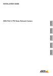
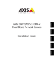
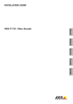
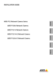
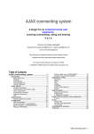
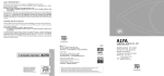
INSTALLATION GUIDE AXIS M32 Network Camera Series ENGLISH AXIS M3203 Network Camera AXIS M3203-V Network Camera AXIS M3204-V Network Camera FRANÇAIS AXIS M3204 Network Camera DEUTSCH ITALIANO ESPAÑOL About this Document This document includes instructions for installing AXIS AXIS M3203/-V/3204/-V Network Camera on your network. Previous experience of networking will be beneficial when installing the product. Legal Considerations Video and audio surveillance can be prohibited by laws that vary from country to country. Check the laws in your local region before using this product for surveillance purposes. This product includes one (1) H.264 decoder license. To purchase further licenses, contact your reseller. Trademark Acknowledgments AXIS COMMUNICATIONS, AXIS, ETRAX, ARTPEC and VAPIX are registered trademarks or trademark applications of Axis AB in various jurisdictions. All other company names and products are trademarks or registered trademarks of their respective companies. Apple, Boa, Apache, Bonjour, Ethernet, Internet Explorer, Linux, Microsoft, Mozilla, Real, SMPTE, QuickTime, UNIX, Windows, Windows Vista and WWW are registered trademarks of the respective holders. Java and all Java-based trademarks and logos are trademarks or registered trademarks of Oracle and/or its affiliates. UPnPTM is a certification mark of the UPnPTM Implementers Corporation. SD, SDHC and SDXC are trademarks or registered trademarks of SD-3C, LLC in the United States, other countries or both. Also, miniSD, microSD, miniSDHC, microSDHC, microSDXC are all trademarks or registered trademarks of SD-3C, LLC in the United States, other countries or both. WPA, WPA2 and Wi-Fi Protected Setup are marks of the Wi-Fi Alliance. Microsoft, Windows, Windows Vista, WWW, Internet Explorer, DirectX, Intel, Intel Core, Pentium and Xeon are registered trademarks of the respective holders. Acrobat, Adobe, Apache, Debian, Ethernet, Internet Explorer, Iomega, LaCie, Linux, Machintosh, Microsoft, Mozilla, MySQL, Red Hat, UNIX, Windows, WWW, Wi-Fi are registered trademarks of the respective holders. Java and all Java-based trademarks and logos are trademarks or registered trademarks of Oracle and/or its affiliates. UPnPTM is a certification mark of the UPnPTM Implementers Corporation. WPA is a mark of the Wi-Fi Alliance. Electromagnetic Compatibility (EMC) This equipment has been designed and tested to fulfill applicable standards for: • Radio frequency emission when installed according to the instructions and used in its intended environment. • Immunity to electrical and electromagnetic phenomena when installed according to the instructions and used in its intended environment. USA - Using a shielded network cable (STP): This equipment has also been tested using a shielded network cable (STP) and found to comply with the limits for a Class B digital device, pursuant to part 15 of the FCC Rules. These limits are designed to provide reasonable protection against harmful interference in a residential installation. This equipment generates, uses and can radiate radio frequency energy and, if not installed and used in accordance with the instructions, may cause harmful interference to radio communications. However, there is no guarantee that interference will not occur in a particular installation. If this equipment does cause harmful interference to radio or television reception, which can be determined by turning the equipment off and on, the user is encouraged to try to correct the interference by one or more of the following measures: • Reorient or relocate the receiving antenna. • Increase the separation between the equipment and receiver. • Connect the equipment into an outlet on a circuit different from that to which the receiver is connected. • Consult the dealer or an experienced radio/TV technician for help. Canada - This Class B digital apparatus complies with Canadian ICES-003. Europe This digital equipment fulfills the requirements for RF emission according to the Class B limit of EN 55022. This product fulfills the requirements for immunity according to EN 55024 office and commercial environments. Australia - This digital equipment fulfills the requirements for RF emission according to the Class B limit of AS/NZS CISPR 22. Korea - ࢇ̛̛Еɼࢽࡈ%̗ࢷળࢶଢ̛̛Ի۰ ࣯Իɼࢽ߾۰ࡈیଜЕʨࡶּࢶࡳԻଜֲֻҘ एࠇ߾۰ࡈیଟܹݡТЬ Japan - この装置は、クラスB 情報技術装置です。この 装置は、家庭環境で使用することを目 的としていますが 、この装置がラジオやテレビジョン受信機に近接して使 用されると、 受信障害を引き起こすことがあります。 取扱説明書に従って正しい取り扱いをして下さい。 Safety This product complies to EN/IEC 60950-1, Safety of Information Technology Equipment. Equipment Modifications This equipment must be installed and used in strict accordance with the instructions given in the user documentation. This equipment contains no user-serviceable components. Unauthorized equipment changes or modifications will invalidate all applicable regulatory certifications and approvals. Liability Every care has been taken in the preparation of this document. Please inform your local Axis office of any inaccuracies or omissions. Axis Communications AB cannot be held responsible for any technical or typographical errors and reserves the right to make changes to the product and documentation without prior notice. Axis Communications AB makes no warranty of any kind with regard to the material contained within this document, including, but not limited to, the implied warranties of merchantability and fitness for a particular purpose. Axis Communications AB shall not be liable nor responsible for incidental or consequential damages in connection with the furnishing, performance or use of this material. This product is only to be used for its intended purpose. Intellectual Property Rights Axis AB has intellectual property rights relating to technology embodied in the product described in this document. In particular, and without limitation, these intellectual property rights may include one or more of the patents listed at http:// www.axis.com/patent.htm and one or more additional patents or pending patent applications in the US and other countries. This product contains licensed third-party software. See the menu item “About” in the product’s user interface for more information. This product contains source code copyright Apple Computer, Inc., under the terms of Apple Public Source License 2.0 (see http:// www.opensource.apple.com/apsl). The source code is available from http:// developer.apple. com/darwin/projects/ bonjour/ Disposal and Recycling Europe - This symbol means that the product shall not be disposed of together with household or commercial waste. Directive 2012/19/ EU on waste electrical and electronic equipment (WEEE) is applicable in the European Union member states. To prevent potential harm to human health and the environment, the product must be disposed of in an approved and environmentally safe recycling process. For information about your nearest designated collection point, contact your local authority responsible for waste disposal. Businesses should contact the product supplier for information about how to dispose of this product correctly. This product complies with the requirements of Directive 2011/65/EU on the restriction of the use of certain hazardous substances in electrical and electronic equipment (RoHS). China - This product complies with the requirements of the legislative act Administration on the Control of Pollution Caused by Electronic Information Products (ACPEIP). Support Should you require any technical assistance, please contact your Axis reseller. If your questions cannot be answered immediately, your reseller will forward your queries through the appropriate channels to ensure a rapid response. If you are connected to the Internet, you can: • download user documentation and firmware updates • find answers to resolved problems in the FAQ database. Search by product, category, or phrases • report problems to Axis support by logging in to your private support area • chat with Axis support staff (selected countries only) • visit Axis Support at www.axis.com/techsup/ Should you require any technical assistance, please contact appropriate channels according to your AVHS license agreement to ensure a rapid response. Learn More! Visit Axis learning center www.axis.com/ academy/ for useful trainings, webinars, tutorials and guides. Safeguards Please read through this Installation Guide carefully before installing the Axis product. Keep the Installation Guide for further reference. • • • • • • • • This Axis product shall be used in compliance with local laws and regulations. To use this Axis product outdoors, it shall be installed in an approved outdoor housing. ENGLISH • Store the Axis product in a dry and ventilated environment. Avoid exposing the Axis product to vibration, shocks or heavy pressure. Do not install the product on unstable brackets, unstable or vibrating surfaces or walls, since this could cause damage to the product. Only use applicable tools when installing the Axis product; excessive force could cause damage to the product. Do not use chemicals, caustic agents, or aerosol cleaners. Use a damp cloth for cleaning. Use only accessories that comply with technical specification of the product. These can be provided by Axis or a third party. Use only spare parts provided by or recommended by Axis. Do not attempt to repair the product by yourself, contact Axis or your Axis reseller for service matters. AXIS M32 Series Page 7 AXIS M32 Series Installation Guide This installation guide provides instructions for installing the AXIS M32 Series on your network. For all other aspects of using the product, please see the User Manual, available from www.axis.com/techsup 1. 2. 3. 4. 5. 6. Package contents. See below. Hardware overview. See page 8. Install the hardware. See page 9. Access the video stream. See page 10 Adjust the focus. See page 11. Complete the installation. See page 11. Important! This product must be used in compliance with local laws and regulations. Package contents Item Models/variants/notes Network camera models AXIS M3203 - Tamper-resistant Network Camera AXIS M3203-V - Vandal-resistant Network Camera AXIS M3204 - Tamper-resistant Network Camera AXIS M3204-V - Vandal-resistant Network Camera Mounting kit Screwdriver for tamper-proof screws 2 tamper-proof screws (M4x16 Resitorx) Drill template CD Installation and Management Software CD Printed Materials AXIS M32 Series Installation Guide (this document), AVHS Authentication key ENGLISH Installation steps Page 8 AXIS M32 Series Hardware overview Status indicator LED Cover plates Control button Network connector Network indicator LED Power indicator LED Product ID & Serial number (S/N). The serial number may be required during the installation. Dimensions and weight HxWxD = 94 x 144 x 132mm (3.7" x 5.7" x 5.2") AXIS M3203, AXIS M3204: 425 g (0.94 lb) AXIS M3203-V, AXIS M3204-V: 580 g (1.28 lb) 16mm cable conduit (not supplied) fitted to AXIS M32 series AXIS M32 Series Page 9 Install the hardware IMPORTANT! - The casing of AXIS M3203-V and AXIS M3204-V is not approved for outdoor use - the product may only be installed in indoor environments. The AXIS M32 Series network cameras can be mounted with the cables routed through the wall/ceiling, or from above or below. There are cover plates for the openings on both sides of the dome cover. The AXIS M32 Series can also be fitted with a metal conduit for protecting the cabling when connected via the side openings. See the illustrations on page 8. 1. 2. 3. 4. Using the drill template, drill two holes in the ceiling/wall. Ensure the camera is positioned so that the tamper-proof screws can be tightened using the supplied screwdriver. Route the required cables. Fasten the camera unit to the ceiling or wall, using screws and plugs appropriate for the ceiling/wall material. Proceed to Access the video stream, on page 10. ENGLISH Mount the camera Page 10 AXIS M32 Series Mounting on a drop ceiling To mount the AXIS M32 Series on a drop ceiling, check that the ceiling is sturdy enough to hold the weight of the camera. The camera can also be secured using a plate or board that better carries the weight of the camera, and which is more suitable for securing the screws. Plate or board Ceiling AXIS M32 Network Cmera Screws The AXIS M32 Series can also be mounted using the AXIS M32 Series Drop Ceiling Mount, which allows the camera to be mounted more discreetly. Please see www.axis.com for all available mounting accessories. Access the video stream Use the tools provided on the Installation and Management Software CD to assign an IP address, set the password and access the video stream. This information is also available from the support pages on www.axis.com/techsup AXIS M32 Series Page 11 Adjust the image and focus Open the Live View page in the web interface and make the following adjustments to the camera: 1. focus once the dome has been placed. Focus on an object slightly closer than the intended area to compensate for this. The image can also be fine-tuned for low light conditions. Go to Setup > Video > Camera Settings in the camera’s web interface and see the online help for more information. Complete the installation 1. 2. Rotate the black protective shield inside the dome casing to match the camera’s position. Clean the dome with a dry soft cloth to remove dust and finger prints and use a blower to remove dust from the lens. ENGLISH Loosen the locking Locking screw Image balance ring screw and tilt adjustment screws. 2. Turn the lens to the desired position. 3. Once satisfied, gently Tilt adjustment tighten the locking screw screw and tilt (on each side) adjustment screws to Zoom puller secure the camera’s Focus puller position. 4. Turn the image balance ring to set the horizontal position. 5. To set the focus and zoom, loosen the zoom and focus pullers anticlockwise and rotate the rings. 6. Lock the focus and zoom pullers in position by rotating the screws clockwise. Note: Due to the dome’s refraction, the image may appear slightly out of Page 12 AXIS M32 Series 3. Mount the dome casing using the supplied tamper-proof screws and screw driver. 4. Now that the dome is in place, double-check that the camera is properly focused. The installation is now complete. LED indicators LED Color Indication Network Green Steady for connection to a 100 Mbit/s network. Flashes for network activity. Amber Steady for connection to 10 Mbit/s network. Flashes for network activity. Unlit No network connection. Green Steady green for normal operation. Note: The Status LED can be configured to be unlit during normal operation, or to flash only when the camera is accessed. To configure, go to Setup > System Options > LED. See the online help files for more information. Amber Steady during startup, during reset to factory default or when restoring settings. Red Slow flash for failed upgrade. Green Normal operation. Amber Flashes green/amber during firmware upgrade. Status Power AXIS M32 Series Page 13 Resetting to the Factory Default Settings This will reset all parameters, including the IP address, to the Factory Default settings: 1. 2. 3. Further information The User Manual is available from the Axis Web site at www.axis.com. Visit www.axis.com/techsup to check if there is updated firmware available for AXIS M32 Series To see the currently installed firmware version, see Setup > About in the camera’s web pages. Warranty For information about Axis' product warranty and thereto related information, please see www.axis.com/warranty ENGLISH Disconnect power from the camera. Press and hold the Control button and reconnect power. Keep the Control button pressed until the Power indicator flashes amber (this may take up to 15 seconds). 4. Release the Control button. When the Power indicator displays green (which can take up to 1 minute) the process is complete and the camera has been reset. 5. Re-assign the IP address, using one of the methods described in this document. It is also possible to reset parameters to the original factory default settings via the web interface. For more information, please see the online help or the user’s manual. Mesures de sécurité Lisez attentivement le présent Guide d'installation avant d'installer le produit Axis. Conservez le Guide d'installation pour une utilisation ultérieure. • • • • • • FRANÇAIS • Conservez le produit Axis dans un environnement sec et aéré. Évitez d'exposer le produit Axis aux vibrations, aux chocs ou à une forte pression. N'installez pas le produit sur un support instable, ou des surfaces ou des murs instables ou vibrants, car cela pourrait l'endommager. N'utilisez que les outils applicables pour installer le produit Axis ; une force excessive pourrait endommager le produit. Pour le nettoyage, n’utilisez ni produits chimiques, ni substances caustiques ou aérosols. Utilisez un chiffon humide pour le nettoyage. N’utilisez que des accessoires conformes aux caractéristiques techniques du produit. Ceux-ci peuvent être fournis par Axis ou par un fournisseur tiers. Utilisez uniquement des pièces de rechange fournies ou recommandées par Axis. Ne tentez pas de réparer le produit vous-même, contactez Axis ou votre revendeur Axis pour toute réparation. • • Ce produit Axis doit être utilisé conformément aux lois et réglementations locales en vigueur. Pour pouvoir être utilisé à l'extérieur, ce produit Axis doit être placé dans un boîtier d'extérieur homologué. AXIS M32 Series Page 17 AXIS M32 Series Guide d’installation Ce guide d’installation explique comment installer la caméra réseau AXIS Série M32 sur votre réseau. Pour toute autre question concernant l’utilisation du produit, reportez-vous au Manuel de l’utilisateur que vous trouverez sur le CD joint ou sur le site www.axis.com/techsup Procédure d’installation Vérifiez le contenu de l’emballage par rapport à la liste ci-dessous. Description du matériel. Cf. page 18. Installation du matériel. Cf. page 19. Accéder au flux vidéo Cf.page 20 . Réglage de la mise au point. Cf. page 21. Fin de l’installation. Cf. page 22 Contenu de l’emballage Élément Modèles/variantes/remarques Caméra réseau à dôme fixe AXIS M3203 - Caméra réseau inviolable AXIS M3203-V - Caméra réseau résistant au vandalisme AXIS M3204 - Caméra réseau inviolable AXIS M3204-V - Caméra réseau résistant au vandalisme Kit de montage Tournevis pour vis inviolables, 2 vis inviolables (M4x16 Resitorx), Gabarit de perçage CD CD d’installation contenant les logiciels de gestion vidéo Documentation imprimée AXIS M32 Series Installation Guide (this document), AVHS Authentication key FRANÇAIS 1. 2. 3. 4. 5. 6. Page 18 AXIS M32 Series Description du matériel Voyant d’état Plaques d’obturation Bouton de commande . ID du produit et numéro de série (S/N) Le numéro de série peut être demandé pendant l’installation. Connecteur réseau Voyant d’alimentation Voyant réseau Dimensions: H x L x P = 94 x 144 x 132 mm (3.7" x 5.7" x 5.2") AXIS M3203, AXIS M3204: 425 g (0.94 lb) AXIS M3203-V, AXIS M3204-V: 580 g (1.28 lb) Conduit de câbles 16 mm (non fourni) installé sur une série AXIS M32 AXIS M32 Series Page 19 Installation du matériel IMPORTANT ! - Il n’est pas recommandé d’utiliser le boîtier de l’AXIS M3203-V et de l’AXIS M3204-V à l’extérieur. Le produit doit être installé en intérieur uniquement. Montage de la caméra 1. 2. 3. 4. En vous servant du gabarit de perçage, percez deux trous dans le plafond/mur. Veillez à ce que la caméra soit positionnée de telle manière que les vis inviolables puissent être serrées à l’aide du tournevis fourni. Acheminez les câbles nécessaires. Pour plus d’informations, consultez la section . Fixez la caméra au plafond ou au mur à l’aide des vis et des chevilles appropriées. Passez à la section Accéder au flux vidéo, on page 20. FRANÇAIS Les caméras réseau AXIS M32 Series peuvent être montées avec les câbles d’alimentation et réseau acheminés dans le mur/plafond, ou depuis le haut ou le bas. Vous disposez de plaques d’obturation pour les ouvertures des deux côtés du capot du dôme. La caméra AXIS M32 Series peut être également dotée d’un conduit métallique pour protéger les câbles lors d’une connexion par les ouvertures latérales. Consultez les schémas de la page 18. Page 20 AXIS M32 Series Montage sur faux-plafond Pour monter la caméra AXIS M32 Series sur un faux-plafond, vérifiez que le plafond est assez solide pour supporter le poids de la caméra. La caméra peut être également fixée à l’aide d’une plaque ou d’une planche qui peut supporter le poids de la caméra et qui peut être plus adaptée pour la fixation des vis. Plaque ou planche Plafond AXIS M32 Series Vis La caméra AXIS M32 Series peut être également montée à l’aide du kit de montage pour faux-plafond AXIS M32 Series, qui permet un montage plus discret. Visitez www.axis.com pour découvrir les accessoires de montage disponibles. Accéder au flux vidéo Utilisez les outils fournis dans le CD d’installation contenant les logiciels de gestion vidéo pour attribuer une adresse IP, définir le mot de passe et accéder au flux vidéo. Ces informations sont également disponibles sur les pages de support en ligne à l’adresse www.axis.com/techsup AXIS M32 Series Page 21 Réglage de l’image et de la mise au point Ouvrez la page Live View (Vidéo en direct) dans l’interface Internet et effectuez les réglages suivants sur la caméra : 1. floue une fois le dôme installé. Effectuez la mise au point sur un objet légèrement plus proche que la zone cible pour compenser ce défaut. L’image peut également être ajustée en cas de faible éclairage. Accédez à Setup > Video > Camera Settings (Configuration > Vidéo > Réglages caméra) dans l’interface Web de la caméra et consultez l’aide en ligne pour plus d’informations. FRANÇAIS Anneau d’équilibrage d’image Desserrez la vis de Vis de verrouillage verrouillage et les vis de réglage de l’inclinaison. 2. Tournez l’objectif dans la position Vis de réglage souhaitée. de l’inclinaison 3. Une fois que vous (de chaque côté) avez terminé, serrez Point Zoom délicatement la vis de Dispositif de m verrouillage et les vis de réglage de l’inclinaison pour bien fixer la caméra. 4. Tournez l’anneau d’équilibrage d’image pour définir la position horizontale. 5. Pour régler le zoom et la mise au point, desserrez les commandes correspondantes en tournant dans le sens inverse des aiguilles d’une montre, puis faites tourner les anneaux. 6. Verrouillez les commandes de zoom et de mise au point en serrant les vis dans le sens des aiguilles d’une montre. Note: Du fait de la réfraction du dôme, L’image peut apparaître légèrement Page 22 AXIS M32 Series Fin de l’installation 1. Tournez l’écran protecteur noir à l’intérieur du boîtier du dôme, conformément à la position de la caméra. 2. Nettoyez le dôme avec un chiffon doux et sec pour enlever la poussière et les traces de doigt. Dépoussiérez l’objectif avec un ventilateur. 3. Montez le boîtier du dôme à l’aide des vis inviolables et du tournevis fournis. 4. Une fois le dôme en place, vérifiez une nouvelle fois que la mise au point est correctement réglée. L’installation est terminée. AXIS M32 Series Page 23 Voyants lumineux Couleur Indication Réseau Vert Continu en cas de connexion à un réseau de 100 Mbits/s. Clignote en cas d’activité réseau. Orange Continu en cas de connexion à un réseau de 10 Mbits/s. Clignote en cas d’activité réseau. Éteint Pas de connexion au réseau. Vert Vert continu en cas de fonctionnement normal. Remarque : le voyant d’état peut être configuré pour être éteint pendant le fonctionnement normal ou pour clignoter uniquement en cas d’accès à la caméra. Pour ce faire, cliquez sur Setup > System Options > LED (Configuration > Options système > DEL). Reportez-vous à l’aide en ligne pour plus d’informations. Orange Continu pendant le démarrage, la réinitialisation des paramètres d’usine par défaut ou la restauration des paramètres. Rouge Clignote lentement en cas d’échec de la mise à niveau. Vert Fonctionnement normal. Orange Clignote en vert/orange pendant la mise à niveau des micrologiciels. État Alimentation FRANÇAIS Voyant Page 24 AXIS M32 Series Rétablissement des paramètres d’usine par défaut Procédez comme suit pour rétablir tous les paramètres par défaut définis en usine, y compris l’adresse IP : 1. 2. Débranchez l’alimentation de la caméra. Maintenez le bouton de commande enfoncé et rebranchez l’alimentation. 3. Appuyez sur le bouton jusqu'à ce que le voyant d’alimentation passe à l’orange et clignote (cela peut prendre jusqu'à 15 secondes). 4. Relâchez le bouton de commande. Une lumière verte émise par le voyant d’alimentation (peut prendre 1 minute) indique que l’opération est terminée et que la caméra a été réinitialisée. 5. Attribuez à nouveau l’adresse IP à l’aide de l’une des méthodes décrites dans ce document. Il est également possible de rétablir les paramètres d’usine par défaut d’origine à partir de l’interface Web. Pour obtenir plus d’informations, reportez-vous à l’aide en ligne ou au manuel d’utilisation. Plus d’informations Le manuel de l’utilisateur est disponible sur le site Web d’Axis (www.axis.com). Conseil: Visitez le site www.axis.com/techsup pour vérifier si des micrologiciels mis à jour sont disponibles pour votre caméra réseau Série AXIS M32. Pour connaître la version du micrologiciel actuellement installée, reportez-vous à la page Setup > About (Configuration > À propos de). Garantie Pour plus d'informations sur la garantie des produits Axis et des informations générales relatives à celle-ci merci de consulter le site www.axis.com/warranty Sicherheitsvorkehrungen Bitte lesen Sie diese Installationsanleitung sorgfältig durch, bevor Sie mit der Installation des Axis Produkts beginnen. Halten Sie die Installationsanleitung bereit, falls Sie darauf zurückgreifen müssen. • • • • • • DEUTSCH • Lagern Sie das Axis-Produkt in einer trockenen und belüfteten Umgebung. Setzen Sie das Axis Produkt keinen Vibrationen, Erschütterungen oder starkem Druck aus. Installieren Sie das Produkt nicht an instabilen Halterungen oder instabilen oder vibrierenden Oberflächen oder Mauern, da dadurch das Produkt beschädigt werden könnte. Verwenden Sie bei der Installation des Axis Produkts nur geeignetes Werkzeug; zu hoher Kraftaufwand kann das Produkt beschädigen. Verwenden Sie keine chemischen, ätzenden oder aerosolhaltigen Reinigungsmittel. Verwenden Sie zur Reinigung ein feuchtes Tuch. Verwenden Sie nur Zubehör, das den technischen Spezifikationen des Produkts entspricht. Dieses ist von Axis oder Drittanbietern erhältlich. Verwenden Sie nur Ersatzteile, die von Axis empfohlen bzw. bereitgestellt wurden. Versuchen Sie nicht, das Produkt selbst zu reparieren. Wenden Sie sich bei Service-Angelegenheiten an Axis oder an Ihren Axis-Händler. • • Verwenden Sie dieses Axis-Produkt unter Beachtung der vor Ort geltenden rechtlichen Bestimmungen. Um dieses Axis-Produkt im Freien verwenden zu können, muss es in einem zugelassenen Außengehäuse installiert werden. AXIS M32 Series Page 27 AXIS M32 Series Installationsanleitung In dieser Anleitung wird die Installation der Fixed Dome Network Cameras der AXIS M32 Series in einem Netzwerk beschrieben. Alle weiteren Hinweise zur Verwendung des Produkts finden Sie im Benutzerhandbuch, das auf der mitgelieferten CD sowie auf unserer Website unter „www.axis.com/techsup“ zur Verfügung steht. Installationsschritte 1. 2. 3. 4. 5. 6. Prüfen Sie, ob alle in der nachfolgenden Liste aufgeführten Komponenten vorhanden sind. Sehen Sie sich die Hardwareübersicht an. Siehe page 29. Installieren Sie die Hardware. Siehe page 30. Zugriff auf den Video Stream. Siehe page 31. Stellen Sie die Bildschärfe ein. Siehe page 32. Schließen Sie die Installation ab. Siehe page 33. Lieferumfang Modelle/Varianten/Anmerkungen Netzwerk Kamera AXIS M3203 - Manipulationsgeschützte Network Camera AXIS M3203-V - Vandalismusgeschützte Network Camera AXIS M3204 - Manipulationsgeschützte Network Camera AXIS M3204-V - Vandalismusgeschützte Network Camera Montagesatz Schraubendreher für manipulationssichere Schrauben zwei manipulationssichere Schrauben (M4x16 Resitorx) Bohrschablone CD-ROM Installations- und Management-Software CD DEUTSCH Komponente Page 28 AXIS M32 Series Komponente Modelle/Varianten/Anmerkungen Gedruckte Dokumente Installationsanleitung für die AXIS M32 Series (dieses Dokument) AVHS-Authentifizierungsschlüssel AXIS M32 Series Page 29 Hardwareübersicht Statusanzeige (LED) Abdeckplatten Steuertaste Seriennummer (S/N). Die Seriennummer wird für die Installation benötigt. Netzwerkanzeige (LED) Betriebsanzeige Abmessungen H × B × T = 94 x 144 x 132 mm (3.7" x 5.7" x 5.2") AXIS M3203, AXIS M3204: 425 g (0.94 lb) AXIS M3203-V, AXIS M3204-V: 580 g (1.28 lb) 16-mm-Kabelführung (nicht mitgeliefert) angebracht an AXIS M32 Serie DEUTSCH Netzwerkanschluss Page 30 AXIS M32 Series Installation der Hardware WICHTIG! - Das Gehäuse der AXIS M3203-V und AXIS M3204-V ist nicht für den Einsatz im Außenbereich geeignet. Diese Kameramodelle dürfen nur in Innenräumen installiert werden. Montieren der Kamera Für die Montage der Netzwerk-Kameras der AXIS M32 Series können die Kabel durch die Wand/Decke oder von oben bzw. unten verlegt werden. Für die Öffnungen auf beiden Seiten der Kuppelhaube sind Abdeckplatten vorhanden. Die AXIS M32 Series kann auch mit einer Kabelführung aus Metall ausgestattet werden, um die Verkabelung zu schützen, wenn der Anschluss über die seitlichen Öffnungen erfolgt. Siehe Abbildungen auf page 29. 1. 2. 3. 4. Bohren Sie mithilfe der Bohrschablone zwei Löcher in die Decke bzw. Wand. Die Kamera muss so platziert werden, dass die manipulationssicheren Schrauben mit dem mitgelieferten Schraubendreher festgezogen werden können. Ziehen Sie die erforderlichen Kabel. Weitere Informationen finden Sie unter . Schrauben Sie die Kameraeinheit an der Decke bzw. Wand fest. Verwenden Sie dazu die Schrauben und Dübel, die für das Material der Decke bzw. der Wand geeignet sind. Fahren Sie mit fort Zugriff auf den Video Stream, on page 31. AXIS M32 Series Page 31 Hängedeckenmontage Wenn die Kamera der AXIS M32 Series an einer Hängedecke befestigt werden soll, müssen Sie überprüfen, ob das Deckenmaterial stabil genug ist, um das Gewicht der Kamera zu tragen. Die Kamera kann auch unter Verwendung einer Platte oder einem Brett befestigt werden. Das bietet eine bessere Tragfähigkeit und erleichtert das Befestigen der Schrauben. Platte oder Brett Decke AXIS M32 Serie Schrauben Zugriff auf den Video Stream Verwenden Sie die Werkzeuge auf der Installations- und ManagementSoftware CD, um IP-Adressen zuzuweisen, das Passwort festzulegen und auf den Videostream zuzugreifen. Sie finden diese Informationen auch auf den Support-Seiten unter www.axis.com/techsup DEUTSCH Die AXIS M32 Series kann auch unter Verwendung des AXIS M32 SeriesMontagesatzes für Hängedecken befestigt werden, um sie unauffälliger anzubringen. Mehr Information zum gesamten Befestigungszubehör finden Sie unter www.axis.com. Page 32 AXIS M32 Series Bildschärfe einstellen Öffnen Sie die Seite Live View (Live-Ansicht) und nehmen Sie folgende Einstellung an der Kamera vor: 1. Lösen Sie die FestLocking screw Image balance ring stellschraube und die Einstellschrauben- für die Neigung. 2. Drehen Sie das Objektiv in die Tilt adjustment gewünschte Position. screw 3. Wenn die richtige (on each side) Ausrichtung erreicht Zoom puller ist, schrauben Sie die Focus puller Feststellschraube und die Einstellschrauben für die Neigung vorsichtig wieder fest, um die Kameraposition zu sichern. 4. Stellen Sie mit dem Ring zum Bildausgleich die horizontale Ausrichtung ein. 5. Lösen Sie für die Einstellung der Bildschärfe und des Zooms die Regler für Zoom und Fokus entgegen dem Uhrzeigersinn und drehen Sie die Ringe. 6. Arretieren Sie Zoomregler und Schärferegler in der gewählten Position. Ziehen Sie dazu die Schrauben im Uhrzeigersinn fest. Note: Aufgrund der Lichtbrechungen auf der Glasoberfläche kann das Bild leicht unscharf erscheinen, nachdem die Kuppel installiert wurde. Um diesen Effekt auszugleichen, stellen Sie die Kamera auf ein Objekt scharf, dass etwas näher als der zu erfassende Bereich liegt. Sie können auch eine Feinabstimmung des Bildes für schlechte Lichtverhältnisse vornehmen. Weitere Informationen hierzu finden Sie in der Online-Hilfe unter Setup > Video > Camera Settings (Setup > Video > Kameraeinstellungen) in der Weboberfläche der Kamera. AXIS M32 Series Page 33 Installation abschließen 1. 2. 3. 4. Bringen Sie das schwarze Schutzschild in der Kuppelhaube durch Drehen in Übereinstimmung mit der Kameraposition. Entfernen Sie Fingerabdrücke und Staub mit einem trockenen, weichen Tuch von der Glasoberfläche. Blasen Sie Staub ggf. mit Druckluft von der Linse. Befestigen Sie die Kuppelhaube mit Hilfe der im Lieferumfang enthaltenen manipulationssicheren Schrauben und des Schraubendrehers. Wenn die Kamera angebracht ist, vergewissern Sie sich sorgfältig, dass die Schärfe richtig eingestellt ist. Die Installation ist damit abgeschlossen. DEUTSCH Page 34 AXIS M32 Series LED-Anzeigen LED Farbe Bedeutung Netzwerk Grün Leuchtet dauerhaft bei Verbindung mit einem 100-MBit/s-Netzwerk. Blinkt bei Netzwerkaktivität. Gelb Leuchtet dauerhaft bei Verbindung mit einem 10-MBit/s-Netzwerk. Blinkt bei Netzwerkaktivität. Leuchtet nicht Keine Netzwerkverbindung vorhanden. Grün Leuchtet bei Normalbetrieb konstant grün. Hinweis: Die Status-LED kann so konfiguriert werden, dass sie bei normalem Betrieb nicht leuchtet oder nur dann blinkt, wenn auf die Kamera zugegriffen wird. Diese Konfiguration können Sie unter Setup > System Options > LED (Setup > Systemoptionen > LED) vornehmen. Weitere Informationen hierzu finden Sie in der Online-Hilfe. Gelb Leuchtet konstant beim Einschalten und beim Wiederherstellen der Werkseinstellungen bzw. von vorherigen Einstellungen. Rot Blinkt langsam bei Aktualisierungsfehler. Grün Normaler Betrieb. Gelb Blinkt grün/gelb während FirmwareAktualisierung. Status Stromversorgung AXIS M32 Series Page 35 Wiederherstellen der werkseitigen Standardeinstellungen Gehen Sie wie folgt vor, um sämtliche Parameter einschließlich der IPAdresse auf die werkseitigen Standardeinstellungen zurückzusetzen: 1. 2. Trennen Sie die Kamera von der Stromversorgung. Halten Sie die Steuertaste gedrückt und schließen Sie den Netzstecker wieder an. 3. Halten Sie die Steuertaste so lange gedrückt, bis die Betriebsanzeige gelb blinkt (dies kann bis zu 15 Sekunden dauern). 4. Lassen Sie die Steuertaste los. Sobald die Betriebsanzeige grün leuchtet (dies kann bis zu 1 Minute dauern), ist die Kamera auf die werkseitigen Standardeinstellungen zurückgesetzt. 5. Legen Sie die IP-Adresse erneut fest. Wenden Sie dabei eines der in diesem Handbuch beschriebenen Verfahren an. Die Parameter können auch über die Weboberfläche auf die werkseitigen Einstellungen zurückgesetzt werden. Weitere Informationen dazu finden Sie in der Online-Hilfe und im Benutzerhandbuch. Das Benutzerhandbuch ist auf der Axis Website unter „http:// www.axis.com“ Tipp! Unter „www.axis.com/techsup“ finden Sie Firmware-Aktualisierungen für Ihre Netzwerk-Kamera der AXIS M32 Series. Informationen zur aktuellen Firmware-Version finden Sie unter Setup > Info. Garantie Die Garantiebedingungen für Axis Produkte sowie weitere Informationen zum Thema Garantie finden Sie unter www.axis.com/warranty DEUTSCH Weitere Informationen Sicurezza Leggere attentamente questa Guida all'installazione prima di installare un prodotto Axis. Conservare la Guida all'installazione per ulteriori riferimenti. • • • • • • ITALIANO • Conservare il prodotto Axis in un ambiente asciutto e ben ventilato. Evitare di esporre il prodotto Axis alle vibrazioni, agli urti o a forte pressione. Non installare il prodotto su staffe instabili, superfici o pareti instabili o vibranti, poiché ciò potrebbe danneggiare il prodotto. Utilizzare solo strumenti idonei quando si installa il prodotto Axis. Una forza eccessiva potrebbe danneggiare il prodotto. Non utilizzare sostanze chimiche, agenti caustici o detergenti spray. Utilizzare un panno umido per la pulizia. Utilizzare solo accessori conformi con le specifiche tecniche del prodotto. Queste possono essere fornite da Axis o da terze parti. Utilizzare solo parti di ricambio fornite o raccomandate da Axis. Non tentare di riparare il prodotto da soli, contattare Axis o il rivenditore di zona Axis per assistenza. • • Questo prodotto Axis deve essere utilizzato in conformità alle leggi e alle disposizioni locali. Per utilizzare questo prodotto Axis all'esterno, è necessario installarlo in un alloggiamento per esterni approvato. AXIS M32 Series Page 39 AXIS M32 Series Guida all’installazione Questo documento fornisce le istruzioni necessarie per installare le Fixed Dome Network Cameras AXIS M32 Series nella rete in uso. Per ulteriori informazioni sull’utilizzo del prodotto, consultare la Guida per l’utente disponibile sul CD incluso nella confezione oppure visitare il sito web all’indirizzo www.axis.com/techsup. Procedura di installazione 1. Controllare il contenuto della confezione utilizzando l’elenco fornito di seguito. Panoramica dell’hardware. Vedere a page 41. Installazione dell’hardware. Vedere a page 42. Accesso al flusso video. Vedere apage 43 . Completamento dell’installazione. Vedere a page 45. 2. 3. 4. 5. Contenuto della confezione Modelli/varianti/note Telecamera di rete a cupola fissa AXIS M3203 - Telecamera di rete resistente alle manomissioni AXIS M3203-V - Telecamera di rete resistente agli atti vandalici AXIS M3204 - Telecamera di rete resistente alle manomissioni AXIS M3204-V - Telecamera di rete resistente agli atti vandalici Kit di montaggio Cacciavite per viti antimanomissione, 2 viti antimanomissione (M4x16 Resitorx), Sagoma per la foratura CD CD d’Installazione e Gestione ITALIANO Articolo Page 40 AXIS M32 Series Articolo Modelli/varianti/note Documentazione cartacea Guida all’installazione della telecamera AXIS M32 Series (questo documento), chiave di autenticazione AVHS AXIS M32 Series Page 41 Panoramica dell’hardware LED di stato Coperture Pulsante di comando ID prodotto e numero di serie (S/N). Il numero di serie è talvolta richiesto durante l’installazione. Indicatore di alimentazione Connettore di rete Indicatore di rete (LED) ITALIANO Dimensioni A x L x P = 94 x 144 x 132 mm (3.7" x 5.7" x 5.2") AXIS M3203, AXIS M3204: 425 g (0,94 lb) AXIS M3203-V, AXIS M3204-V: 580 g (1.28 lb) Cavo da 16 mm (non fornita) adattata alla serie AXIS M32 Page 42 AXIS M32 Series Installazione dell’hardware IMPORTANTE! - L’alloggiamento dei modelli AXIS M3203-V e AXIS M3204-V non è approvato per l'utilizzo in ambienti esterni. I prodotti possono essere installati soltanto in ambienti interni Montaggio della telecamera La telecamera AXIS M32 Series può essere montata con i cavi di rete e di alimentazione incassati nella parete o nel soffitto oppure inseriti dall’alto o dal basso. Sono previste aperture su entrambi i lati della copertura della cupola. La AXIS M32 Series può essere munita di un conduttore in metallo per proteggere i cavi nel caso in cui siano collegati tramite aperture laterali. Vedere le illustrazioni a page 41. 1. 2. 3. 4. Eseguire due fori nel soffitto o nella parete utilizzando la sagoma fornita nella confezione. Verificare che la telecamera sia posizionata correttamente e che sia possibile stringere le viti antimanomissione con l’apposito cacciavite incluso nella confezione. Collegare i cavi richiesti. Vedere per informazioni dettagliate. Bloccare la telecamera alla parete o al soffitto mediante viti e tasselli appropriati. Passare a Accesso al flusso video, on page 43. AXIS M32 Series Page 43 Montaggio su un controsoffitto Prima di montare la telecamera AXIS M32 Series su un controsoffitto, verificare che lo stesso sia abbastanza solido per sostenere il peso della telecamera. La telecamera può essere fissata utilizzando una tavola o una lastra in modo da sostenerne il peso, una tavola od una lastra sono inoltre piu' adatte al serraggio delle viti. Tavola o lastra Soffitto AXIS serie M32 Viti La telecamera AXIS M32 Series può essere montata utilizzando il supporto di montaggio per soffitti e controsoffitti AXIS M32 Series che consente un montaggio più discreto. Visitare il sito web www.axis.com per informazioni su tutti gli accessori di montaggio disponibili. Accesso al flusso video ITALIANO Utilizzare gli strumenti software forniti nel CD d’Installazione e Gestione per assegnare indirizzi IP, impostare password e accedere al flusso video. È anche possibile consultare la pagina www.axis.com/techsup per reperire gli stessi. Page 44 AXIS M32 Series Regolazione della messa a fuoco Aprire la pagina Live View (Immagini dal vivo) dell’interfaccia web ed effettuare le seguenti operazioni nella telecamera: 1. Allentare la vite di fisAnello di bilanciamento immagine saggio e le viti di -regolazione dell’inclinazione. 2. Posizionare l’obiettivo Vite di nella posizione fissaggio Vite di regolazione desiderata. Vite 3. Stringere delicatamente (su ciascun lato) la vite di fissaggio e le Levetta zoom viti di regolazione Leva messa dell’inclinazione per a fuoco bloccare la telecamera nella posizione desiderata. 4. Ruotare la ghiera di bilanciamento delle immagini per impostare la posizione orizzontale. 5. Per impostare la messa a fuoco e lo zoom, allentare le rispettive levette in senso antiorario e ruotare le ghiere. 6. Bloccare le levette di messa a fuoco e di zoom nella posizione desiderata ruotando le viti in senso orario. Note: A causa della rifrazione della cupola, dopo aver posizionato la cupola è possibile che l’immagine appaia leggermente sfocata. Mettere a fuoco un oggetto leggermente più vicino della zona desiderata per compensare questa imperfezione. È possibile inoltre ottimizzare l’immagine in caso di condizioni di ridotta luminosità. Passare a Setup (Configurazione) > Video > Camera Settings (Impostazioni telecamera) nell’interfaccia web della telecamera e consultare la Guida in linea per maggiori informazioni. AXIS M32 Series Page 45 Completamento dell’installazione 1. Ruotare lo schermo di protezione di colore nero all’interno della cupola per posizionare correttamente la telecamera. 2. Pulire la cupola con un panno morbido e asciutto per rimuovere polvere e impronte digitali; utilizzare un soffietto per rimuovere la polvere dall’obiettivo. 3. Montare la cupola utilizzando le viti antimanomissione ed il cacciavite inclusi nella confezione. 4. Dopo aver posizionato la cupola, verificare di nuovo che la telecamera sia stata messa a fuoco correttamente. L’installazione è completata. ITALIANO Page 46 AXIS M32 Series Indicatori LED Indicatore LED Colore Indicazione Rete Verde Luce fissa: connessione di rete a 100 Mbit/s. Luce lampeggiante: attività di rete. Giallo Luce fissa: connessione di rete a 10 Mbit/s. Luce lampeggiante: attività di rete. Spento No network connection. Verde Luce verde fissa: condizioni di normale utilizzo. Nota è possibile configurare il LED di stato in modo che rimanga spento in condizioni di normale utilizzo oppure in modo da ottenere una luce intermittente quando si effettua l’accesso alla telecamera. Per configurarlo, selezionare Setup (Configurazione) > System Options (Opzioni di sistema) > LED. Per ulteriori informazioni, consultare la Guida in linea. Giallo Luce fissa: durante l’avvio o il ripristino delle impostazioni predefinite o della configurazione Rosso Luce lampeggiante lenta: aggiornamento non riuscito. Verde Normale utilizzo. Giallo Luce lampeggiante verde/gialla: aggiornamento firmware. Stato Alimentazione AXIS M32 Series Page 47 Ripristino delle impostazioni predefinite Questa procedura consente di ripristinare le impostazioni predefinite per tutti i parametri, incluso l’indirizzo IP. 1. 2. Scollegare l’alimentazione dalla telecamera. Tenere premuto il pulsante Control e ricollegare il cavo di alimentazione. 3. Tenere premuto il pulsante Control fino a quando l’indicatore di alimentazione emette una luce gialla lampeggiante (l’operazione può richiedere fino a 15 secondi). 4. Rilasciare il pulsante di comando. Quando l’indicatore di alimentazione diventa verde (l’operazione può richiedere fino a 1 minuto) la procedura è completata e sono state ripristinate le impostazioni predefinite per la telecamera. 5. Riassegnare l’indirizzo IP utilizzando uno dei metodi descritti in questo documento. È possibile inoltre reimpostare i parametri alle impostazioni predefinite in fabbrica mediante l’interfaccia web. Per ulteriori informazioni, consultare la Guida in linea o la Guida per l’utente. Ulteriori informazioni La Guida per l’utente è disponibile sul sito web di Axis all’indirizzo www.axis.com. Garanzia Per informazioni relative alla garanzia del prodotto AXIS ed ogni altra ulteriore informazione correlata, si prega di consultare la pagina http:// www.axis.com/warranty ITALIANO Visitare il sito di Axis all’indirizzo www.axis.com/techsup per verificare se sono stati pubblicati aggiornamenti per la telecamera di rete AXIS M32 Series. Per conoscere la versione installata del firmware, vedere >About (Informazioni su) nella pagina Setup (Configurazione). Medidas preventivas Lea detenidamente esta Guía de instalación antes de instalar el producto Axis. Guarde la Guía de instalación para poder consultarla en el futuro. • • • • • • • ESPAÑOL Guarde el producto Axis en un entorno seco y ventilado. Evite exponer el producto Axis a vibraciones, golpes o presiones excesivas. No instale el producto en soportes inestables ni en superficies o paredes inestables o con vibraciones, ya que esto podría dañarlo. Utilice solo las herramientas apropiadas para instalar el producto Axis; una fuerza excesiva podría dañarlo. No utilice productos químicos, agentes cáusticos ni limpiadores en aerosol. Límpielo con un paño húmedo. Utilice solo accesorios que cumplan las especificaciones técnicas del producto. Puede obtenerlos de Axis o de un tercero. Utilice solo piezas de recambio suministradas o recomendadas por Axis. No intente reparar el producto usted mismo, póngase en contacto con Axis o con el distribuidor de Axis para los temas de servicio técnico. • • Este producto Axis se utilizará de conformidad con la legislación y normativas locales. Para utilizar este producto Axis en exteriores, se instalará en una carcasa protectora para exteriores aprobada. AXIS M32 Series Page 51 AXIS M32 Series Guía de instalación Esta guía de instalación incluye las instrucciones necesarias para instalar las Fixed Dome Network Cameras AXIS M32 Series en su red. Para obtener información sobre cualquier cuestión relacionada con el uso del producto, consulte el Manual del usuario, disponible en el CD que se incluye en este paquete, o la página www.axis.com/techsup. Pasos para la instalación 1. Verifique el contenido del paquete con la lista que aparece más abajo. Presentación del hardware. Consulte la page 53. Instale el hardware. Consulte la page 54. Acceso al flujo de video. Consulte la page 55. Ajuste el enfoque. Consulte la page 56. Complete la instalación. Consulte la page 57. 2. 3. 4. 5. 6. Contenido del paquete Modelos/variantes/notas Cámara AXIS M32 Series AXIS M3203 - Cámara de red a prueba de manipulaciones AXIS M3203-V - Cámara de red a prueba de agresiones AXIS M3204 - Cámara de red a prueba de manipulaciones AXIS M3204-V - Cámara de red a prueba de agresiones Kit de montaje Destornillador para tornillos de alta resistencia 2 tornillos a prueba de manipulaciones (M4x16 Resitorx) Plantilla de taladro CD CD de Software de Instalación y Gestión ESPAÑOL Artículo Page 52 AXIS M32 Series Artículo Modelos/variantes/notas Material impreso Guía de instalación de AXIS M32 Series (este documento) Clave de autenticación AVHS AXIS M32 Series Page 53 Presentación del hardware LED indicador de estado Placas de cubierta Botón de conotrl Product ID & Serial number (S/N). The serial number may be required during the installation. LED indicador de alimentación Connector de red LED indicador de red ESPAÑOL Dimensiones Alt. x Anch. x Prof. = 94 x 144 x 132 mm (3.7" x 5.7" x 5.2") AXIS M3203, AXIS M3204: 425 g (0.94 lb) AXIS M3203-V, AXIS M3204V: 580 g (1.28 lb) conducto del cable de 16 mm (no proporcionado) a medida de la serie AXIS Page 54 AXIS M32 Series Instalación del hardware IMPORTANTE: - La carcasa de las cámaras AXIS M3203-V y AXIS M3204-V no ha sido certificada para uso en exteriores: el producto puede instalarse sólo en interiores. Montaje de la cámara Las cámaras de red AXIS M32 Series pueden montarse haciendo pasar los cables guiados a través de la pared o el techo, desde arriba o desde abajo. Existen placas de cubiertas para aberturas a los dos lados de la cubierta de la cúpula. La AXIS M32 Series también se puede instalar con un conducto metálico para proteger el cableado cuando se conecte a través de las aperturas laterales. Consulte las ilustraciones de la page 53. 1. 2. 3. 4. Utilizando la plantilla de taladro, haga dos orificios en el techo o la pared. Asegúrese de que la cámara está colocada de modo que los tornillos de alta resistencia puedan apretarse utilizando el destornillador suministrado. Extienda los cables requeridos. Consulte para más detalles. Fije la cámara al techo o la pared con los tornillos y tacos adecuados para el material del techo o la pared. Siga con Acceso al flujo de video, on page 55. AXIS M32 Series Page 55 Montaje en falso techo Para montar la AXIS M32 Series en un falso techo, compruebe que el techo es suficientemente resistente para soportar el peso de la cámara. La cámara también puede ser fijada si se usa una placa o tabla que pueda soportar mejor el peso de la cámara y que sea más adecuada para apretar los tornillos. Placa o tabla Techo Serie AXIS M32 Tornillos La AXIS M32 Series también puede montarse usando el montaje del falso techo de AXIS M32 Series, que permite que la cámara quede montada con más discreción. Por favor visite www.axis.com para comprobar qué accesorios de montaje están disponibles. Acceso al flujo de video Utilice las herramientas incluidas en el CD de Software de Instalación y Gestión para asignar una dirección IP, establecer la contraseña y acceder al flujo de video. Esta información también está disponible en las páginas de asistencia técnica en www.axis.com/techsup ESPAÑOL Page 56 AXIS M32 Series Ajuste la imagen y el enfoque Abra la página Live View en la interfaz de la web y realice los siguientes ajustes en la cámara: 1. Afloje el tornillo de Locking screw Image balance ring bloqueo e incline los tornillos de ajuste. 2. Gire la lente hasta la posición deseada. 3. Una vez que haya Tilt adjustment conseguido la screw posición deseada, (on each side) apriete con cuidado el Zoom puller tornillo de bloqueo y Focus puller los tornillos de ajuste de la inclinación para fijar la posición de la cámara. 4. Gire el anillo de balance de la imagen para establecer la posición horizontal. 5. Para establecer el enfoque y el zoom, afloje los botones del zoom y del enfoque en el sentido contrario a las agujas del reloj y gire los anillos. 6. Bloquee los botones de enfoque y zoom en posición girando los tornillos en el sentido de las agujas del reloj. Note: Debido a la refracción de la burbuja, puede que la imagen aparezca ligeramente desenfocada una vez que se haya colocado la burbuja. Para compensarlo, enfoque un objeto ligeramente más cercano que la zona que nos interesa. La imagen también puede ajustarse en caso de poca iluminación. Vaya a Setup > Video > Camera Settings (Configuración > Vídeo > Configuración de la cámara) en la interfaz web de la cámara y consulte la ayuda en línea para obtener más información. AXIS M32 Series Page 57 Complete la instalación 1. Gire el revestimiento de protección negro del interior de la carcasa de la burbuja para que coincida con la posición de la cámara. 2. Limpie la burbuja con un trapo suave y seco para eliminar el polvo y las huellas dactilares y utilice un soplador para retirar el polvo de la lente. 3. Monte la carcasa de la burbuja utilizando los tornillos de alta resistencia y el destornillador suministrados. 4. Ahora que la burbuja está en su sitio, vuelva a comprobar que la cámara está correctamente enfocada. La instalación ha finalizado. ESPAÑOL Page 58 AXIS M32 Series Indicadores LED LED Color Indicación Red Verde Fijo para indicar la conexión a una red de 100 Mbits/s. Parpadea para indicar actividad en la red. Ámbar Fijo para indicar la conexión a una red de 10 Mbits/s. Parpadea para indicar actividad en la red. Apagado Desconexión de la red. Verde Verde fijo para indicar funcionamiento normal. Nota: Puede configurarse el LED de estado para que esté apagado durante el funcionamiento normal o para que parpadee únicamente cuando se accede a la cámara. Para configurarlo, vaya a Setup > System > Options > LED (Configuración > Opciones del sistema > LED). Para más información, consulte los archivos de ayuda en línea. Ámbar Fijo durante el inicio o durante el restablecimiento de los valores o la configuración iniciales. Rojo Parpadeo lento si no se puede realizar una actualización. Verde Funcionamiento normal. Ámbar Parpadeo en verde/ámbar durante la actualización del firmware. Estado Alimentación AXIS M32 Series Page 59 Restablecimiento de la configuración predeterminada de fábrica Esta operación restaurará todos los parámetros, incluida la dirección IP, a los valores iniciales: 1. 2. Desconecte la alimentación de la cámara. Mantenga pulsado el botón de Control y vuelva a conectar la alimentación. 3. Mantenga presionado el botón de control hasta que el indicador de alimentación encienda una luz ámbar (puede tardar hasta 15 segundos). 4. Suelte el botón Control. Cuando el indicador de alimentación emita una luz verde (puede tardar hasta 1 minuto), ha finalizado el proceso y se han restablecido los valores iniciales de la cámara. 5. Vuelva a asignar la dirección IP, utilizando uno de los métodos descritos en este documento. También es posible restablecer los valores predeterminados originales mediante la interfaz Web. Si desea más información, consulte la ayuda en línea o el manual del usuario. Más información El manual del usuario está disponible en el sitio web de Axis, www.axis.com Un consejo: Visite www.axis.com/techsup para comprobar si hay firmware actualizado disponible para su cámara de red de la AXIS M32 Series. Para consultar la versión firmware que tiene instalada actualmente, vaya a Setup > Basic Setup (Configuración > Configuración Básica) Para información sobre la garantía de productos Axis e información relacionada, por favor consulte www.axis.com/warranty. ESPAÑOL Garantía Installation Guide AXIS M32 Series © Axis Communications AB, 2011-2013 Ver.1.3 Printed: January 2013 Part No. 43151