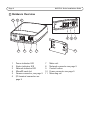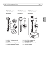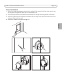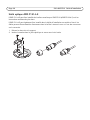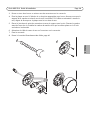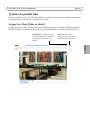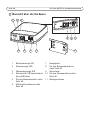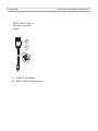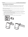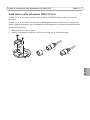
1
INSTALLATION GUIDE AXIS P1204 Network Camera AXIS P1214-E Network Camera DEUTSCH AXIS P1224-E Network Camera FRANÇAIS AXIS P1214 Network Camera ENGLISH AXIS P12 Network Camera Series ITALIANO ESPAÑOL About this Document This document includes instructions for installing AXIS P12 Network Camera series on your network. Previous experience of networking will be beneficial when installing the product. Legal Considerations Video and audio surveillance can be prohibited by laws that vary from country to country. Check the laws in your local region before using this product for surveillance purposes. This product includes one (1) H.264 decoder license. To purchase further licenses, contact your reseller. Trademark Acknowledgments Apple, Boa, Bonjour, Ethernet, Internet Explorer, Linux, Microsoft, Mozilla, Real, SMPTE, QuickTime, UNIX, Windows, Windows Vista and WWW are registered trademarks of the respective holders. Java and all Java-based trademarks and logos are trademarks or registered trademarks of Oracle and/or its affiliates. UPnPTM is a certification mark of the UPnPTM Implementers Corporation. Electromagnetic Compatibility (EMC) This equipment has been designed and tested to fulfill applicable standards for: • Radio frequency emission when installed according to the instructions and used in its intended environment. • Immunity to electrical and electromagnetic phenomena when installed according to the instructions and used in its intended environment. USA - This equipment has been tested using a shielded network cable (STP) and found to comply with the limits for a Class B digital device, pursuant to part 15 of the FCC Rules. These limits are designed to provide reasonable protection against harmful interference in a residential installation. This equipment generates, uses and can radiate radio frequency energy and, if not installed and used in accordance with the instructions, may cause harmful interference to radio communications. However, there is no guarantee that interference will not occur in a particular installation. If this equipment does cause harmful interference to radio or television reception, which can be determined by turning the equipment off and on, the user is encouraged to try to correct the interference by one or more of the following measures: • Reorient or relocate the receiving antenna. • Increase the separation between the equipment and receiver. • Connect the equipment into an outlet on a circuit different from that to which the receiver is connected. • Consult the dealer or an experienced radio/TV technician for help. Canada - This Class B digital apparatus complies with Canadian ICES-003. Europe This digital equipment fulfills the requirements for RF emission according to the Class B limit of EN 55022. This product fulfills the requirements for immunity according to EN 61000-6-1 residential, commercial and light-industrial environments. This product fulfills the requirements for immunity according to EN 55024 residential and commercial environments. Australia - This digital equipment fulfills the requirements for RF emission according to the Class B limit of AS/NZS CISPR 22. Japan - この装置は、クラスB 情報技術装置です。 この装置は、家庭環境で使用することを目 的として いますが、この装置がラジオやテレビジョン受信機 に近接して使用されると、 受信障害を引き起こすこ とがあります。 取扱説明書に従って正しい取り扱い をして下さい。 Korea - ࢇ̛̛Еɼࢽࡈ%̗ࢷળࢶଢ̛̛Ի۰ ࣯Իɼࢽ߾۰ࡈیଜЕʨࡶּࢶࡳԻଜֲֻҘ एࠇ߾۰ࡈیଟܹݡТЬ Safety This product complies with IEC/EN/UL 60950-1, Safety of Information Technology Equipment. The power supply used with this product shall fulfill the requirements for Safety Extra Low Voltage (SELV) and Limited Power Source (LPS) according to IEC/EN/UL 60950-1. AXIS P1214-E/AXIS P1224-E Sensor Unit: This product complies with IEC/EN/UL 60950-1 and IEC/EN/UL 60950-22, Safety of Information Technology Equipment. Equipment Modifications This equipment must be installed and used in strict accordance with the instructions given in the user documentation. This equipment contains no user-serviceable components. Unauthorized equipment changes or modifications will invalidate all applicable regulatory certifications and approvals. Liability Every care has been taken in the preparation of this document. Please inform your local Axis office of any inaccuracies or omissions. Axis Communications AB cannot be held responsible for any technical or typographical errors and reserves the right to make changes to the product and documentation without prior notice. Axis Communications AB makes no warranty of any kind with regard to the material contained within this document, including, but not limited to, the implied warranties of merchantability and fitness for a particular purpose. Axis Communications AB shall not be liable nor responsible for incidental or consequential damages in connection with the furnishing, performance or use of this material. This product is only to be used for its intended purpose. RoHS This product complies with both the European RoHS directive, 2002/95/EC, and the Chinese RoHS regulations, ACPEIP. WEEE Directive The European Union has enacted a Directive 2002/96/EC on Waste Electrical and Electronic Equipment (WEEE Directive). This directive is applicable in the European Union member states. The WEEE marking on this product (see right) or its documentation indicates that the product must not be disposed of together with household waste. To prevent possible harm to human health and/or the environment, the product must be disposed of in an approved and environmentally safe recycling process. For further information on how to dispose of this product correctly, contact the product supplier, or the local authority responsible for waste disposal in your area. Business users should contact the product supplier for information on how to dispose of this product correctly. This product should not be mixed with other commercial waste. Support Should you require any technical assistance, please contact your Axis reseller. If your questions cannot be answered immediately, your reseller will forward your queries through the appropriate channels to ensure a rapid response. If you are connected to the Internet, you can: • download user documentation and firmware updates • find answers to resolved problems in the FAQ database. Search by product, category, or phrases • report problems to Axis support by logging in to your private support area Safeguards Please read through this Installation Guide carefully before installing the Axis product. Keep the Installation Guide for further reference. • • • • • • • This Axis product shall be used in compliance with local laws and regulations. Transportation • When transporting the Axis product, use the original packaging or equivalent to prevent damage to the product. ENGLISH • Store the Axis product in a dry and ventilated environment. Avoid exposing the Axis product to vibration, shocks or heavy pressure. Do not install the product on unstable brackets, unstable or vibrating surfaces or walls, since this could cause damage to the product. Only use applicable tools when installing the Axis product; excessive force could cause damage to the product. Do not use chemicals, caustic agents, or aerosol cleaners. Use a damp cloth for cleaning. Use only accessories that comply with technical specification of the product. These can be provided by Axis or a third party. Use only spare parts provided by or recommended by Axis. Do not attempt to repair the product by yourself, contact Axis or your Axis reseller for service matters. Battery Replacement This Axis product uses a 3.0 V BR2032 or CR2032 lithium battery as the power supply for its internal real-time clock (RTC). Under normal conditions this battery will last for a minimum of 5 years. Low battery power affects the operation of the RTC, causing it to reset at every power-up. A log message will appear when the battery needs replacing. The battery should not be replaced unless required! If the battery does need replacing, please contact www.axis.com/techsup for assistance. • Dispose of used batteries according to the manufacturer's instructions. • • Risk of explosion if battery is incorrectly replaced. Replace only with the same or equivalent battery, as recommended by the manufacturer. AXIS P12 Series Installation Guide Page 5 AXIS P12 Network Camera Series Installation Guide This Installation Guide provides instructions for installing AXIS P12 Network Camera on your network. For all other aspects of using the product, please see the User Manual, available at www.axis.com 1. 2. 3. 4. Check the package contents against the list below. Hardware overview. See page 6. Install the hardware. See page 12 Access the Axis Product. See page 20. Package Contents Item Models/variants/notes Network camera Main unit Sensor unit AXIS P1204/AXIS P1214/AXIS P1214-E/AXIS P1224-E/ Connectors 2-pin power terminal block 4 pin I/O connector terminal block Mounting Accessories All variants: Mounting rail AXIS P1204: Straight mounting bracket, angled mounting bracket, cover AXIS P1214/AXIS P1224-E: Mounting bracket AXIS P1214-E: Mounting bracket, outdoor housing CD Installation and Management Software CD, including installation tools and other software Printed materials AXIS P12 Series Installation Guide (this document) Axis Warranty Document AVHS Authentication key ENGLISH Installation Steps Page 6 AXIS P12 Series Installation Guide Hardware Overview 1 2 3 8 4 1 2 3 4 5 6 5 6 7 Power indicator LED Status indicator LED Network indicator LED MicroSD card slot Camera connector, see page 9 I/O terminal connector see page 9 9 10 11 7 8 9 10 11 Main unit Network connector see page 9 Control button Power connector see page 9 Mounting rail AXIS P12 Series Installation Guide AXIS P1204 sensor unit and included accessories Page 7 AXIS P1214 sensor unit and included accessories 16 18 17 17 13 14 15 19 12 13 14 15 AXIS P1204 sensor unit Cover Straight mounting bracket Angled mounting bracket 16 17 18 19 AXIS P1214 sensor unit Mounting bracket AXIS P1214-E sensor unit Outdoor housing ENGLISH 12 AXIS P1214-E sensor unit and included accessories Page 8 AXIS P12 Series Installation Guide AXIS P1224-E sensor unit and included accessories 20 17 17 Mounting bracket 20 AXIS P1224-E sensor unit AXIS P12 Series Installation Guide Page 9 Connectors Network - RJ45 Ethernet connector. Supports PoE (Power over Ethernet, class 2). Due to local regulations or the environmental and electrical conditions in which the product is to be used, a shielded network cable (STP) may be appropriate or required. Any network cables that are routed outdoors or in demanding electrical environments shall be shielded (STP) and intended for their specific use. Make sure the network switch is properly grounded. See Electromagnetic Compatibility (EMC) for regulatory requirements. ENGLISH Power connector - 2-pin terminal block for power input. Function Pin number Description GND 1 Ground DC Power 2 Power input 8-28 V DC max 4.7 W 1 2 Camera connector - RJ12 connector. I/O terminal connector - Use in applications for e.g. motion detection, event triggering, time lapse recording and alarm notifications. In addition to an auxiliary power and a GND pin, the I/O terminal connector provides 1 2 3 4 the interface to: • Digital output — For connecting external devices such as relays and LEDs. Connected devices can be activated by the VAPIX® Application Programming Interface, output buttons on the Live View page or by an Action Rule. The output will show as active (shown under System Options > Port & Devices > Port Status) if the alarm device is activated. • Digital input — An alarm input for connecting devices that can toggle between an open and closed circuit, for example: PIRs, door/window contacts, glass break detectors, etc. When a signal is received the state changes and the input becomes active (shown under System Options > Port & Devices > Port Status). Function Pin number Notes GND 1 Ground Specifications 3.3 V DC Power 2 Can be used to power auxiliary equipment. Note: This pin can only be used as power out. Max load = 50 mA Input 3 Digital input - Connect to GND to activate, or leave floating (or unconnected) to deactivate. 0 to +40 V DC Output 4 Digital output - Internal connection to ground when activated, floating (unconnected) when deactivated. If used with an external relay, a diode must be connected in parallel with the load, for protection against voltage transients. Max load = 100 mA Max voltage = +40 V DC Page 10 AXIS P12 Series Installation Guide Connection diagram 1 3.3 V max 50 mA 2 3 4 SD card slot - A standard or high-capacity microSD card (not included) can be used for local recording with removable storage. Note: Before removal, the SD card should be unmounted to prevent corruption of recordings. To unmount the SD card, go to Setup > System Options > Storage > SD Card and click Unmount. AXIS P12 Series Installation Guide Page 11 Camera LED Indicators LED Color Indication Network Green Steady for connection to a 100 MBit/s network. Flashes for network activity. Amber Steady for connection to a 10 MBit/s network. Flashes for network activity. Unlit No network connection. Status Steady green for normal operation. Steady during startup and when restoring settings. Red Slow flash for failed upgrade. Unlit No connection between sensor unit and main unit. Green Normal operation. Amber Flashes green/amber during firmware upgrade. Note: The Status and Network LEDs can be configured to be unlit during normal operation. To configure, go to Setup > System Options > Ports & Devices > LED. See the online help for more information. ENGLISH Power Green Amber Page 12 AXIS P12 Series Installation Guide Install the hardware ! IMPORTANT! - The casing of the main unit is not approved for outdoor use - the product may only be installed in indoor environments. Make a note of the serial number (S/N) located on the product label. This number may be required during installation. The main unit for the AXIS P1204/P1214/P1214-E/P1224-E can be mounted on a DIN rail or using the supplied mounting rail. 1. If using the mounting rail, fasten it with screws to the wall or ceiling, using screws and plugs appropriate for the wall/ceiling material. Note the direction of the two tabs on the rail, the tabs align with the upper side of the main unit. 2. Attach the upper end of the main unit to the DIN rail or the mounting rail and snap the lower end into place. 3. Proceed with the instructions for the appropriate camera model below. AXIS P12 Series Installation Guide Page 13 AXIS P1204 Sensor Unit ! IMPORTANT! - The casing of the AXIS P1204 sensor unit is not approved for outdoor use - the product may only be installed in indoor environments. The AXIS P1204 can be mounted in three different ways: flat on any surface angled on any surface, using the angled fastening bracket covertly behind a thin material, for example a metal sheet in a doorpost or an ATM machine. Flat Surface Installation 1. Fasten the camera to the wall or ceiling, using screws and plugs appropriate for the wall/ceiling material. 2. Snap on the cover. 3. Proceed to Connect the cables, on page 19. ENGLISH • • • Page 14 AXIS P12 Series Installation Guide Angled Surface Installation 1. Fasten the angled mounting bracket to the wall or ceiling, using screws and plugs appropriate for the wall/ceiling material. Ensure that the bracket is pointing towards the area to be monitored. 2. Assemble the plate with the screw and align it so the arrows are vertical or horizontal. 3. Fasten the camera to the plate with the two screws. 4. Snap on the cover. 5. Proceed to Connect the cables, on page 19. AXIS P12 Series Installation Guide Page 15 Covert Installation 1. Drill a hole with 3mm diameter in the wall or ceiling. If the material is thicker than 1mm it may be necessary to expand the hole with a countersink cutter. 2. Pull off the protection on the adhesive and attach the straight mounting bracket to the wall. 3. Insert the camera into the bracket, and fasten with the stop screw. Ensure that the cone of the camera is flush with the wall. 4. Proceed to Connect the cables, on page 19. ENGLISH Page 16 AXIS P12 Series Installation Guide AXIS P1214/AXIS P1224-E Sensor Unit ! IMPORTANT! - The casing of the AXIS P1214 sensor unit is not approved for outdoor use - the product may only be installed in indoor environments. The AXIS P1214/AXIS P1224-E can be mounted behind any wall, with just a small opening for the lens, or with the whole lens assembly protruding through the wall. 1. Drill a hole with 20mm diameter in the wall, either completely through the material, or use a countersink cutter to have a smaller opening. 2. Pull off the protection on the adhesive and attach the mounting bracket to the wall. Optionally secure the bracket with two screws through the holes. 3. Insert the camera and tighten the lock ring as shown in the image below. Position the camera so that the flat surface on the thread is vertical or horizontal. 4. Proceed to Connect the cables, on page 19. Lock ring AXIS P12 Series Installation Guide Page 17 AXIS P1214-E Sensor Unit The AXIS P1214-E can be mounted like the AXIS P1214/AXIS P1224-E, see instructions above. The AXIS P1214-E can also be mounted in the supplied outdoor housing. The cables can be routed through the wall directly into the housing, or through one of the punch-outs in the cover. 1. Remove the two screws and the bracket. 2. Insert the camera into the ball joint and fasten with the stop screw. ENGLISH Page 18 AXIS P12 Series Installation Guide 3. Drill a hole through the wall or remove one of the punch-outs in the cover. 4. Fasten the plate to the wall using screws and plugs appropriate for the wall material. Ensure that the camera bracket is pointing towards the area to be monitored. If routing the cable through the wall, align the cut-out in the plate with the hole in the wall. 5. Place the ball in the socket and fasten the bracket with the screws. Aim the camera away from the wall before tightening the screws. Position the camera so that the flat surface on the thread is vertical or horizontal. 6. Route the cable through the wall, or through the punch-out in the cover. 7. Attach the cover. 8. Proceed to Connect the cables, on page 19. AXIS P12 Series Installation Guide Page 19 Connect the cables ENGLISH 1. Optionally connect external input/output devices, e.g. alarm devices. See page 9 for information on the terminal connector pins. 2. Connect the main unit to the network using a shielded network cable. 3. Connect the sensor unit to the main unit. If required, the cable can be shortened. See the User Manual for further information. 4. Connect power, using one of the methods listed below: • PoE (Power over Ethernet, Class 2). If available, this is automatically detected when the network cable is connected. • Connect power via the terminal connector. See page 9 for information on the terminal connector pins. 5. Check that the indicator LEDs indicate the correct conditions. See the table on page 11 for further details. Note that some LEDs can be disabled and may be unlit. Page 20 AXIS P12 Series Installation Guide Access the Axis Product Use the software provided on the Installation and Management Software CD to assign an IP address, set the password and access the video stream. The Live View Page The product’s Live View page appears in your browser. Click Setup to open the product’s Setup pages, which allow you to customize the Axis product. Setup - Provides all the tools for configuring the product to requirements. Help - Displays online help on all aspects of using the camera. AXIS P12 Series Installation Guide Page 21 Resetting to the Factory Default Settings If the Axis product needs to be reset to factory default, follow these steps: 1. 2. 3. 4. Disconnect power. Press and hold the Control button and reconnect power. Keep the Control button pressed for about 15 seconds until the Status indicator flashes amber. Release the Control button. The process is complete after about 1 minute (when the Status indicator turns green). The product has been reset to the factory default settings. The User Manual is available from the Axis Web site at www.axis.com Tip! Visit www.axis.com/techsup to check if there is updated firmware available for your network camera. To see the currently installed firmware version, see Setup > About. Learn more! Visit Axis learning center www.axis.com/academy for useful trainings, webinars, tutorials and guides. Warranty For information about Axis’ product warranty and thereto related information, see www.axis.com/warranty ENGLISH Further Information Mesures de sécurité Lisez attentivement le présent Guide d'installation avant d'installer le produit Axis. Conservez le Guide d'installation pour une utilisation ultérieure. • • • • • • • Ce produit Axis doit être utilisé conformément aux lois et réglementations locales en vigueur. Transport • Pour transporter le produit Axis et éviter de l'endommager, utilisez l'emballage d'origine ou un emballage équivalent. FRANÇAIS • Conservez le produit Axis dans un environnement sec et aéré. Évitez d'exposer le produit Axis aux vibrations, aux chocs ou à une forte pression. N'installez pas le produit sur un support instable, ou des surfaces ou des murs instables ou vibrants, car cela pourrait l'endommager. N'utilisez que les outils applicables pour installer le produit Axis ; une force excessive pourrait endommager le produit. Pour le nettoyage, n’utilisez ni produits chimiques, ni substances caustiques ou aérosols. Utilisez un chiffon humide pour le nettoyage. N’utilisez que des accessoires conformes aux caractéristiques techniques du produit. Ceuxci peuvent être fournis par Axis ou par un fournisseur tiers. Utilisez uniquement des pièces de rechange fournies ou recommandées par Axis. Ne tentez pas de réparer le produit vous-même, contactez Axis ou votre revendeur Axis pour toute réparation. Remplacement des piles Ce produit Axis nécessite une pile au lithium CR2032 ou BR2032 de 3,0 V pour l'alimentation de son horloge en temps réel interne. Dans des conditions normales d'utilisation, cette pile est censée durer au moins 5 ans. Si la pile est faible, le fonctionnement de l'horloge en temps réel peut être affecté et entraîner sa réinitialisation à chaque mise sous tension. Un message enregistré apparaît lorsque la pile doit être remplacée. Ne remplacez la pile qu'en cas de nécessité ! Si la pile doit être remplacée, veuillez contacter www.axis.com/techsup pour obtenir de l’aide. • Jetez les piles usagées conformément aux consignes du fabricant. • • Le remplacement incorrect de la pile peut entraîner un risque d'explosion. Remplacez la pile par une pile identique ou équivalente uniquement, en respectant les recommandations du fabricant. Séríe AXIS P12 Guide d’installation Page 25 Série de caméras réseau AXIS P12 Guide d’installation Ce guide d'installation vous explique comment installer une Caméra réseau AXIS P12 sur votre réseau. Pour tous les autres aspects liés à l'utilisation de ce produit, veuillez consulter le Manuel de l'utilisateur, disponible sur www.axis.com. Procédure d’installation Vérifiez que l’emballage contient bien tous les éléments répertoriés dans la liste ci-dessous. Aperçu du matériel. Reportez-vous à la page 24. Installation du matériel. Reportez-vous à la page 33. Accès au produit Axis. Reportez-vous à la page 41. Contenu du module Élément Modèles/variantes/remarques Caméra réseau Unité principale Unité optique AXIS P1204/AXIS P1214/AXIS P1214-E/AXIS P1224-E Connecteurs Bloc de connexion à 2 broches pour l'alimentation en entrée. Bloc de connexion à 4 broches pour E/S Accessoires de montage Toutes les variantes : Rail de fixation AXIS P1204 : Support de fixation droit, support de fixation oblique, couvercle AXIS P1214/AXIS P1224-E: Support de fixation AXIS P1214-E: Support de fixation, boîtier externe CD Le CD d'installation et de gestion du logiciel, y compris les outils d'installation et au autre logiciel Documentation imprimée Guide d'installation de la série AXIS P12 (le présent document) Document de garantie d’Axis Clé d’authentification AVHS FRANÇAIS 1. 2. 3. 4. Page 26 Séríe AXIS P12 Guide d'installation Vue d’ensemble du matériel 1 2 3 8 4 1 2 3 4 5 6 5 6 7 Voyant DEL d’alimentation Voyant DEL d’état Voyant DEL réseau Emplacement carte SD (carte microSD) Connecteur caméra, voir page 29 Connecteur pour terminaux E/S, voir page 26 9 10 11 7 8 9 10 Unité principale Connecteur réseau, voir page 29 Bouton de commande Connecteur d'alimentation, voir page 29 11 Rail de fixation Séríe AXIS P12 Guide d’installation Unité optique AXIS P1204 et accessoires inclus Page 27 Unité optique AXIS P1214 et accessoires inclus 12 Unité optique AXIS P1214-E et accessoires inclus 16 18 17 17 FRANÇAIS 13 14 15 19 12 13 14 15 Unité optique AXIS P1204 Cache de protection Support de fixation droit Support de fixation oblique 16 17 18 19 Unité optique AXIS P1214 Support de fixation Unité optique AXIS P1214-E Boîtier externe Page 28 Séríe AXIS P12 Guide d'installation Unité optique AXIS P1224-E et accessoires inclus 20 17 17 Support de fixation 20 Unité optique AXIS P1224-E Séríe AXIS P12 Guide d’installation Page 29 Connecteurs Réseau - Connecteur Ethernet RJ45. Prend en charge PoE (alimentation par Ethernet, classe 2). Conformément à la règlementation locale et étant donné les conditions électriques et environnementales dans lesquelles le produit doit être utilisé, un câble réseau blindé (STP) peut convenir, voire être obligatoire. Les câbles réseau acheminés vers l'extérieur ou dans des environnements électriques exigeants doivent être blindés (STP) et destinés à leur usage spécifique. Assurez-vous que le commutateur réseau est correctement mis à la terre. Voir Electromagnetic Compatibility (EMC) pour les exigences liées à la règlementation. Connecteur d’alimentation - Bloc terminal à 2 broches pour l'entrée de courant. Numéro de broche Description GND (Terre) 1 Mise à la terre Alimentation CC 2 Entrée de courant 8-28 V CC max. 4,7 W Connecteur de la caméra - Connecteur RJ12. 1 2 FRANÇAIS Fonction Page 30 Séríe AXIS P12 Guide d'installation Connecteur pour terminaux d’E/S - À utiliser dans les applications pour, par exemple, la détection de mouvement, le déclenchement d'évènement, l'enregistrement image par image et les notifications d'alarmes. Outre une 1 2 3 4 alimentation auxiliaire et une broche GND, le connecteur pour terminaux E/S fournit une interface de : • Sortie numérique : permet de connecter des dispositifs externes, comme des relais ou des DEL. Les dispositifs connectés peuvent être activés par l'Interface de Programmation de l'Application VAPIX®, les boutons de sortie sur la page Vidéo en direct ou par une Règle d'action. La sortie est considérée comme étant active (dans System Options > Port & Devices >Port Status (Options Systèmes > Ports et périphériques > État du port)) si le dispositif d'alarme est activé. • Entrée numérique : entrée d'alarme utilisée pour connecter des dispositifs pouvant passer d'un circuit ouvert à un circuit fermé, par exemple : détecteurs infrarouge passifs, contacts de porte/fenêtre, détecteurs de bris de verre, etc. Lorsqu'un signal est reçu, l'état change et l'entrée devient active (sous System Options > Port & Devices > Port Status (Options Systèmes>Ports et périphériques-État du port)). Fonction Numéro de broche Remarques Caractéristiques techniques GND (Terre) 1 Mise à la terre Alimentation 3,3V CC 2 Peut servir à alimenter le matériel auxiliaire. Remarque : Cette broche ne peut être utilisée que comme sortie d’alimentation. Charge maximale = 50 mA Entrée 3 Entrée numérique : connectez-la à la terre pour l’activer ou laissez-la flotter (ou déconnectée) pour la désactiver. de 0 à +40 V CC Sortie 4 Sortie numérique : connexion interne à la terre lorsqu’activée, flottante (déconnectée) lorsque désactivée. En cas d'utilisation avec un relais externe, une diode doit être connectée en parallèle avec la charge en guise de protection contre les tensions transitoires. Charge max. = 100 mA Tension maximale = +40 V CC Séríe AXIS P12 Guide d’installation Page 31 Schéma de connexion 1 3.3 V max 50 mA 2 3 Logement de la carte SD - Une carte SD standard ou de grande capacité (pas fournie) peut être utilisée pour un enregistrement local sur un stockage amovible. Remarque : Vous devez désinstaller la carte SD avant de la retirer pour éviter que les enregistrements soient corrompus. Pour démonter la carte SD, rendez-vous à Setup > System Options > Storage > SD Card et cliquez sur Démonter. FRANÇAIS 4 Page 32 Séríe AXIS P12 Guide d'installation Voyant DEL de caméra DEL Couleur Indication Réseau Vert Continu en cas de connexion à un réseau de 100 Mbits/s. Clignote en cas d’activité réseau. Orange Continu en cas de connexion à un réseau de 10 Mbits/s. Clignote en cas d’activité réseau. Éteint Pas de connexion réseau. État Alimentation Vert Vert continu en cas de fonctionnement normal. Orange Continu pendant le démarrage ou la restauration des paramètres. Rouge Clignote lentement en cas d’échec de la mise à niveau. Éteint Pas de connexion entre l'unité optique et l'unité principale. Vert Fonctionnement normal. Orange Clignote en vert/orange pendant la mise à niveau du micrologiciel. Remarque : Vous pouvez configurer les voyants d'état et de réseau pour qu'ils soient éteints pendant le fonctionnement normal. Pour ce faire, cliquez sur >Setup > System Options > LED (Configuration - Options système - DEL). Reportez-vous à l'aide en ligne pour plus d'informations. Séríe AXIS P12 Guide d’installation Page 33 Installation du matériel ! IMPORTANT ! – Le boîtier de votre unité principale n’est pas approuvé pour une utilisation extérieure. Le produit doit être uniquement installé en intérieur. Prenez note du numéro de série (S/N) inscrit sur l'étiquette du produit. Ce numéro peut être requis lors de l'installation. L'unité principale de l'AXIS P1204/P1214/P1214-E peut être montée sur un rail DIN ou à l'aide du rail de fixation fourni. FRANÇAIS 1. Si vous utilisez le rail de fixation, fixez le au mur ou au plafond à l'aide de vis. Utilisez des vis ou des prises appropriées pour le mur ou le plafond. Notez la direction des deux attaches sur le rail, elles s'alignent à la partie supérieure de l'unité principale. 2. Fixez l'extrémité supérieure de l'unité principale au rail DIN ou au rail de fixation, et mettez l'extrémité inférieure en place. 3. Continuez avec les instructions ci-après pour le modèle de caméra approprié. Page 34 Séríe AXIS P12 Guide d'installation Unité optique AXIS P1204 ! IMPORTANT ! - Le boîtier de l'unité optique de l'AXIS P1204 n'est pas approuvé pour une utilisation extérieure. Le produit doit être uniquement installé en intérieur. L'AXIS P1204 peut être installée de trois manières différentes : • • • à plat sur toute surface en oblique sur toute surface, à l'aide du support de fixation oblique caché derrière un matériau mince, par exemple une feuille de métal dans un montant de porte ou une machine ATM. Installation sur surface plane 1. Fixez la caméra au mur ou au plafond à l'aide de vis ou de prises appropriées pour le mur ou le plafond. 2. Installez le couvercle. 3. Passez à la section Branchement des câbles, page 40. Séríe AXIS P12 Guide d’installation Page 35 Installation sur surface oblique 1. Fixez le support de montage au mur ou au plafond à l'aide de vis ou de prises appropriées pour le mur ou le plafond. Assurez-vous que le support est orienté vers la zone à surveiller. 2. Assemblez la plaque et la vis et alignez-la de manière à ce que les flèches soient verticales ou horizontales. 3. Fixez la caméra à la plaque à l'aide des deux vis. 4. Installez le couvercle. 5. Passez à la section Branchement des câbles, page 40. FRANÇAIS Page 36 Séríe AXIS P12 Guide d'installation Installation cachée 1. Percez un trou de 3 mm de diamètre dans le mur ou le plafond Si la largeur du matériel est supérieure à 1 mm, il pourrait être nécessaire d'élargir le trou à l'aide d'une fraise. 2. Enlevez la protection de l'adhésif et fixez le support de fixation droit au mur. 3. Insérez la caméra dans le support et serrez avec la vis-butée. S'assurer que le cône de vision de la caméra est au même niveau que le mur. 4. Passez à la section Branchement des câbles, page 40. Séríe AXIS P12 Guide d’installation Page 37 Unité optique AXIS P1214/AXIS P1224-E ! IMPORTANT ! - Le boîtier de l'unité optique de l'AXIS P1214 n'est pas approuvé pour une utilisation extérieure. Le produit doit être uniquement installé en intérieur. L'AXIS P1214 peut être montée derrière tout type de mur, avec juste une petite ouverture pour l'objectif, ou avec l'objectif et sa monture en saillie. l'anneau de serrage FRANÇAIS 1. Percez un trou de 20 mm de diamètre dans le mur, complètement à travers le matériel, ou utilisez une fraise pour obtenir une ouverture plus petite. 2. Enlevez la protection de l'adhésif et fixez le support de fixation au mur. En option, sécurisez l'installation en utilisant deux vis pour maintenir le support. 3. Insérez la caméra et serrez l'anneau de serrage. Installez la caméra de manière à ce que la surface plane sur le fil soit verticale ou horizontale. 4. Passez à la section Branchement des câbles, page 40. Page 38 Séríe AXIS P12 Guide d'installation Unité optique AXIS P1214-E L'AXIS P1214-E peut être installée de la même manière que l'AXIS P1214/AXIS P1224-E, voir les instructions mentionnées plus haut. L'AXIS P1214-E peut également être installé dans le boîtier d'installation en extérieur fourni. Les câbles peuvent être acheminés directement dans le boîtier à travers le mur ou l'une des ouvertures sur le couvercle. 1. Enlevez les deux vis et le support. 2. Insérez la caméra dans le joint sphérique et serrez avec la vis-butée. Séríe AXIS P12 Guide d’installation Page 39 3. Percez un trou dans le mur ou enlevez une des ouvertures sur le couvercle. 4. Fixez la plaque au mur à l'aide de vis ou de prises appropriées pour le mur. Assurez-vous que le support de la caméra est orienté vers la zone à surveiller. Si le câble est acheminé à travers le mur, aligner la découpe sur la plaque avec le trou dans le mur. 5. Placez le joint dans le point de connexion et serrez le support avec les vis. Orientez la caméra avant de serrer les vis. Installez la caméra de manière à ce que la surface plane sur le fil soit verticale ou horizontale. 6. Acheminez la câble à travers le mur ou l'ouverture sur le couvercle. 7. Fixez le couvercle. 8. Passez à la section Branchement des câbles, page 40. FRANÇAIS Page 40 Séríe AXIS P12 Guide d'installation Branchement des câbles 1. Si vous le souhaitez, connectez des dispositifs d’entrée/sortie externes, par exemple des systèmes d'alarme. Reportez-vous à la page 29 pour plus d'informations sur les broches du connecteur pour terminaux. 2. Branchez l'unité principale au réseau à l’aide d’un câble réseau blindé. 3. Connectez l'unité optique à l'unité principale. Au besoin, le câble peut être réduit. Se reporter au Manuel d'utilisation pour plus d'informations. 4. Branchez l’alimentation en suivant l’une des méthodes décrites ci-dessous : • PoE (alimentation par Ethernet, classe 2). Si elle est disponible, elle est automatiquement détectée quand le câble réseau est connecté. • Connexion de l'alimentation via le connecteur pour terminaux. Reportez-vous à la page 29 pour plus d'informations sur les broches du connecteur pour terminaux. 5. Vérifiez que les voyants DEL indiquent que tout fonctionne correctement. Pour plus d'informations, reportez-vous au tableau de la page 32. Notez que certains voyants peuvent être désactivés et donc éteints. Séríe AXIS P12 Guide d’installation Page 41 Accès au produit Axis Utilisez le logiciel fourni sur le CD d'installation et de gestion du logiciel pour attribuer une adresse IP, configurez le mot de passe et accédez au flux vidéo. La page Live View (Vidéo en direct) La page de vidéo en direct s'affiche dans votre navigateur. Cliquez sur Setup (Configuration) pour ouvrir les pages de configuration du produit, qui vous permettent de configurer le produit Axis. Configuration : contient tous les outils nécessaires pour configurer le produit en fonction de vos besoins. Aide : affiche l'aide en ligne sur tout ce qui a trait à l'utilisation de la caméra. FRANÇAIS Page 42 Séríe AXIS P12 Guide d'installation Rétablissement des paramètres d'usine par défaut Si vous devez rétablir le produit aux paramètres d'usine par défaut, procédez comme suit : 1. Débranchez l'alimentation 2. Maintenez le bouton de commande enfoncé et rebranchez l’alimentation. 3. Appuyez sur le bouton de commande pendant environ 15 secondes jusqu’à ce que le témoin d’alimentation passe à l’orange et clignote. 4. Relâchez le bouton de commande. Le processus prend fin après environ 1 minute (lorsque le voyant d’état devient vert). Les paramètres d’usine par défaut du produit ont été rétablis. Plus d’informations Vous pouvez consulter le Manuel de l'utilisateur à l'adresse www.axis.com Conseil : Consultez le site www.axis.com/techsup pour vérifier si des micrologiciels à jour sont disponibles pour votre caméra réseau. Pour connaître la version du micrologiciel actuellement installée, reportez-vous à Configuration > À propos. En savoir plus ! Visitez le centre de formation en ligne d'Axis sur le site www.axis.com/academy pour en savoir plus sur les formations, les webinaires, les tutoriels et les guides. Garantie Pour obtenir plus de renseignements sur la garantie produit AXIS et des renseignements connexes, voir www.axis.com/warranty Sicherheitsvorkehrungen Bitte lesen Sie diese Installationsanleitung sorgfältig durch, bevor Sie mit der Installation des Axis Produkts beginnen. Halten Sie die Installationsanleitung bereit, falls Sie darauf zurückgreifen müssen. • • • • • • • Verwenden Sie dieses Axis-Produkt unter Beachtung der vor Ort geltenden rechtlichen Bestimmungen. Transport • Transportieren Sie das Axis-Produkt nur in der Originalverpackung bzw. in einer vergleichbaren Verpackung, damit das Produkt nicht beschädigt wird. DEUTSCH • Lagern Sie das Axis-Produkt in einer trockenen und belüfteten Umgebung. Setzen Sie das Axis Produkt keinen Vibrationen, Erschütterungen oder starkem Druck aus. Installieren Sie das Produkt nicht an instabilen Halterungen oder instabilen oder vibrierenden Oberflächen oder Mauern, da dadurch das Produkt beschädigt werden könnte. Verwenden Sie bei der Installation des Axis Produkts nur geeignetes Werkzeug; zu hoher Kraftaufwand kann das Produkt beschädigen. Verwenden Sie keine chemischen, ätzenden oder aerosolhaltigen Reinigungsmittel. Verwenden Sie zur Reinigung ein feuchtes Tuch. Verwenden Sie nur Zubehör, das den technischen Spezifikationen des Produkts entspricht. Dieses ist von Axis oder Drittanbietern erhältlich. Verwenden Sie nur Ersatzteile, die von Axis empfohlen bzw. bereitgestellt wurden. Versuchen Sie nicht, das Produkt selbst zu reparieren. Wenden Sie sich bei ServiceAngelegenheiten an Axis oder an Ihren Axis-Händler. Batteriewechsel Dieses Axis-Produkt ist mit einer 3,0 V BR2032 oder CR2032 Lithium-Batterie als Stromversorgung für die interne Echtzeituhr (RTC) ausgestattet. Unter normalen Bedingungen hält die Batterie mindestens 5 Jahre. Bei entladener Batterie ist der Betrieb der Echtzeituhr nicht mehr ausreichend gewährleistet, so dass die Uhr bei jedem Systemstart zurückgesetzt wird. Sie erhalten eine Protokollnachricht, wenn ein Batteriewechsel erforderlich ist. Die Batterie sollte erst bei Bedarf gewechselt werden. Unter www.axis.com/techsup finden Sie Informationen darüber, was Sie beim Austausch der Batterie beachten müssen. • Verbrauchte Batterien sind gemäß den Herstelleranweisungen zu entsorgen. • • Explosionsgefahr bei fehlerhaftem Batteriewechsel! Die Batterie muss durch dasselbe oder ein gleichwertiges Fabrikat ersetzt werden, das vom Hersteller zugelassen ist. Die Serie AXIS P12 Installationsanleitung Seite 45 AXIS P12 Netzwerkkameras Installationsanleitung Diese Installationsanleitung enthält Anweisungen zur Installation AXIS P12 Netzwerkkamera in Ihrem Netzwerk. Alle weiteren Aspekte der Verwendung des Produkts finden Sie im Benutzerhandbuch, das Sie unter www.axis.com abrufen können. Installationsschritte 1 2. 3. 4. Prüfen Sie, ob alle in der nachfolgenden Liste aufgeführten Komponenten vorhanden sind. Übersicht über die Hardware. Siehe Seite 46. Installieren Sie die Hardware. Siehe Seite 52 Ihr Axis Produkt. Siehe Seite 60. Packungsinhalt Modelle/Varianten/Hinweise Netzwerkkamera Hauptgerät Optische Einheit AXIS P1204/AXIS P1214/AXIS P1214-E/AXIS P1224-E Anschlüsse 2-polige Netzklemmleiste 4-polige E/A Anschlussklemmleiste Montagezubehör Alle Varianten: Montageschiene AXIS P1204: Gerade Montagekonsole, Winkelkonsole, Abdeckung AXIS P1214/AXIS P1224-E: Montagekonsole AXIS P1214-E: Montagekonsole, Gehäuse für Montage im Freien CD CD Installations- und Verwaltungssoftware, einschl. Installationstools und anderer Software Gedruckte Dokumente Die Serie AXIS P12 Installationsanleitung (dieses Dokument) Axis-Garantieerklärung AVHS-Authentifizierungsschlüssel DEUTSCH Artikel Seite 46 Die Serie AXIS P12 Installationsanleitung Übersicht über die Hardware 1 2 3 8 4 5 6 7 1 2 Betriebsanzeige LED Statusanzeige LED 3 4 Netzwerkanzeige LED Einschub für SD Speicherkarte (microSD Karte) Für den Kameranschluss siehe Seite 49 E/A Anschlussklemme siehe Seite 49 5 6 9 10 11 7 8 Hauptgerät Für den Netzwerkanschluss siehe Seite 49 9 Steuertaste 10 Für den Stromanschluss siehe Seite 49 11 Montageschiene Die Serie AXIS P12 Installationsanleitung AXIS P1204 Optische Einheit und beigefügtes Zubehör Seite 47 AXIS P1214 AXIS P1214-E Optische Einheit und Optische Einheit und beigefügtes Zubehör beigefügtes Zubehör 12 16 18 17 17 13 14 19 12 13 14 15 AXIS P1204 Optische Einheit Abdeckung Gerade Montagekonsole Winkelkonsole 16 17 18 19 AXIS P1214 Optische Einheit Montagekonsole AXIS P1214-E Optische Einheit Gehäuse für Montage im Freien DEUTSCH 15 Seite 48 Die Serie AXIS P12 Installationsanleitung AXIS P1224-E Optische Einheit und beigefügtes Zubehör 20 17 17 Montagekonsole 20 AXIS P1224-E Optische Einheit Die Serie AXIS P12 Installationsanleitung Seite 49 Anschlüsse Netzwerk - RJ45-Ethernetanschluss. Unterstützt PoE (Power over Ethernet, Klasse 2). Aufgrund der örtlichen Bestimmungen oder der Umgebungs- oder elektrischen Bedingungen, in denen das Produkt eingesetzt werden soll, kann ein abgeschirmtes Netzwerkkabel (STP) angeraten oder erforderlich sein. Alle Netzwerkkabel, die ins Freie oder in komplizierte elektrische Umgebungen geführt werden, sind abzuschirmen (STP) und müssen für den besonderen Einsatz vorgesehen sein. Stellen Sie sicher, dass der Netzwerkschalter ordnungsgemäß geerdet ist. Siehe Electromagnetic Compatibility (EMC) bezüglich der behördlichen Anforderungen. Stromanschluss - 2-polige Klemmenleiste für Stromeingang. Funktion Anschlussnummer Beschreibung Masse (GND) 1 Masse DC (Gleichstrom) 2 Netzeingang 8-28 V DC (Gleichstrom) max. 4,7 W 1 2 E/A Anschlussklemme - Einzusetzen bei Anwendungen wie Bewegungsmeldung, Ereignisauslösung, Zeitrafferaufnahmen und Alarmmeldungen. Außer einem Hilfsspannungs- und GND-Anschluss bietet 1 2 3 4 die E/A Anschlussklemme folgende Schnittstellen: • Digitalausgang – Für den Anschluss von externen Geräten wie Relais und LEDs. Angeschlossene Geräte können über die Schnittstelle zur VAPIX® AnwendungsprogrammSchnittstelle oder über Ausgangstasten auf der Live View Seite oder über eine Aktionsregel aktiviert werden. Der Ausgang erscheint als aktiv (dargestellt unter Systemoptionen > Anschlüsse & Geräte > Portstatus), wenn die Alarmvorrichtung aktiviert ist. • Digitaleingang – Ein Alarmeingang für den Anschluss von Geräten, die zwischen offenem und geschlossenem Schaltkreis wechseln können, zum Beispiel: PIRs, Tür-/Fensterkontakte, Glasbruchdetektoren usw. Wird ein Signal empfangen, ändert sich der Status und der Eingang wird aktiv (dargestellt unter Systemoptionen > Anschlüsse & Geräte > Portstatus). Funktion Anschlussnummer Hinweise Masse (GND) 1 Masse 3,3 V DC (Gleichstrom) 2 Kann für die Stromversorgung von Zusatzgeräten verwendet werden. Hinweis: Dieser Kontakt kann nur für den Stromausgang verwendet werden. Spezifikationen Max. Stromstärke = 50 mA DEUTSCH Kameraanschluss - RJ12 Anschluss. Seite 50 Die Serie AXIS P12 Installationsanleitung Funktion Anschlussnummer Hinweise Spezifikationen Eingang 3 Digitaleingang - Zum Aktivieren mit dem Massekontakt verbinden; zum Deaktivieren schweben lassen (oder nicht anschließen). 0 bis +40 V DC (Gleichstrom) Ausgang 4 Digitalausgang - Interne Verbindung mit Masse, wenn aktiviert, schwebend (nicht angeschlossen), wenn deaktiviert. Zum Schutz vor Überspannungen muss bei der Kombination mit einem externen Relais eine Diode parallel zur Last geschaltet werden. Max. Stromstärke = 100 mA Maximalspannung = +40 V DC (Gleichstrom) Anschlussplan 1 3.3 V max 50 mA 2 3 4 SD-Speicherkarteneinschub - Für Aufzeichnungen vor Ort mit Wechselspeicher kann eine Standard- oder Hochleistungs-microSD Karte (nicht mitgeliefert) verwendet werden. Hinweis: Bevor Sie die SD-Speicherkarte entfernen, müssen Sie diese deaktivieren, um zu verhindern, dass die aufgezeichneten Daten beschädigt werden. Zum Deaktivieren der SD Karte gehen Sie zu Einrichten > Systemoptionen > Speicher > SD Karte und klicken Sie auf Deaktivieren. Die Serie AXIS P12 Installationsanleitung Seite 51 Kamera LED Anzeigen LED Farbe Anzeige Netzwerk Grün Konstant bei Anschluss an ein 100 MBit Netzwerk. Blinkt bei Netzwerkaktivität. Gelb Konstant bei Anschluss an ein 10 MBit Netzwerk. Blinkt bei Netzwerkaktivität. Leuchtet nicht Keine Netzwerkverbindung. Grün Leuchtet bei Normalbetrieb konstant grün. Status Strom Gelb Leuchtet konstant beim Start und der Wiederherstellung der Einstellungen. Rot Blinkt langsam bei Aktualisierungsfehler. Leuchtet nicht Keine Verbindung zwischen Optische Einheit und Hauptgerät. Grün Normaler Betrieb. Gelb Blinkt während der Firmware-Aktualisierung grün/gelb. DEUTSCH Hinweis: Die Status- und Netzwerk-LEDs können so konfiguriert werden, dass sie bei Normalbetrieb nicht leuchten. Zur Konfiguration gehen Sie auf Einrichten > Systemoptionen > Anschlüsse & Geräte > LED. In der Online-Hilfe finden Sie weitere Informationen. Seite 52 Die Serie AXIS P12 Installationsanleitung Installieren Sie die Hardware ! WICHTIG! - Das Gehäuse des Hauptgeräts ist nicht für den Einsatz im Freien zugelassen - das Produkt darf nur im geschlossenen Raum installiert werden. Notieren Sie die Seriennummer (S/N) auf dem Typenschild. Diese kann für die Installation notwendig sein. Das Hauptgerät für die AXIS P1204/P1214/P1214-E kann auf eine DIN Schiene montiert werden oder es wird die mitgelieferte Montageschiene verwendet. 1 Die Montageschiene ist mit Schrauben an Wand oder Decke zu befestigen, wobei Schrauben und Verschlüsse für das Wand-/Deckenmaterial geeignet sein müssen. Achten Sie auf die Ausrichtung der beiden Nasen auf der Schiene, da diese mit der Oberseite des Hauptgeräts korrespondieren müssen. 2. Setzen Sie die Oberseite des Hauptgeräts in die DIN Schiene oder die Montageschiene ein und lassen Sie die Unterseite einrasten. 3. Folgen Sie den folgenden Anweisungen für das entsprechende Kameramodell. Die Serie AXIS P12 Installationsanleitung Seite 53 AXIS P1204 Optische Einheit ! WICHTIG! - Das Gehäuse der optischen Einheit der AXIS P1204 ist nicht für den Einsatz im Freien zugelassen - das Produkt darf nur im geschlossenen Raum installiert werden. Das Gerät AXIS P1204 kann auf drei verschiedene Arten montiert werden: • • • flach auf einer Oberfläche im Winkel auf einer Oberfläche mithilfe der Winkelkonsole verdeckt hinter einem dünnen Material, z.B. hinter einem Metallblech im Türpfosten oder der Front eines Geldautomaten. Installation auf ebener Oberfläche 1 Befestigen Sie die Kamera an der Wand oder Decke mittels Schrauben und Verschlüssen, die für das Wand-/Deckenmaterial geeignet sind. 2. Die Abdeckung aufsetzen und einrasten lassen. 3. Weiter mit Schließen Sie die Kabel an, auf Seite 59. DEUTSCH Seite 54 Die Serie AXIS P12 Installationsanleitung Installation auf Oberfläche im Winkel 1 2. 3. 4. 5. Befestigen Sie die Winkelkonsole an der Wand oder Decke mittels Schrauben und Verschlüssen, die für das Wand-/Deckenmaterial geeignet sind. Stellen Sie sicher, dass die Konsole zu dem zu überwachenden Bereich weist. Montieren Sie die Platte mit der Schraube und richten Sie sie so aus, dass die Pfeile vertikal oder horizontal ausgerichtet sind. Befestigen Sie die Kamera mit den beiden Schrauben an der Platte. Die Abdeckung aufsetzen und einrasten lassen. Weiter mit Schließen Sie die Kabel an, auf Seite 59. Die Serie AXIS P12 Installationsanleitung Seite 55 Verdeckte Installation 1 Bohren Sie ein Loch von 3 mm in Wand oder Decke. Ist das Material stärker als 1 mm, dann muss das Loch eventuell mit einem Halssenker erweitert werden. 2. Ziehen Sie die Schutzfolie von der Klebefläche und drücken Sie die gerade Montagekonsole an der Wand fest. 3. Schieben Sie die Kamera in die Konsole und befestigen Sie sie mit der Sperrschraube. Vergewissern Sie sich, dass der Konus der Kamera bündig mit der Wand ist. 4. Weiter mit Schließen Sie die Kabel an, auf Seite 59. DEUTSCH Seite 56 Die Serie AXIS P12 Installationsanleitung AXIS P1214/AXIS P1224-E Optische Einheit ! WICHTIG! - Das Gehäuse der optischen Einheit der AXIS P1214 ist nicht für den Einsatz im Freien zugelassen - das Produkt darf nur im geschlossenen Raum installiert werden. Die AXIS P1214 kann hinter jeder Wand montiert werden, es muss nur eine kleine Öffnung für die Linse vorhanden sein; auch kann das gesamte Objektivsystem durch die Wand geführt werden. 1 Bohren Sie ein Loch von 20 mm Durchmesser in die Wand, entweder voll durch das Material oder aber mit einem Halssenker, so dass sich eine kleinere Öffnung ergibt. 2. Ziehen Sie die Schutzfolie von der Klebefläche und drücken Sie die Montagekonsole an der Wand fest. Auch kann die Konsole mit zwei durch die Löcher geführten Schrauben gesichert werden. 3. Schieben Sie die Kamera ein und ziehen Sie den Haltering an. Positionieren Sie die Kamera so, dass die ebene Fläche am Gewinde vertikal oder horizontal liegt. 4. Weiter mit Schließen Sie die Kabel an, auf Seite 59. Haltering Die Serie AXIS P12 Installationsanleitung Seite 57 AXIS P1214-E Optische Einheit Die AXIS P1214-E kann ebenso montiert werden wie die AXIS P1214/AXIS P1224-E, siehe Anweisungen oben. Die AXIS P1214-E kann auch im mitgelieferten Gehäuse für Einsätze im Freien montiert werden. Die Kabel können durch die Wand direkt zum Gehäuse geführt werden oder durch eine der ausgestanzten Öffnungen in der Abdeckung. 1 Entfernen Sie die beiden Schrauben und die Konsole. 2. Schieben Sie die Kamera in das Kugelgelenk und befestigen Sie sie mit der Sperrschraube. DEUTSCH Seite 58 Die Serie AXIS P12 Installationsanleitung 3. Bohren Sie ein Loch durch die Wand oder entfernen Sie eine der Ausstanzungen in der Abdeckung. 4. Befestigen Sie die Platte an der Wand mittels Schrauben und Verschlüssen, die für das Wandmaterial geeignet sind. Stellen Sie sicher, dass die Kamera zu dem zu überwachenden Bereich weist. Wenn Sie das Kabel durch die Wand führen, richten Sie den Ausschnitt in der Platte nach dem Loch in der Wand aus. 5. Setzen Sie die Kugel in den Halter und befestigen Sie die Konsole mit den Schrauben. Richten Sie die Kamera von der Wand weg, bevor Sie die Schrauben anziehen. Positionieren Sie die Kamera so, dass die ebene Fläche am Gewinde vertikal oder horizontal liegt. 6. Führen Sie das Kabel durch die Wand oder durch die Ausstanzung in der Abdeckung. 7. Montieren Sie die Abdeckung. 8. Weiter mit Schließen Sie die Kabel an, auf Seite 59. Die Serie AXIS P12 Installationsanleitung Seite 59 Schließen Sie die Kabel an 1 2. 3. 4. 5. Sie können zusätzlich externe E/A-Geräte, wie z. B. Alarmanlagen, anschließen. Siehe Seite 49 bezüglich Informationen zur Belegung der Anschlussklemmen. Schließen Sie das Hauptgerät mittels eines abgeschirmten Netzwerkkabels an das Netzwerk an. Verbinden Sie optische Einheit und Hauptgerät. Wenn nötig, kann das Kabel gekürzt werden. Weitere Informationen finden Sie im Benutzerhandbuch. Schließen Sie die Kamera auf eine der folgenden Arten an die Stromversorgung an: • PoE (Power over Ethernet, Klasse 2). Ist diese Funktion verfügbar, dann wird dies bei Anschluss des Netzwerkkabels automatisch ermittelt. • Über die Anschlussklemme an den Strom anschließen. Siehe Seite 49 bezüglich Informationen zur Belegung der Anschlussklemmen. Überprüfen Sie, ob die LED-Anzeigen die Betriebszustände korrekt angeben. Weitere Details finden Sie in Tabelle Seite 51. Beachten Sie, dass LEDs deaktiviert sein können und deshalb nicht leuchten. DEUTSCH Seite 60 Die Serie AXIS P12 Installationsanleitung Ihr Axis Produkt Verwenden Sie die Software von der Installations- und Verwaltungs-Software CD, um eine IPAdresse zuzuweisen, das Passwort einzustellen und Zugang zum Videostrom zu erhalten. Die Live View Seite Die Live View Seite Ihres Produkts erscheint in Ihrem Browser. Klicken Sie auf Einrichten, um die Seiten zum Einrichten des Produkts zu öffnen. Nun können Sie Ihr Axis Produkt entsprechend einstellen. Einrichten – Bietet alle Tools für die Konfiguration des Produkts entsprechend den Anforderungen. Hilfe – Zum Aufrufen der Online-Hilfe für die Kamera zu allen Aspekten. Die Serie AXIS P12 Installationsanleitung Seite 61 Zurücksetzen auf Werkseinstellung Sollte das Axis Produkt auf Werkseinstellung zurückgesetzt werden müssen, gehen Sie wie folgt vor: 1 2. 3. 4. Vom Stromnetz trennen. Halten Sie die Steuertaste gedrückt und schließen Sie den Netzstecker wieder an. Halten Sie die Steuertaste etwa 15 Sekunden gedrückt, bis die Statusanzeige gelb blinkt. Lassen Sie die Steuertaste los. Der Vorgang ist nach etwa 1 Minute abgeschlossen (die Statusanzeige wird grün). Das Produkt ist nun auf Werkseinstellung zurückgesetzt. Weitere Informationen Das Benutzerhandbuch kann auf der Axis Website unter www.axis.com abgerufen werden. Tipp! Unter „www.axis.com/techsup“ finden Sie Firmware-Aktualisierungen für Ihre NetzwerkKamera. Für die aktuell installierte Firmware-Version siehe Einrichten > Über . Garantie Für weitere Informationen zu der Axis-Produkt-Garantie und zu verwandten Themen, finden Sie unter www.axis.com/warranty DEUTSCH Erfahren Sie mehr! Im Axis Lernzentrum unter www.axis.com/academy finden Sie hilfreiche Schulungen, Webinare, Lernprogramme und Anleitungen. Sicurezza Leggere attentamente questa Guida all'installazione prima di installare un prodotto Axis. Conservare la Guida all'installazione per ulteriori riferimenti. • • • • • • • • Conservare il prodotto Axis in un ambiente asciutto e ben ventilato. Evitare di esporre il prodotto Axis alle vibrazioni, agli urti o a forte pressione. Non installare il prodotto su staffe instabili, superfici o pareti instabili o vibranti, poiché ciò potrebbe danneggiare il prodotto. Utilizzare solo strumenti idonei quando si installa il prodotto Axis. Una forza eccessiva potrebbe danneggiare il prodotto. Non utilizzare sostanze chimiche, agenti caustici o detergenti spray. Utilizzare un panno umido per la pulizia. Utilizzare solo accessori conformi con le specifiche tecniche del prodotto. Queste possono essere fornite da Axis o da terze parti. Utilizzare solo parti di ricambio fornite o raccomandate da Axis. Non tentare di riparare il prodotto da soli, contattare Axis o il rivenditore di zona Axis per assistenza. Questo prodotto Axis deve essere utilizzato in conformità alle leggi e alle disposizioni locali. Trasporto Quando si trasporta il prodotto Axis, utilizzare l'imballo originale o un imballo equivalente per evitare di danneggiare il prodotto. ITALIANO • Sostituzione della batteria Questo prodotto AXIS usa una batteria al litio da 3.0 V CR2032 o BR2032 come fonte di alimentazione per l'orologio real-time interno (RTC). In normali condizioni questa batteria ha una durata di almeno 5 anni. La batteria scarica influisce sul funzionamento dell'RTC, che viene reimpostato ad ogni accensione. Un messaggio di registro apparirà quando la batteria dovrà essere sostituita. La batteria non deve essere sostituita a meno che non sia necessario. Se la batteria non deve essere sostituita, contattare www.axis.com/techsup per assistenza. • Smaltire le batterie usate secondo le istruzioni del produttore. • • Rischio di esplosione se la batteria non viene sostituita correttamente. Sostituire solo con una batteria identica o equivalente, come raccomandato dal produttore. Guida all'installazione della videocamera Serie AXIS P12 Pagina 65 Telecamere di rete serie AXIS P12 Guida all’installazione Questa Guida all'installazione fornisce le istruzioni necessarie per installare Telecamera di rete AXIS P12 nella rete in uso. Per tutte le altre informazioni relative all'uso del prodotto, consultare la Guida per l'utente, disponibile sul sito www.axis.com Procedura di installazione 1. 2. 3. 4. Controllare il contenuto della confezione con l'elenco che segue. Panoramica dell’hardware. Vedere la pagina 66. Installare l’hardware. Vedere la pagina 72. Accesso al prodotto Axis. Vedere la pagina 80. Contenuto della confezione Modelli/varianti/note Telecamera di rete Unità principale Unità Sensore AXIS P1204/AXIS P1214/AXIS P1214-E/AXIS P1224-E Connettori Morsettiera per l'alimentazione a 2 pin Morsettiera connettore I/O a 4 pin Accessori di montaggio Tutte le varianti: Barra per il montaggio AXIS P1204: staffa di montaggio dritta, staffa di montaggio ad angolo, copertura AXIS P1214/AXIS P1224-E: staffa di montaggio AXIS P1214-E: staffa di montaggio, alloggiamento per esterni CD CD Software di installazione e gestione, inclusi gli strumenti di installazione e altro software Materiali stampati Serie AXIS P12 Guida all'installazione (questo documento) Certificato di garanzia Axis Chiave di autenticazione AVHS ITALIANO Elemento Pagina 66 Serie AXIS P12 Guida all'installazione Panoramica dell’hardware 1 2 3 8 4 1 2 3 4 5 6 5 6 7 Indicatore di alimentazione (LED) LED di stato Indicatore di rete (LED) Slot per scheda SD (scheda microSD) Connettore della telecamera, vedere pagina 69 Connettore I/O, Vedere a pagina 69 9 10 11 7 8 Unità principale Connettore di rete vedere pagina 69 9 Pulsante di comando 10 Connettore di alimentazione vedere pagina 69 11 Barra per il montaggio Guida all'installazione della videocamera Serie AXIS P12 AXIS P1204 Unità Sensore e accessori inclusi AXIS P1214 tUnità Sensore e accessori inclusi 12 Pagina 67 AXIS P1214-E Unità Sensore e accessori inclusi 16 18 17 17 13 14 15 19 ITALIANO 12 13 14 15 AXIS P1204 Unità Sensore Copertura Staffa di montaggio dritta Staffa di montaggio ad angolo 16 17 18 19 AXIS P1214 Unità Sensore Staffa di montaggio AXIS P1214-E Unità Sensore Alloggiamento per esterni Pagina 68 Serie AXIS P12 Guida all'installazione AXIS P1224-E Unità Sensore e accessori inclusi 20 17 17 Staffa di montaggio 20 AXIS P1224-E Unità Sensore Guida all'installazione della videocamera Serie AXIS P12 Pagina 69 Connettori Rete - Connettore Ethernet RJ45. Supporto per PoE (Power over Ethernet, classe 2). A causa delle disposizioni locali e delle condizioni ambientali ed elettriche in cui il prodotto deve essere utilizzato, può essere appropriato o necessario un cavo di rete schermato (STP). Qualsiasi cavo di rete installato all'esterno o in ambienti elettrici difficili deve essere schermato (STP) e utilizzato per il proprio uso specifico. Assicurarsi che lo switch di rete sia correttamente collegato a terra. Vedere Electromagnetic Compatibility (EMC) per i requisiti legislativi. Connettore di alimentazione - Morsettiera di alimentazione a 2 pin per ingresso alimentazione. Funzione Numero pin Descrizione GND 1 Terra Alimentazione CC 2 Ingresso alimentazione, 8-28 V CC max 4,7 W 1 2 Connettore della telecamera - Connettore RJ12. Funzione Numero pin Note GND 1 Terra 3.3 Alimentazione V CC 2 Utilizzabile per alimentare apparecchiature ausiliarie. Nota: questo pin può essere usato solo come uscita alimentazione. Specifiche Carico max = 50 mA ITALIANO Connettore per morsetto I/O - Utilizzare in applicazioni come la rilevazione del movimento, l'attivazione degli eventi, la registrazione temporizzata e le notifiche degli allarmi. In aggiunta a un'alimentazione 1 2 3 4 ausiliaria e a un pin GND, il connettore per morsetti I/O fornisce l'interfaccia a: • Uscita digitale - utilizzabile per collegare periferiche esterne come relè e LED. Le periferiche connesse possono essere attivate mediante VAPIX® Application Programming Interface o i pulsanti di controllo nella pagina Live View (Immagini dal vivo) oppure tramite Action Rule (Regola di azione). L'uscita verrà visualizzata come attiva (visualizzata in System Options > Port & Devices > Port Status) (Opzioni di sistema > porte e dispositivi > stato porta) se il dispositivo di allarme è attivato. • Ingresso digitale - ingresso allarme utilizzabile per collegare le periferiche, che può passare dal circuito chiuso al circuito aperto, ad esempio: PIR, contatti porta/finestra, rilevatori di rottura vetri, etc. Dopo la ricezione del segnale lo stato cambia e l’ingresso diventa attivo (visualizzato in System Options > Port & Devices > Port Status) (Opzioni di sistema > porte e periferiche > stato porta). Pagina 70 Serie AXIS P12 Guida all'installazione Funzione Numero pin Note Specifiche Ingresso 3 Ingresso digitale - connettere a GND per l'attivazione o lasciarlo isolato (o scollegato) per disattivarlo. Da 0 a +40 V CC Uscita 4 Uscita digitale - connessione interna con messa a terra quando attiva, isolata (scollegato) quando inattiva. Se utilizzata con un relè esterno, è necessario collegare un diodo in parallelo al carico per proteggere la periferica da transitori di tensione. Carico max. = 100 mA Tensione massima = +40 V CC Schema delle connessioni 1 3.3 V max 50 mA 2 3 4 Slot scheda SD - Una scheda microSD standard o ad alta capacità (non inclusa) può essere utilizzata per registrazioni locali con dispositivi rimovibili. Nota: Prima della rimozione, la scheda SD dovrebbe essere smontata per evitare di danneggiare le registrazioni. Per smontare la scheda SD, andare in Setup > System Options > Storage > SD Card (Opzioni di sistema> archiviazione > scheda SD) e fare clic su Unmount (Smonta). Guida all'installazione della videocamera Serie AXIS P12 Pagina 71 Indicatori LED della telecamera LED Colore Indicazione Rete Verde Luce fissa: connessione di rete a 100 Mbit/s. Luce lampeggiante: attività di rete. Giallo Luce fissa: connessione di rete a 10 Mbit/s. Luce lampeggiante: attività di rete. Stato Alimentazione Spento Nessuna connessione di rete. Verde Luce verde fissa: condizioni di normale utilizzo. Giallo Luce fissa: durante l'avvio e il ripristino delle impostazioni. Rosso Luce lampeggiante lenta: aggiornamento non riuscito. Spento Nessuna connessione tra l'unità Sensore e l'unità principale. Verde Normale utilizzo. Giallo Luce lampeggiante verde/gialla: aggiornamento firmware. Nota: I LED di stato e della rete possono essere configurati per rimanere spenti durante le normali operazioni. Per configurarli, selezionare Setup > System Options > Ports & Devices > LED (Impostazioni > opzioni di sistema > porte e periferiche > LED). Per ulteriori informazioni, consultare la guida in linea. ITALIANO Pagina 72 Serie AXIS P12 Guida all'installazione Installazione dell'hardware ! IMPORTANTE! - L'alloggiamento dell'unità principale non è approvato per l'utilizzo in ambienti esterni. Il prodotto può essere installato soltanto in ambienti interni. Prendere nota del numero seriale (S/N) situato sull'etichetta del prodotto. Il numero è talvolta richiesto durante l’installazione. L'unità principale per la AXIS P1204/P1214/P1214-E può essere montata su una barra DIN o utilizzando la barra di montaggio fornita. 1. Se si utilizza la barra di montaggio, assicurarla al muro o al soffitto con viti e tasselli adeguati al materiale. Fare attenzione alla direzione delle due linguette sulal barra, le linguette si allineano con il lato superiore dell'unità principale. 2. Fissare l'estremità superiore dell'unità principale alla barra DIN o alla barra di montaggio e far scattare l'estremità inferiore in posizione. 3. Procedere di seguito con le istruzioni per il modello di telecamera appropriato. Guida all'installazione della videocamera Serie AXIS P12 Pagina 73 Unità sensore della telecamera AXIS P1204 ! IMPORTANTE! - L'alloggiamento dell'unità sensore della telecamera AXIS P1204 non è approvato per l'utilizzo in ambienti esterni. Il prodotto può essere installato soltanto in ambienti interni. La AXIS P1204 può essere montata in tre modi differenti: • • • piatta su qualsiasi superficie ad angolo su qualsiasi superficie, utilizzando la staffa di fissaggio ad angolo nascosta dietro un materiale sottile, per esempio una lamina di metallo nello stipite di una porta o uno sportello bancomat. Installazione su superficie piatta 1. Assicurare la telecamera a muro o al soffitto, utilizzando viti e tasselli appropriati per il materiale del muro/soffitto. 2. Far scattare la copertura in posizione. 3. Passare a Collegamento dei cavi, a pagina 79. ITALIANO Pagina 74 Serie AXIS P12 Guida all'installazione Installazione su superficie ad angolo 1. Assicurare la staffa di montaggio ad angolo a muro o al soffitto, utilizzando viti e tasselli appropriati per il materiale del muro/soffitto. Assicurarsi che la staffa punti verso l'area da monitorare. 2. Assemblare la piastra con le viti e allinearla in modo che le frecce siano verticali o orizzontali. 3. Assicurare la telecamera alla piastra con le due viti. 4. Far scattare la copertura in posizione. 5. Passare a Collegamento dei cavi, a pagina 79. Guida all'installazione della videocamera Serie AXIS P12 Pagina 75 Installazione nascosta 1. Fare un foro di 3 mm di diametro nel muro o nel soffitto. Se il materiale è più spesso di 1 mm, potrebbe essere necessario allargare il foro con uno svasatore. 2. Rimuovere la protezione sull'adesivo e fissare la staffa di montaggio dritta al muro. 3. Inserire la telecamera nella staffa e assicurarla con la vite di bloccaggio. Assicurarsi che il cono della telecamera sia a livello del muro. 4. Passare a Collegamento dei cavi, a pagina 79. ITALIANO Pagina 76 Serie AXIS P12 Guida all'installazione Unità sensore della telecamera AXIS P1214/AXIS P1224-E ! IMPORTANTE! - L'alloggiamento dell'unità sensore della telecamera AXIS P1214 non è approvato per l'utilizzo in ambienti esterni. Il prodotto può essere installato soltanto in ambienti interni. La AXIS P1214 può essere montata dietro qualsiasi muro, con solo una piccola apertura per l'obiettivo, o con l'intero gruppo obiettivo sporgente dal muro. 1. Fare un foro nel muro di 20 mm di diametro, completamente attraverso il materiale o utilizzare uno svasatore per avere un'apertura più piccola. 2. Rimuovere la protezione sull'adesivo e fissare la staffa di montaggio al muro. Opzionalmente, fissare la staffa con due viti attraverso i fori. 3. Inserire la telecamera e serrare l'anello di bloccaggio. Posizionare la telecamera in modo che la superficie piatta sulla filettatura sia orizzontale o verticale. 4. Passare a Collegamento dei cavi, a pagina 79. l'anello di bloccaggio Guida all'installazione della videocamera Serie AXIS P12 Pagina 77 Unità sensore della telecamera AXIS P1214-E La AXIS P1214-E può essere montata come la AXIS P1214/AXIS P1224-E, vedere le istruzione precedenti. La AXIS P1214-E può essere montata anche nell'alloggiamento per esterni fornito. I cavi possono essere installati attraverso il muro direttamente nell'alloggiamento o attraverso una delle forature presenti nella copertura. 1. Rimuovere le due viti e la staffa. 2. Inserire la telecamera nel giunto a sfera e assicurarla con la vite di bloccaggio. ITALIANO Pagina 78 Serie AXIS P12 Guida all'installazione 3. Effettuare un foro nel muro o rimuovere una delle forature nella copertura. 4. Fissare la piastra al muro utilizzando viti e tasselli appropriati per il materiale del muro. Assicurasi che la staffa della telecamera punti verso l'area da monitorare. Se si installa il cavo attraverso il muro, allineare il ritaglio nella piastra con il foro nel muro. 5. Collocare la sfera nella presa e fissare la staffa con le viti. Puntare la telecamera lontano dal muro prima di stringere le viti. Posizionare la telecamera in modo che la superficie piatta sulla filettatura sia orizzontale o verticale. 6. Installare il cavo attraverso il muro o attraverso la foratura nella copertura. 7. Fissare la copertura. 8. Passare a Collegamento dei cavi, a pagina 79. Guida all'installazione della videocamera Serie AXIS P12 Pagina 79 Collegamento dei cavi 1. Opzionalmente, è possibile collegare periferiche esterne di ingresso/uscita, come i sistemi di allarme. Per informazioni sui pin della morsettiera di alimentazione, vedere la pagina 69 2. Collegare l'unità principale alla rete mediante un cavo di rete schermato. 3. Collegare l'unità sensore all'unità principale. Se necessario, è possibile accorciare il cavo. Per ulteriori informazioni, vedere il Manuale per l'utente. 4. Collegare l'alimentazione mediante uno dei metodi elencati di seguito: • PoE (Power over Ethernet, classe 2). Se disponibile, questo tipo di alimentazione viene automaticamente rilevato al momento della connessione del cavo di rete. • Utilizzare la morsettiera di alimentazione. Per informazioni sui pin della morsettiera di alimentazione, vedere la pagina 69 5. Verificare che i LED indichino le condizioni di funzionamento corrette. Per ulteriori dettagli, vedere la tabella a pagina 71. Si noti che alcuni LED possono essere disabilitati o spenti. ITALIANO Pagina 80 Serie AXIS P12 Guida all'installazione Accesso al prodotto Axis Utilizzare il software fornito nel CD di installazione e gestione per assegnare un indirizzo IP, impostare la password e accedere al flusso video. La pagina Live View La pagina Live View del prodotto viene visualizzata nel browser. Fare clic su Setup (Impostazioni) per aprire le pagine delle impostazioni del prodotto, su cui è possibile personalizzare il prodotto Axis. Setup (Configurazione) - fornisce tutti gli strumenti necessari per configurare il prodotto in base ai requisiti. Help (Aiuto) - visualizza l'aiuto in linea relativo a tutti gli aspetti di utilizzo della telecamera. Guida all'installazione della videocamera Serie AXIS P12 Pagina 81 Ripristino delle impostazioni predefinite di fabbrica Qualora fosse necessario reimpostare il prodotto Axis alle impostazioni predefinite di fabbrica, seguire i seguenti passi: 1. Scollegare l'alimentazione. 2. Tenere premuto il pulsante Control e ricollegare il cavo di alimentazione. 3. Tenere premuto il pulsante Control per circa 15 secondi, fino a quando l'indicatore di stato non lampeggia in giallo. 4. Rilasciare il pulsante Control. Il processo è completo dopo circa 1 minuto (quando l'indicatore di stato diventa verde). Il prodotto è stato reimpostato alle impostazioni di fabbrica predefinite. Ulteriori informazioni La Guida per l'utente è disponibile sul sito Web di Axis all'indirizzo www.axis.com. Suggerimento Visitare il sito di Axis all'indirizzo www.axis.com/techsup per verificare se sono stati pubblicati aggiornamenti per la telecamera di rete. Per conoscere la versione installata del firmware, vedere Setup > About (Impostazioni > informazioni). Ulteriori informazioni Per utili corsi di formazione, webinar, tutorial e guide, visitare il centro di apprendimento di Axis all'indirizzo www.axis.com/academy. Per informazioni sulla garanzia del prodotto Axis e informazioni ad essa relative, consultare la pagina www.axis.com/warranty ITALIANO Garanzia Medidas preventivas Lea detenidamente esta Guía de instalación antes de instalar el producto Axis. Guarde la Guía deinstalación para poder consultarla en el futuro. • • • • • • • • Guarde el producto Axis en un entorno seco y ventilado. Evite exponer el producto Axis a vibraciones, golpes o presiones excesivas. No instale el producto en soportes inestables ni en superficies o paredes inestables o con vibraciones, ya que esto podría dañarlo. Utilice solo las herramientas apropiadas para instalar el producto Axis; una fuerza excesiva podría dañarlo. No utilice productos químicos, agentes cáusticos ni limpiadores en aerosol. Límpielo con un paño húmedo. Utilice solo accesorios que cumplan las especificaciones técnicas del producto. Puede obtenerlos de Axis o de un tercero. Utilice solo piezas de recambio suministradas o recomendadas por Axis. No intente reparar el producto usted mismo, póngase en contacto con Axis o con el distribuidor de Axis para los temas de servicio técnico. Este producto Axis se utilizará de conformidad con la legislación y normativas locales. Transporte • A la hora de transportar el producto Axis, utilice el embalaje original o uno equivalente para no dañar el producto. ESPAÑOL Sustitución de la batería Este producto Axis utiliza la batería de litio 3.0V CR2032 o BR2032 como fuente de alimentación para su reloj en tiempo real ( RTC). En condiciones normales, esta batería durará un mínimo de 5 años. Cuando la batería tiene poca carga, el funcionamiento del RTC se puede ver afectado, ya que esto puede hacer que se reinicie cada vez que se encienda. Aparecerá un mensaje de registro cuando sea necesario sustituir la batería. No se debe sustituir la batería a menos que sea necesario. Si necesita sustituir la batería, visite la página www.axis.com/techsup para recibir asistencia. • Deseche las baterías usadas según las instrucciones del fabricante. • • Existe peligro de explosión si la batería se sustituye de forma incorrecta. Utilice solo baterías de recambio iguales o equivalentes, de acuerdo con las recomendaciones del fabricante. Serie AXIS P12 Guía de instalación Página 85 Serie de cámaras de red AXIS P12 Guía de instalación Esta guía de instalación proporciona las instrucciones necesarias para instalar la Cámara de red AXIS P12 en su red. Para cualquier otra cuestión relativa al uso del producto, consulte el Manual del usuario, disponible en www.axis.com. Pasos para la instalación 1. 2. 3. 4. Comprobación del contenido del paquete cotejándolo con la lista que aparece más adelante. Presentación del hardware. Consulte la página 86. Instalación del hardware. Consulte la página 92. Acceso al producto Axis. Consulte la página 100. Contenido del paquete Modelos/variantes/notas Cámara de red Unidad principal Unidad óptica AXIS P1204/AXIS P1214/AXIS P1214-E/AXIS P1224-E Conectores Bloque de terminales de alimentación de 2 pines Bloque de terminales de conectores de E/S de 4 pines Accesorios de montaje Todas las variantes: carril de montaje AXIS P1204: escuadra de montaje recto, escuadra de montaje inclinado, cubierta AXIS P1214/AXIS P1224-E: escuadra de montaje AXIS P1214-E: escuadra de montaje, carcasa para exteriores CD CD del software de instalación y gestión, que incluye herramientas de instalación y otro software Materiales impresos Guía de instalación de la Serie AXIS P12 (este documento) Documento de garantía de Axis Clave de autenticación AVHS ESPAÑOL Artículo Página 86 Serie AXIS P12 Guía de instalación Presentación del hardware 1 2 3 8 4 5 6 7 1 2 LED indicador de alimentación LED indicador de estado 3 4 LED indicador de red Ranura para tarjetas SD (tarjeta microSD) Conector de cámara; consulte la página 89 Conector de los terminales de E/S; consulte página 89 5 6 9 10 11 7 8 Unidad principal Conector de red; consulte la página 89 9 Botón de control 10 Conector de alimentación: consulte la página 89 11 Carril de montaje Serie AXIS P12 Guía de instalación Unidad óptica AXIS P1204 y accesorios incluidos Página 87 Unidad óptica AXIS P1214 y accesorios incluidos 12 Unidad óptica AXIS P1214-E y accesorios incluidos 16 18 17 17 13 14 15 19 Unidad óptica AXIS P1204 Cubierta Escuadra de montaje recto Escuadra de montaje inclinado 16 17 18 19 Unidad óptica AXIS P1214 Escuadra de montaje Unidad óptica AXIS P1214-E Carcasa para exteriores ESPAÑOL 12 13 14 15 Página 88 Serie AXIS P12 Guía de instalación Unidad óptica AXIS P1214-E y accesorios incluidos 20 17 17 Escuadra de montaje 20 Unidad óptica AXIS P1224-E Serie AXIS P12 Guía de instalación Página 89 Conectores Red - Conector Ethernet RJ45. Admite PoE (alimentación a través de Ethernet, clase 2). Debido a la normativa local o a las condiciones ambientales y eléctricas en las que vaya a utilizar el producto, puede que sea adecuado u obligatorio el uso de un cable de red blindado (STP). Todos los cables de red que se utilicen en exteriores o en entornos eléctricos exigentes deberán estar blindados (STP) y diseñados para su uso específico. Asegúrese de que el conmutador de red disponga de una conexión a tierra adecuada. Consulte los requisitos normativos en la sección Electromagnetic Compatibility (EMC). Conector de alimentación - Bloque de terminales de 2 pines para la entrada de alimentación. Función Número de pines Descripción TIERRA 1 Tierra Alimentación de CC 2 Entrada de alimentación de 8-28 V CC máx. 4,7 W 1 2 Conector de la cámara - Conector RJ12. Función Número de pines Notas TIERRA 1 Tierra 3,3 V CC de alimentación 2 Se puede utilizar para alimentar equipos auxiliares. Nota: este pin solo se puede usar como salida de alimentación. Especificaciones Carga máx. = 50 mA ESPAÑOL Conector de terminales de E/S - Se utiliza en aplicaciones como, p. ej., detección de movimiento, activación de eventos, grabación de secuencias y notificaciones de alarma. Además de una conexión de alimentación auxiliar 1 2 3 4 y un pin a tierra, el conector de terminales de E/S proporciona la interfaz para: • Salida digital: para la conexión de dispositivos externos como relés y LED. Los dispositivos conectados pueden activarse mediante la interfaz de programación de aplicaciones VAPIX®, los botones de salida en la página de visualización en directo o mediante una norma de actuación. La salida se mostrará como activa (en Opciones del sistema > Puertos y dispositivos > Estado del puerto) si el dispositivo de alarma está activado. • Entrada digital: una entrada de alarma para conectar dispositivos que pueden alternar entre un circuito abierto y uno cerrado; por ejemplo: detectores PIR, contactos de puertas y ventanas, detectores de rotura de cristales, etc. Cuando se recibe una señal, el estado cambia y la entrada se activa (se indica en Opciones del sistema > Puertos y dispositivos > Estado del puerto). Página 90 Serie AXIS P12 Guía de instalación Función Número de pines Notas Especificaciones Entrada 3 Entrada digital: conéctela a TIERRA para activarla o déjela suelta (o desconectada) para desactivarla. 0 a +40 V CC Salida 4 Salida digital: conexión interna a tierra cuando está activada, y suelta (desconectada) cuando está desactivada. Si se utiliza con un relé externo, debe conectarse un diodo en paralelo a la carga como protección ante oscilaciones de tensión. Carga máx. = 100 mA Tensión máx. = +40 V CC Diagrama de conexiones 1 3.3 V max 50 mA 2 3 4 Ranura para tarjetas SD - Puede emplearse una tarjeta microSD estándar o de gran capacidad (no incluida) para la grabación local con almacenamiento extraíble. Nota: Antes de retirar la tarjeta SD, hay que desinstalarla para evitar que las grabaciones resulten dañadas. Para extraer la tarjeta SD, vaya a Configuración>Opciones del sistema>Almacenamiento> Tarjeta SD y haga clic en Desinstalar. Serie AXIS P12 Guía de instalación Página 91 Indicadores LED de cámara LED Color Indicación Red Verde Fijo para indicar la conexión a una red de 100 Mbits/s. Parpadea para indicar actividad en la red. Ámbar Fijo para indicar la conexión a una red de 10 Mbits/s. Parpadea para indicar actividad en la red. Apagado No hay conexión de red. Estado Alimentación Verde Verde fijo para indicar funcionamiento normal. Ámbar Fijo durante el arranque y al restablecer la configuración. Rojo Parpadeo lento si no se puede realizar una actualización. Apagado Sin conexión entre la unidad óptica y la unidad principal. Verde Funcionamiento normal. Ámbar Parpadea en verde/ámbar durante la actualización del firmware. Nota: Los LED de estado y red se pueden configurar para que se queden apagados durante el funcionamiento normal. Para realizar esta configuración, vaya a Configuración > Opciones del sistema > Puertos y dispositivos > LED. Para obtener más información, consulte la ayuda en línea. ESPAÑOL Página 92 Serie AXIS P12 Guía de instalación Instalación del hardware ! IMPORTANTE: la carcasa de la unidad principal no está aprobada para su uso en exteriores; el producto solo se puede instalar en interiores. Anote el número de serie (S/N) que aparece en la etiqueta del producto. Es posible que lo necesite durante la instalación. La unidad principal de la AXIS P1204/P1214/P1214-E se puede montar en un carril DIN o mediante el carril de montaje proporcionado. 1. Si usa el carril de montaje, fíjelo a la pared o al techo mediante tornillos y tacos adecuados para el material del que esté hecho la pared o el techo. Tenga en cuenta la dirección de las dos lengüetas del raíl; las lengüetas se alinean con el lado superior de la unidad principal. 2. Conecte el extremo superior de la unidad principal al carril DIN o al carril de montaje y coloque el extremo inferior en su sitio. 3. Continúe con las instrucciones para el modelo de cámara adecuado que se muestran a continuación. Serie AXIS P12 Guía de instalación Página 93 Unidad óptica AXIS P1204 ! IMPORTANTE: la carcasa de la unidad óptica AXIS P1204 no está aprobada para su uso en exteriores; el producto solo se puede instalar en interiores. La AXIS P1204 se puede montar de tres formas distintas: • • • plana sobre cualquier superficie inclinada sobre cualquier superficie mediante la escuadra de montaje inclinado de forma encubierta tras un material delgado como, por ejemplo, una lámina metálica en la jamba de una puerta o en un cajero automático. Instalación en una superficie plana 1. Fije la cámara a la pared o al techo con los tornillos y tacos adecuados para el material del que esté hecho la pared o el techo. 2. Coloque la cubierta. 3. Siga con Conexión de los cables, en la página 99. ESPAÑOL Página 94 Serie AXIS P12 Guía de instalación Instalación en una superficie inclinada 1. Fije la escuadra de montaje inclinado a la pared o al techo con los tornillos y tacos adecuados para el material del que esté hecho la pared o el techo. Asegúrese de que la escuadra apunte hacia la zona que se vaya a supervisar. 2. Monte la placa con el tornillo y alinéela de modo que las flechas estén verticales u horizontales. 3. Fije la cámara a la placa con los dos tornillos. 4. Coloque la cubierta. 5. Siga con Conexión de los cables, en la página 99. Serie AXIS P12 Guía de instalación Página 95 Instalación encubierta 1. Perfore un orificio de 3 mm de diámetro en la pared o el techo. Si el material tiene un grosor superior a 1 mm, puede que sea necesario ensanchar el orificio con un avellanador. 2. Retire la protección del adhesivo y fije la escuadra de montaje recto en la pared. 3. Introduzca la cámara en la escuadra y utilice el tornillo de retención para su fijación. Asegúrese de que el cono de la cámara esté a ras de a la pared. 4. Siga con Conexión de los cables, en la página 99. ESPAÑOL Página 96 Serie AXIS P12 Guía de instalación Unidad óptica AXIS P1214/AXIS P1224-E ! IMPORTANTE: la carcasa de la unidad óptica AXIS P1214 no está aprobada para su uso en exteriores; el producto solo se puede instalar en interiores. La AXIS P1214 puede montarse tras cualquier pared con solo una pequeña apertura para la lente o con todo el conjunto de la lente sobresaliendo de la pared. 1. Perfore un orificio de 20 mm de diámetro en la pared de modo que atraviese totalmente el material, o utilice un avellanador para tener una apertura más pequeña. 2. Retire la protección del adhesivo y fije la escuadra de montaje en la pared. De forma opcional, fije la escuadra con dos tornillos en los orificios. 3. Introduzca la cámara y apriete el anillo de bloqueo. Coloque la cámara de tal modo que la superficie plana de la rosca esté vertical u horizontal. 4. Siga con Conexión de los cables, en la página 99. anillo de bloqueo Serie AXIS P12 Guía de instalación Página 97 Unidad óptica AXIS P1214-E La AXIS P1214-E puede montarse igual que la AXIS P1214/AXIS P1224-E; consulte las instrucciones proporcionadas previamente. La AXIS P1214-E también puede montarse en la carcasa para exteriores proporcionada. Los cables se pueden pasar por la pared directamente hasta el interior de la carcasa o a través de uno de los orificios troquelados de la cubierta. 1. Retire los dos tornillos y la escuadra. 2. Introduzca la cámara en la junta esférica y utilice el tornillo de retención para su fijación. ESPAÑOL Página 98 Serie AXIS P12 Guía de instalación 3. Perfore un orificio a través de la pared o extraiga el material de uno de los orificios troquelados de la cubierta. 4. Fije la placa a la pared con los tornillos y tacos adecuados para el material de la pared. Asegúrese de que la escuadra de la cámara apunte hacia la zona que se haya de supervisar. Si va a pasar el cable a través de la pared, alinee el orificio troquelado de la placa con el orificio de la pared. 5. Coloque la bola en el conector y apriete la escuadra con los tornillos. Apunte la cámara lejos de la pared antes de apretar los tornillos. Coloque la cámara de tal modo que la superficie plana de la rosca esté vertical u horizontal. 6. Pase el cable a través de la pared o a través del orificio troquelado de la cubierta. 7. Fije la cubierta. 8. Siga con Conexión de los cables, en la página 99. Serie AXIS P12 Guía de instalación Página 99 Conexión de los cables 1. También puede conectar dispositivos externos de entrada y salida, como por ejemplo, dispositivos de alarma. Para obtener más información sobre los pines de los conectores de terminales, consulte la página 89. 2. Conecte la unidad principal a la red mediante un cable de red blindado. 3. Conecte la unidad óptica a la unidad principal. Si fuese necesario, el cable se puede acortar. Para obtener más información, consulte el Manual del usuario. 4. Conecte la alimentación mediante uno de los métodos especificados a continuación: • PoE (alimentación a través de Ethernet, Clase 2). Si está disponible, se detectará automáticamente al conectar el cable de red. • Conecte la alimentación mediante el conector de terminales. Para obtener más información sobre los pines de los conectores de terminales, consulte la página 89. 5. Compruebe que los indicadores LED indican las condiciones adecuadas. Para obtener información más detallada, consulte la tabla de la página 91. Tenga en cuenta que algunos LED pueden deshabilitarse y apagarse. ESPAÑOL Página 100 Serie AXIS P12 Guía de instalación Acceso al producto Axis Utilice el software suministrado en el CD del software de instalación y gestión para asignar una dirección IP, establecer la contraseña y acceder a la transmisión de vídeo. La página Visualización en directo La página Visualización en directo del producto aparece en su navegador. Haga clic en Configuración para abrir las páginas de configuración del producto, que le permiten personalizar el producto Axis. Configuración: proporciona todas las herramientas necesarias para configurar el producto según sus necesidades. Ayuda: muestra ayuda en línea sobre todos los aspectos del uso de la cámara. Serie AXIS P12 Guía de instalación Página 101 Restablecimiento de la configuración predeterminada de fábrica Si es necesario restablecer los valores de fábrica del producto Axis, siga los pasos indicados a continuación: 1. Desconecte la alimentación. 2. Mantenga pulsado el botón de control y vuelva a conectar la alimentación. 3. Mantenga pulsado el botón de control durante 15 segundos hasta que el indicador de estado parpadee en color ámbar. 4. Suelte el botón de control. El proceso finalizará aproximadamente 1 minuto después (cuando el indicador de estado se ilumine en color verde). Se ha restablecido la configuración predeterminada de fábrica del producto. Más información El Manual del usuario está disponible en el sitio web de Axis en www.axis.com. Consejo: Visite www.axis.com/techsup para comprobar si hay disponible firmware actualizado para su cámara de red. Para ver la versión de firmware actualmente instalada, consulte Configuración > Acerca de. Más información: Visite el centro de formación de Axis en www.axis.com/academy para consultar cursos, seminarios web, tutoriales y guías de gran utilidad. Garantía ESPAÑOL Para obtener más información acerca de la garantía de los productos Axis e información relacionada, visite www.axis.com/warranty Installation Guide AXIS P12 Network Camera Series © Axis Communications AB, 2010-2014 Ver.2.1 Printed: May 2014 Part No. 57678