1
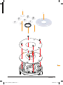
e) Maintain power tools. Check for misalignment or
binding of moving parts, breakage of parts and
any other condition that may affect the power
tool’s operation. If damaged, have the power tool
repaired before use. Many accidents are caused by
poorly maintained power tools.
f) Keep cutting tools sharp and clean. Properly
maintained cutting tools with sharp cutting edges are
less likely to bind and are easier to control.
g) Use the power tool, accessories and tool bits etc.
in accordance with these instructions, taking into
account the working conditions and the work to
be performed. Use of the power tool for operations
different from those intended could result in a
hazardous situation.
5) Service
a) Have your power tool serviced by a qualified repair
person using only identical replacement parts.
This will ensure that the safety of the power tool is
maintained.
INSTALLATION
FITTING THE GUIDE PLATE
• To use the Guide Bushes (A – G) for template routing,
you must first fit the Guide Plate (2) to the base of your
Triton router
Preparing the Guide Plate
1. Loosely fit the two M4 Screws (3) into the holes in the
depressed side of the Guide Plate (2), leaving a 3mm
gap under each head
2.Place the Alignment Bush (1), recessed side up, in
the centre of the Guide Plate (2) with the two notches
aligned with the screw heads
3.Rotate the Alignment Bush (1) until the notches no
longer align with the screw heads, then tighten the
screws to secure the Alignment Bush (1) to the Guide
Plate (2)
Preparing the router
1. Turn the Triton router upside down and plunge it to the
collet lock position
2.Unscrew the four Phillips head screws which secure
the black baseplate, then remove the baseplate
Attaching the Guide Plate
1. With the threads of the M4 screws (3) facing into the
router, position the Guide Plate (2) over the router
collet and on to the router base
2.Align all the fixing holes in the Guide Plate (2)
with those in the router base, then re-fit the black
baseplate
3.Secure the assembly in position using the four Phillips
head screws. Do not over-tighten as this can distort
the baseplate
2.Loosen the two M4 Screws (3), remove the Alignment
Bush (1) and in its place fit the required Guide Bush
(A – G). Fit the guide bush with its collar side up,
pointing away from the body of the router
3.Rotate the cutter by hand to ensure there is complete
clearance between the cutter and the guide bush
Porter Cable Guide Bush
• To fit a Porter Cable guide bush:
1. Loosen the M4 Screws (3) and remove the Alignment
Bush (1) from the Guide Plate (2)
2.Fit the Porter Cable Bush Adaptor (1) into the recessed
side of the Alignment Bush (1)
3.Fit this assembly to the Guide Plate (2)
TABLE-MOUNTED USE
• The Table Spacer (4) is required when template routing
on a router table
1. Remove the insert ring from your router table
2.Remove the M4 Screws (3) and Alignment Bush (1)
from the Guide Plate (2) and sit the Table Spacer (4),
recessed side up, into the centre of the Guide Plate (2)
3.Align the screw holes, then fit the screws and the
required Guide Bush (A – G).
REMOVING THE GUIDE PLATE
• Even when not using the template guides, the Guide
Plate (2) can remain fitted to the router for the majority
of cuts, whether using the router hand-held or tablemounted
• Remove the Guide Plate (2) when using cutters with a
diameter greater than 50mm (2")
GB
FITTING A GUIDE BUSH
1. Fit a cutter in the router collet and adjust the plunge
until the cutter is hidden
General Safety Instructions / Installation 5
TGA001_MANUAL_AMEND.indd 5
23/08/2012 14:12