1
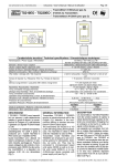
Istruzione / User’s Manual / Manuel d’utilisation
IST-2293.EA01.01
BS-393
TS293EA
TS-293EA
Pag.1/6
(I-ATEX_TS293EA.doc)
Trasmettitore 4÷20mA per Ammoniaca
4÷20mA transmitter for Ammonia
Trasmetteur 4÷20mA pour Ammoniac
Caratterizzati dal modo di protezione
Have the following protection rate
Sont caractérisés par le mode de protection suivant
II 2G EEx d IIC T6
Numero di Certificazione
Certificate number
Numéro du certificat
CESI 03 ATEX 323
Caratteristiche tecniche / Technical specifications / Caractéristiques techniques
Alimentazione / Power supply / Alimentation
Uscita / Output / Sortie
Campo di misura / Standard range / Champ de mesure
Massimo sovraccarico / Max overload / maximum surcharge
Ripetibilità / Repeatability / Répétitivité
Tempo di risposta T50 / Response time T50 / Temps de résponse
T50
Deriva a lungo termine in aria pulita
Long time drift in pure air / Dérive à long terme en air non pollué
Vita media in aria pulita
Expected life in pure air / Durée de vie moyenne en air non pullué
Temp./umidità di funzionamento
Operation Temp./Humidity / Température et humidité de fonctionnement
Temp./umidità di immagazzinamento
Storage Temp./Humidity / Température et humidité de stockage
Variazione dello Zero / Zero Shift / Dérive du Zero
Dimensioni / Size / Dimensions
I
12÷24Vdc (-10/+15%)
4÷20mA Lineare / Linear / Linéaire
0 ÷ 300ppm
1000ppm
± 10 %
< 30 secondi / seconds / secondes
<20% anno
<20% year / <20% an
18 mesi / month / mois
-10 ÷ +40 °C / 5÷90 % r.h. 40°C
+5 ÷ +20°C / 5÷95 % r.h.
<15ppm
190 x 105 x 83 mm
DESCRIZIONE ............................................................................................................................ 2
FUNZIONAMENTO ................................................................................................................................. 2
INSTALLAZIONE.................................................................................................................................... 2
AVVERTENZE ........................................................................................................................................ 2
VERIFICA E/O CALIBRAZIONE............................................................................................................. 3
GB
DESCRIPTION ............................................................................................................................ 3
OPERATIONAL DESCRIPTION ............................................................................................................. 3
INSTALLATION ...................................................................................................................................... 3
WARNING............................................................................................................................................... 4
Calibration and/or Verification ............................................................................................................. 4
F
DESCRIPTION ............................................................................................................................ 5
FONCTIONNEMENT .............................................................................................................................. 5
INSTALLATION ...................................................................................................................................... 5
AVVERTISSEMENT................................................................................................................................ 5
Vérification et/ou Étalonnage ............................................................................................................... 5
TECNOCONTROL S.r.l. - Via Miglioli, 47 20090 SEGRATE (MI)
Tel. 02/26922890 - Fax 02/2133734
http: www.tecnocontrol.it
e-mail: [email protected]
IST-2293.EA01.01
Istruzione / User’s Manual / Manuel d’utilisation
Pag.3/6
VERIFICA E/O CALIBRAZIONE
Si consiglia d'eseguire la verifica di funzionamento e/o la taratura ogni 6/12 mesi. Il gas da utilizzare deve essere
una miscela compresa tra 200 e 300 ppm di NH3 e il resto da Azoto.
Avvertenze: La verifica e/o calibrazione devono essere effettuate solo in condizioni d'aria pulita e dopo che il trasmettitore è rimasto alimentato continuamente per almeno 8 ore. Inoltre devono essere eseguite solo da personale
addestrato e autorizzato. La regolazione dei trimmer va effettuata con un cacciavite d’adeguata dimensione.
“Regolazione dello “ZERO” Aprire il coperchio della custodia. Collegare un multimetro digitale (scala 20 mA) in
serie all'alimentazione. (Importante: scollegando il filo, vengono attivati i relè di allarme e di guasto della centrale a
cui il trasmettitore è collegato).
Attendere circa 5 minuti per permettere al Trasmettitore di stabilizzarsi, quindi verificare che in aria pulita il valore
letto sia 4 mA (±0,5). Nel caso non si riscontrasse tale valore, solo se necessario, regolare il trimmer P1 "ZERO" a
4 mA.
Attenzione: verificare che nell'ambiente non ci siano gas tossici. In caso di dubbio, si consiglia d’utilizzare una
bombola di aria sintetica o aria/ossigeno 20,9%O2. Collegare il Tester di Calibrazione alla bombola (Fig.4) ed infilarlo sul sensore. Aprire il rubinetto della bombola in modo che l'indicatore di flusso sia tra le due tacche (0,2÷0,3
l/min), attendere circa 5 minuti, quindi verificare che i multimetro indichi 4 mA (±0,2mA). Nel caso non si riscontrasse tale valore regolare lentamente, il trimmer P1 "ZERO" a 4 mA.
“Regolazione del Fondo Scala” Collegare il Tester di Calibrazione alla bombola di NH3 ed infilarlo sul sensore
(Fig.4). Aprire il rubinetto della bombola in modo che l'indicatore di flusso sia tra le
16 x (concentrazione gas)
+4
due tacche (0,2÷0,3 l/min), attendere circa 3÷5 minuti, poi verificare che il multi- m A=
cam po di m isura
metro indichi :
Esempio: se il gas della bombola è 245 ppm e il campo di misura del Trasmettitore è 300ppm, i mA corrispondenti sono 17,06 mA come indicato:
m A=
16x245
+ 4 =1 7 ,0 6
300
Regolare molto lentamente e solo se necessario, il trimmer P2 "SPAN" al valore in mA richiesto, togliere il Tester di
Calibrazione, attendere 5÷10 minuti e verificare che il multimetro indichi 4 mA. Scollegare il multimetro e richiudere
il coperchio della custodia.
GB DESCRIPTION
The TS293EA consists of a two-wire 4÷20mA linear transmitter able to detect Ammonia (NH3).
The Ammonia (NH3) is a colourless gas with a very sharp smell. A concentration of 50÷100 ppm causes irritation
of the respiratory system; beyond a concentration of 100ppm it causes eyes irritation. At 5,000 ppm the Ammonia
is lethal.
Its density as to air is 0.6, therefore it is lighter than air and it normally spreads upwards in the environment. Its LEL
(Lower Explosivity Limit) is 15% v/v. The TWA is 25 ppm and the STEL is 35 ppm an “electrochemical” sensor calibrated in ppm NH3.
The instrument comprises of a certified enclosure in which the electronic circuit and the connecting terminals are
mounted. This unit has a downward facing cylindrical section housing the sensor behind a sintered stainless steel
flame trap. The TS293EA is designed to be connected to TECNOCONTROL gas detecting central systems.
OPERATIONAL DESCRIPTION
The sensitive element used is an “electrochemical” sensor. The calibration is carried out with Ammonia.
When powered, the sensor the sensor is able to detect gas even if it attains the optimum stability conditions after
about 48 hours continual functioning. After that time we advise to check in clean air the “4mA” output. If necessary
the “4mA calibration” can be carried out as explained on page 6. This calibration is necessary to adjust the sensor
to the environment conditions.
Faults: In case of failure, the "S" output falls down to 0mA (FAULT). The signal is then indicated as a damage
situation. The same happens also when an interruption to the connection wires between the sensor and the detector occurs.
Average life: The sensitive element used in this type of sensor has an excellent stability in time. In fresh air and in
normal working condition the sensor's life should be about 18 month from the date of the installation.
Periodical testing: we advise to carry out working tests every six months. After 1 year, we advise to proceed to
the circuit recalibration with Gas/Air mixture, as explained on page 4.
INSTALLATION
The TS293EA is designed for standard two-wire operation where the output is supplied via the same wire pair as
the power supply.
The max load resistance (RLMax) will be the sum of the central system input impedances (RL) and the connection
wire total resistance (going and return) (see Fig. 1).
TECNOCONTROL S.r.l. Via Miglioli 47 SEGRATE ( MI )
Tel: 02/26 92 28 90 Fax: 02/21 33 734
IST-2293.EA01.01
Istruzione / User’s Manual / Manuel d’utilisation
Pag.4/6
To calculate the RLmax refer both to the diagram of Fig. 3 and to the following RLmax =(Power Supply Voltage -10) x 1000
20
formula:
RLmax =
As an example, the RLMax of a 24 Vdc Power Supply will be what follows:
(24 - 10) x 1000
= 700 Ohm
20
To this purpose, it is recommended to use a shielded wire.
The Table below shows the average resistance of some wires depending on their section:
Section
Resistance
2 x 0,75mm2
26Ohm/Km
2 X 1 mm2
20 Ohm/Km
2x1,5mm2
14 Ohm/Km
2x2,5mm2
8 Ohm/Km
Positioning: The TS293EA must be installed in the vertical position with the sensor housing placed downward.
Normally the transmitter should be installed at about 30÷50cm from the ceiling to protect people from the Ammonia
toxicity. Wall-mount the unit by two screw anchors.
Electric connections: are to be carried out using the three-pole terminal (See special instructions enclosed with
the gas detectors). It is not necessary to use shielded cables.
Transmitters can be mounted at a max. distance of 300 meters from the gas detector when 3x1.5mm2 cables are
used, and 600 meters with 3x2.5 mm2 cables. (With 12Vdc gas detectors power supply output).
WARNING
Warning: When the transmitter is powered for the first time of after a long time inactivity, the sensor needs about
10-30 seconds to be reset to the normal operational conditions.
Cross-sensitivity: A cross-sensitivity phenomenon with other gases may occur (see Table 1).
IMPORTANT WARNING: in case of alarm situation, owing to an Ammonia leakage, it have to be
always checked the sensor working, as indicated in this page. If the Ammonia concentration is
higher than full scale (300ppm), it could be necessary to replace the sensor.
Calibration and/or Verification
We advise to carry out working testing and/or calibration, every 6/12 months. The gas to use should be a mixture
of 200 to 300 ppm Ammonia and the rest of Nitrogen.
Warnings: The calibration routine is to be carried out only in clean air and after about 8 hour’ instrument continual
working. Any calibration routines are to be carried out by trained or authorised personnel only. For the trimmer adjustment, a suitable-sized screwdriver should be used.
“Zero Calibration”: Open the housing cover, and then connect a digital multimeter (20mA scale) in-series to the
Power Supply. (Important: by disconnecting the loop, the Alarm and Fault relays of the central system the transmitter is connected to will activate).
Wait for about five minutes to allow the transmitter to get a steady condition. When in fresh air, the value to read
should be 4mA (±0.5). If the readout is not 4mA, only if necessary, adjust the P1 “ZERO” trimmer to get 4mA.
Warning: Be sure that there are not toxic gases in the environment. In case of doubt, you should execute either
the 4mA verification using an air/20.9% O2 gas bottle or a synthetic/air gas bottle with the Calibration Tester. Connect the Calibration Tester to the gas bottle (see Fig.4) and insert it on the sensor. Open the gas bottle reducer
cock so as the flow meter is between the two stamps (about 0.2-0.3 l/m). Wait for about 5 minutes, and then check
the value on the multimeter is 4 mA (± 0.2 mA).
“Full scale calibration”: Connect the Calibration Tester to the NH3 gas bottle and insert it on the Sensor (see
Fig.4). Open the gas bottle reducers cock so as the flow indicator is between the two stamps (0.2÷0.3 l/m). Wait for
about 3 to 5 minutes. Then check the value on the multimeter corresponds to
16 x (gas concentration)
mA =
+4
the value calculated following the formula here below:
trnsmitter range
Example: if the gas bottle is 245ppm and the transmitter range is 300ppm,
the corresponding mA value will be as follows:
mA
=
16x245
+ 4 = 17,06
300
If necessary, adjust the P2 “SPAN” trimmer to the required mA value. Remove the Calibration Tester. Wait again
for about 5 to 10 minutes, and then check the digital multimeter shows 4 mA. Disconnect the digital multimeter,
connect the wire and place again the instrument box cover
TECNOCONTROL S.r.l. Via Miglioli 47 SEGRATE ( MI )
Tel: 02/26 92 28 90 Fax: 02/21 33 734
Istruzione / User’s Manual / Manuel d’utilisation
IST-2293.EA01.01
Pag.6/6
“Réglage du “Zéro”. Ouvrir le couvercle du boîtier. Raccorder un multimètre (échelle 20 mA) en série à
l’alimentation. (Important: la decon-nexion du fil entraîne l’activation des relais d’alarme et de dérangement de la
centrale à laquelle la sonde est reliée).
Attendre environ 5 minutes pour permettre au capteur de se stabiliser et vérifier qu’en pair pur la valeur lue est 4
mA (±0,5). Si la valeur obtenue est différente, régler le potentiomètre P1 “ZÉRO” à 4 mA.
Attention: Vérifier que dans l’ambiance il n’y a pas la présence de gaz toxiques. S’il y a des doutes l’on conseille
d’effectuer la vérification du 4mA avec le kit d’étalonnage raccordé à une bouteille d’air synthétique ou air /oxygène
20,9% O2 (Fig.4). Raccorder le kit d’étalonnage à la bouteille et au capteur. Le gaz afflue au capteur avec débit de
0,2÷0,3 l/min, attendre eviron 5 minutes et vérifier que la valeur lue sur le multimètre est 4mA (± 0,2 mA).
Réglage du Fond d’échelle: Raccorder le kit d’étalonnage à la bouteille de NH3
et au capteur. Le gaz afflue au capteur avec débit de 0,2÷0,3 l/min, attendre envi- mA= 16 x (concentration gaz) +4
ron 3-5 minutes et vérifier que la valeur lue sur le multimètre est la valeur calculée
champ de mesure
avec la formule suivante:
Exemple: Si le gaz de la bouteille est de 245 ppm et le champ de mesure du
16x245
+ 4 =1 7 ,0 6
transmetteur est de 300 ppm, les mA correspondant sont 17,06 comme indiqué m A=
300
dans la formule:
Régler le potentiomètre P2 “SPAN” à la valeur en mA demandée, seulement si nécessaire. Enlever le kit
d’étalonnage, attendre 5÷10 minutes et vérifier que le multimètre numérique indique 4 mA. Enlever le multimètre
numérique et fermer le couvercle du boîtier.
0,3 L/min
Cavo schermato
Screened Cable
Câble à écran
- +
TS220
S-
RL
S+
V+ 0V
Alimentatore
Power supply / Alimentation
Indicatore
Receiver
Fig.2 TC011 -Tester di calibrazione
Calibration Tester
Tester d’étalonnage
Fig. 1 Esempio di collegamento
An example of a wiring connection / Exemple de raccordement
RL(Ohm)
= Resistenza di carico
Load resistor / Résistance de charge
Fig.3
900
800
700
Area di funzionamento
Allowable oparating region
600
500
400
300
200
100
0
10
20
24
28
Alimentazione / Power Supply / Alimentation
Volts
Tab 1 - Interferenza ad altri gas / Cross-sensitivity Data with other gases / Interférence avec autres gaz
Gas / Gaz
C2H5OH
CH3OH
Cl
H2
CO
Alcool etilico / Ethanol
Alcool metilico / Methanol
Cloro / Chlorine
Idrogeno / Hydrogen
Monossido di carbonio/ Carbon monoxyde
TECNOCONTROL S.r.l. Via Miglioli 47 SEGRATE ( MI )
Concentrazione
Concentration
1000 ppm
1200 ppm
5
ppm
1000 ppm
300 ppm
Valore rilevato dal sensore
Sensor value detected
Valeur relevée par le capteur
≈
≈
1ppm
3ppm
0ppm
≈ 25ppm
≈ 3ppm
Tel: 02/26 92 28 90 Fax: 02/21 33 734