1
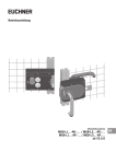
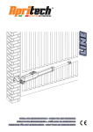
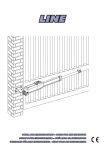
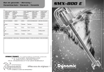
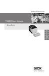
1001587-3FR-05
PSEN b3, PSEN b4, PSEN b4.1
4
4
4
D
Betriebsanleitung
GB Operating instructions
F
Manuel d'utilisation
Sicherheitsbestimmungen
Safety Regulations
Consignes de sécurité
• Installieren und nehmen Sie den Riegel nur
dann in Betrieb, wenn Sie diese Betriebsanleitung und die Betriebsanleitungen der
Sicherheitsschalter PSENcode oder
PSENmag gelesen und verstanden haben
und Sie mit den geltenden Vorschriften über
Arbeitssicherheit und Unfallverhütung
vertraut sind.
• Only install and commission the bolt if you
have read and understood these operating
instructions plus the operating instructions
for the safety switches PSENcode or
PSENmag and are familiar with the applicable regulations for health and safety at work
and accident prevention.
• Vous n’installerez et ne mettrez en service
le verrou qu’après avoir pris connaissance
et compris ce manuel d’utilisation ainsi que
les manuels d’utilisation des capteurs de
sécurité PSENcode ou PSENmag et après
vous être familiarisé avec les prescriptions
en vigueur relatives à la sécurité du travail
et à la prévention d’accidents.
Begriffsbestimmung
Terminology
Termes utilisés
PSEN b3, PSEN b4 und PSEN b4.1 werden
im Folgenden PSEN b genannt.
Auf die Unterschiede zwischen den
Geräten wird bei Bedarf hingewiesen.
PSEN b3, PSEN b4 and PSEN b4.1 are
called PSEN b in this operating instruction.
Differences between the units will be
indicated where necessary.
PSEN b3, PSEN b4 et PSEN b4.1 sont
nommés PSEN b dans la suite de ce
manuel. Les différences entre les appareils
seront signalées en cas de besoin.
Bestimmungsgemäße Verwendung
Intended use
Der Riegel PSEN b dient als mechanische
Zuhaltung nach EN ISO 12100-2 und
EN 1088. Er ist bestimmt für den Einsatz als
mechanische Verriegelung in Verbindung
mit einem Sicherheitsschalter vom Typ
• PSEN cs3.1
• PSEN cs4.1
• PSEN cs4.2
• PSEN ma1.4
PSEN b4 und PSEN b4.1 hat einen
Arretierbolzen, der das unbeabsichtigte
Schließen des Riegels z. B. durch Vibration
verhindert. Bei PSEN b4 kann der Arretierbolzen eingerastet und somit deaktiviert
werden. Bei PSEN b4.1 kann der Arretierbolzen nicht eingerastet und somit nicht
deaktiviert werden.
Der Riegel kann zusätzlich mit einem
Vorhängeschloss gegen unbefugtes Öffnen
und Schließen gesichert werden.
Eine manuell zu betätigende Fluchtentriegelung ermöglicht im Gefahrenfall ein
Aufheben der Zuhaltefunktion von der
Innenseite.
PSEN b darf nicht allein als Sicherheitsbauteil zur Vermeidung von gefährdenden
Zuständen an einer Maschine oder Anlage
eingesetzt werden.
The bolt PSEN b is used as a mechanical
guard locking device in accordance with
EN ISO 12100-2 and EN 1088. It is
designed for use as a mechanical interlock
in conjunction with a safety switch of type
• PSEN cs3.1
• PSEN cs4.1
• PSEN cs4.2
• PSEN ma1.4
PSEN b4 and PSEN b4.1 have a locking
pin, which prevents the bolt from closing
unintentionally, e.g. as a result of vibration.
On the PSEN b4, the locking pin can be
locked in position and thereby deactivated.
On the PSEN b4.1, the locking pin cannot
be locked in position and thereby cannot
be deactivated.
A padlock can also be used to protect the
bolt from unauthorised opening and closing.
A manually operated emergency release
enables the guard lock function to be
cancelled from the inside in the case of
danger.
PSEN b may not be used on its own as a
safety component to prevent hazardous
conditions on a plant or machine.
Utilisation conforme aux
prescriptions
Lieferumfang
• Türplatte mit Riegel
• Rahmenplatte mit Schließer
• Adapter zur Montage der Betätiger
• Sicherheitsschrauben (M4) zur Montage
des Adapters
• Hebel mit Kugelgriff zur
Fluchtentriegelung (nur PSEN b4 und
PSEN b4.1)
• Betriebsanleitung
Range
• Gate mounting plate with bolt
• Frame plate with latch
• Adapter for installing the actuators
• Safety screws (M4) for installing the
adapter
• Ball handle lever for emergency release
(PSEN b4 and PSEN b4.1 only)
• Operating instructions
Le verrou PSEN b sert d’interverrouillage
mécanique selon l’EN ISO 12100-2
et l’EN 1088. Il est conçu pour l’utilisation en
tant que verrouillage mécanique combiné
avec un capteur de sécurité de type
• PSEN cs3.1
• PSEN cs4.1
• PSEN cs4.2
• PSEN ma1.4
Le PSEN b4 et le PSEN b4.1 disposent
d’une targette empêchant la fermeture
involontaire du verrou causée par exemple
par des vibrations. La targette du PSEN b4
peut être verrouillée et par conséquent
désactivée. La targette du PSEN b4.1 ne
peut pas être verrouillée et par conséquent,
elle ne peut pas être désactivée.
Le verrou peut également être sécurisé par
un cadenas pour empêcher l’ouverture ou
la fermeture non autorisée grâce au trou
oblong.
Un déverrouillage de secours à actionner
manuellement permet, en cas de danger,
d’annuler la fonction d’interverrouillage du
côté intérieur.
Le PSEN b ne doit pas être utilisé seul en
tant que composant de sécurité pour éviter
les états dangereux sur une machine ou
une installation.
Contenu de la livraison
• Plaque de porte avec verrou
• Plaque pour cadre de porte avec
fermeture
• Adaptateur pour le montage d’actionneurs
• Vis de sécurité (M4) pour le montage de
l’adaptateur
• Levier avec poignée ronde pour le
déverrouillage de secours (seulement
PSEN b4 et PSEN b4.1)
• Manuel d’utilisation
Gerätebeschreibung
Unit description
Description de l’appareil
PSEN b besteht aus einer
• Türplatte mit Riegel und Griff, die an der
Schutztür befestigt wird und einer
• Rahmenplatte, die am Rahmen der
Schutztür angebracht wird.
PSEN b consists of a
• gate mounting plate with bolt and handle,
which is attached to the safety gate, and a
• frame plate, which is fitted to the safety
gate frame.
PSEN b est composé
• d’une plaque de porte avec verrou et
poignée fixée au protecteur mobile et
• d’une plaque pour cadre de porte fixée sur
le montant cadrant du protecteur mobile.
Fig. 1: Rahmenplatte, Türplatte links angeschlagen, Türplatte rechts angeschlagen/Frame plate, left-hinged gate mounting plate, right-hinged
gate mounting plate/Plaque pour cadre de porte, plaque de porte avec ouverture à gauche, plaque de porte avec ouverture à droite
Auf die Türplatte wird der Betätiger vom Typ
PSENcode oder PSENmag mit Hilfe eines
Adapters montiert, auf die Rahmenplatte der
dazu passende Sicherheitsschalter. Öffnet
der Bediener die Schutztür, wird gleichzeitig
der Sicherheitsschalter betätigt.
The PSENcode or PSENmag type actuator
is installed on to the gate mounting plate via
an adapter; the corresponding safety switch
is installed on to the frame plate. If the
operator opens the safety gate, the safety
switch is actuated at the same time.
Un actionneur de type PSENcode ou
PSENmag est monté à l’aide d’un adaptateur sur la plaque de porte. Le capteur de
sécurité correspondant est monté sur la
plaque pour cadre de porte. Lorsque
l’utilisateur ouvre le protecteur mobile, le
capteur de sécurité est actionné simultanément.
PSEN b is suitable for use on right and left
hinged gates. A padlock may also be fitted
through the slot on the bolt. This stops the
bolt from being opened or closed unintentionally or without authorisation.
PSEN b is suitable for installation on
standard aluminium profiles and machine
enclosures.
Le PSEN b est adapté à une utilisation sur
des portes avec ouverture à gauche et à
droite. Par ailleurs, il est possible de poser
un cadenas dans le trou oblong du verrou.
Cela empêche l’ouverture ou la fermeture
involontaire ou non autorisée du verrou.
Le PSEN b est adapté au montage sur des
profilés en aluminium et sur des protecteurs
de machines que l’on trouve couramment
sur le marché.
Fig. 2: Adapter/Adapter/Adaptateur
PSEN b ist für den Einsatz an links und
rechts angeschlagenen Türen geeignet. Am
Langloch des Riegels kann zusätzlich ein
Vorhängeschloss angebracht werden.
Damit wird verhindert, dass der Riegel
unbeabsichtigt oder unbefugt geöffnet oder
geschlossen wird.
PSEN b ist geeignet zur Montage an
marktüblichen Aluminiumprofilen und
Maschinenverkleidungen.
Arretierbolzen (nur PSEN b4 und
PSEN b4.1)
Locking pin (PSEN b4 and
PSEN b4.1 only)
Targette (seulement PSEN b4 et
PSEN b4.1)
Der Arretierbolzen schützt vor unbeabsichtigtem Schließen des Riegels.
The locking pin is used to protect the bolt
from closing unintentionally.
La targette protège contre une fermeture
involontaire du verrou.
ACHTUNG
Bei PSEN b4 kann der Arretierbolzen deaktiviert werden.
CAUTION
On the PSEN b4, the locking pin
can be deactivated.
ATTENTION
La targette du PSEN b4 peut être
désactivée.
WARNUNG!
Arretierbolzen darf im Gefahrenbereich nicht bedienbar sein, sonst
Gefahr von schwersten Körperverletzungen und Tod!
Schützen Sie den Arretierbolzen vor
Zugriffen z. B. durch ein ein
umlaufendes Blech (ca. 200 mm).
WARNING!
The locking pin must not be
operable in the danger zone,
otherwise there is a risk of serious
injury and death!
Protect the locking pin against
access, e.g. by means of a plate
circling it (approx. 200 mm).
AVERTISSEMENT !
Ne pas utiliser la targette dans la
zone dangereuse sinon il y a risque
de blessures corporelles graves et
mortelles !
Protégez la targette pour qu’elle
soit hors d’atteinte, par exemple,
en posant une tôle d’env. 200 mm
autour.
Bei PSEN b4 kann der Arretierbolzen in
zwei verschiedene Positionen gebracht
werden (siehe Fig. 3).
• Position 1: Der Arretierbolzen ist außer
Funktion.
• Position 2: Der Arretierbolzen arretiert
den Riegel im geöffneten Zustand, der
Riegel lässt sich nicht schließen.
On the PSEN b4, the locking pin can be
located in two different positions
(see fig. 3).
• Position 1: The locking pin is without
function.
• Position 2: The locking pin locks the bolt
in an open condition; the bolt cannot be
closed.
La targette du PSEN b4 peut être placée
dans deux positions différentes (voir fig. 3).
• Position 1 : la targette est hors service.
• Position 2 : la targette bloque le verrou en
position ouverte, le verrou ne peut pas
être fermé.
Position 1
Position 2
Fig. 3: Türplatte mit Arretierbolzen/Gate mounting plate with locking pin/Plaque de porte avec targette
Arretierung deaktivieren (Position 1)
• Arretierbolzen aus Position 2 nach oben
ziehen, gleichzeitig um 90O drehen bis
Arretierbolzen in Position 1 einrastet. Die
Arretierung ist deaktiviert.
Arretierung aktivieren (Position 2)
• Arretierbolzen aus Position 1 nach oben
ziehen, gleichzeitig um 90O drehen und
loslassen. Der Arretierbolzen muss in
Position 2 einrasten. Die Arretierung ist
aktiviert.
Deactivate locking (Position 1)
• From Position 2, pull the locking pin
upwards while turning it 90°, until the
locking pin clicks into Position 1. Locking
is deactivated.
Activate locking (Position 2)
• From Position 1, pull the locking pin
upwards while turning it 90°, then release
it. The locking pin should click into
Position 2. Locking is activated.
Désactiver le blocage (position 1)
• Tirer la targette vers le haut à partir de la
position 2, tourner simultanément sur 90O
jusqu’à ce que la targette s’enclenche en
position 1. Le blocage est désactivé.
Activer le blocage (position 2)
• Tirer la targette vers le haut à partir de la
position 1, tourner simultanément sur 90O
et relâcher. La targette doit s’enclencher
en position 2. Le blocage est activé.
Montage
Installing
Montage
ACHTUNG
Montieren Sie den Riegel nur, wenn
Sie zuvor die Betriebsanleitung der
Sicherheitschalter PSENcode oder
PSENmag gelesen und verstanden
haben! Achten Sie besonders auf
die Angaben zu Schaltabständen
und Montage. Halten Sie unbedingt
die technischen Daten ein!
CAUTION
Do not install the bolt until you have
read and understood the operating
instructions for the safety switches
PSENcode or PSENmag! Pay
particular attention to the information
on operating distances and installation. Make sure that you comply
with the technical details!
ATTENTION
Vous ne monterez le verrou qu’après
avoir préalablement pris connaissance et compris le manuel d’utilisation des capteurs de sécurité
PSENcode ou PSENmag ! Tenez
absolument compte des données sur
les distances de commutation et le
montage. Respectez impérativement
les caractéristiques techniques !
Betätiger montieren
• Montieren Sie den Betätiger auf den
Adapter.
• Montieren Sie den Adaper mit den beiden
Sicherheitsschrauben (M4) auf der
Türplatte.
Install the actuator
• Install the actuator on to the adapter.
• Using the two safety screws (M4), install
the adapter on to the gate mounting plate.
Links angeschlagene Tür/Left-hinged gate/
Protecteur avec ouverture à gauche
Montage de l’actionneur
• Montez l’actionneur sur l’adaptateur.
• Montez l’adaptateur à l’aide des deux vis
de sécurité (M4) sur la plaque de porte.
Rechts angeschlagene Tür/Right-hinged gate/
Protecteur avec ouverture à droite
Fig. 4: Betätiger montieren/Install actuator/Montage de l’actionneur
Sicherheitsschalter montieren
• Montieren Sie den Sicherheitsschalter mit
den Schrauben (M4) auf der Rahmenplatte.
Install the safety switch
• Use the screws (M4) to install the safety
switch on to the frame plate.
Montage du capteur de sécurité
• Montez le capteur de sécurité à l’aide des
vis (M4) sur la plaque pour cadre de
porte.
Fig. 5: Sicherheitsschalter montieren/Install the safety switch/Montage du capteur de sécurité
Türplatte und Rahmenplatte montieren
INFO
Montage nur bei geöffnetem Riegel
möglich!
Achten Sie bei der Montage darauf, dass
• die Montageoberfläche an Tür und
Türrahmen plan ist,
• Sie die Türplatte und die Rahmenplatte
mit der Oberkante auf gleicher Höhe
montieren.
Beachten Sie:
• Sicherheitsschalter und Betätiger nicht
als Anschlag benutzen.
• Prüfen Sie die Funktion immer mit einem
der zugelassenen Auswertegeräte.
ACHTUNG
Damit der Arretierbolzen sicher
einrastet, muss der Abstand
zwischen Türplatte und Rahmenplatte 45 mm betragen (siehe Fig.
7). Ist der Abstand größer, kann die
Tür geöffnet werden, ohne dass der
Arretierbolzen sicher einrastet.
Install the gate mounting plate and
frame plate
Montage de la plaque de porte et de la
plaque pour cadre de porte
INFORMATION
Installation can only take place when
the bolt is open!
INFORMATION
Le montage n’est possible qu’avec le
verrou ouvert !
During installation make sure that:
• The installation surface on the gate and
the gate frame is level,
• The gate mounting plate and frame plate
are aligned with the top edge.
Please note:
• Do not use the safety switch and actuator
as a limit stop.
• Always test the function with one of the
approved evaluation devices.
Lors du montage, veillez à ce que
• la surface de montage de la porte et du
cadre de porte soit plane.
• la plaque de porte et la plaque pour cadre
de porte soient alignées par rapport à la
partie supérieure.
Important :
• Ne pas utiliser les capteurs de sécurité
comme butée.
• Vérifier la fonction toujours avec l’un des
appareils de contrôle homologués.
CAUTION
To ensure that the locking pin clicks
safely into position, the gap between
the gate mounting plate and frame
plate must be 45 mm (see fig. 7). If
the gap is larger, it will be possible
to open the gate without the locking
pin clicking safely into position.
ATTENTION
Pour que la targette s’enclenche en
toute sécurité, une distance de
45 mm doit être respectée entre la
plaque de porte et la plaque pour
cadre de porte (voir fig. 7). Si la
distance est plus importante, le
protecteur mobile peut être ouvert
mais la targette ne s’enclenche pas
en toute sécurité.
Fluchtentriegelung
Emergency release
Déverrouillage de secours
Fluchtentriegelung montieren
• Entfernen Sie die Innensechskantschraube (M8).
• Montieren Sie den Hebel mit Kugelgriff mit
einem Gabelschlüssel (SW 10).
Achten Sie bei der Montage darauf, dass
der Hebel mit Kugelgriff genügend fest
angezogen ist.
Install the emergency release
• Remove the Allen screw (M8).
• Use a wrench (size 10) to install the ball
handle lever.
During installation make sure that
the ball handle lever is tightened sufficiently.
Montage du déverrouillage de secours
• Retirez la vis à six pans creux (M8).
• Montez le levier avec poignée ronde à
l’aide d’une clé plate de 10.
Pour le montage, veillez à ce que
le levier avec poignée ronde soit suffisamment serré.
Fig. 6: Türplatte mit Fluchtentriegelung, Abmessungen und Montage/Gate mounting plate with emergency release, dimensions and
installation/Plaque de porte avec déverrouillage de secours, dimensions et montage
Technische Daten/Technical Data/Caractéristiques techniques
Wirkweise/Method of operation/Actionnement
Mechanisch/mechanical/mécanique
Material/Material/Matériau du boîtier
Aluminium, Stahl verzinkt, Kunststoff/
Aluminium, galvanised steel, plastic/
Aluminium, acier galvanisé, plastique
Abmessungen siehe Abbildung/Dimensions, see graphic/Dimensions, voir l'illustration
Gewicht/Weight/Poids
PSEN b3: 984 g
PSEN b4: 1103 g
PSEN b4.1: 1105 g
Fig. 7: Montage und Abmessungen PSEN b mit PSENcode oder PSENmag am Beispiel links angeschlagene Tür/Installation and
dimensions for PSEN b with PSENcode or PSENmag, using a left-hinged gate as an example/Montage et dimensions du PSEN b
avec PSENcode ou PSENmag dans l’exemple avec protecteur ouvert à gauche
...
Technical support
+49 711 3409-444
...
Assistance technique
+49 711 3409-444
...
In vielen Ländern sind wir durch
unsere Tochtergesellschaften und
Handelspartner vertreten.
In many countries we are
represented by our subsidiaries
and sales partners.
Nos filiales et partenaires
commerciaux nous représentent
dans plusieurs pays.
Nähere Informationen entnehmen
Sie bitte unserer Homepage oder
nehmen Sie Kontakt mit unserem
Stammhaus auf.
Please refer to our Homepage
for further details or contact our
headquarters.
Pour plus de renseignements,
consultez notre site internet ou
contactez notre maison mère.
www
www.pilz.com
Pilz GmbH & Co. KG
Felix-Wankel-Straße 2
73760 Ostfildern, Germany
Telephone: +49 711 3409-0
Telefax: +49 711 3409-133
E-Mail: [email protected]
Originalbetriebsanleitung/Original instructions/Notice originale
1001587-3FR-05, 2013-06 Printed in Germany
Technischer Support
+49 711 3409-444