1
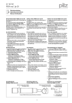
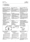
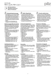
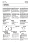
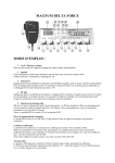
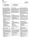
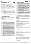
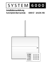
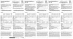
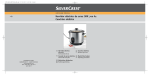
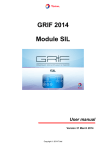
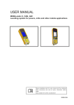
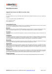
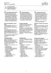
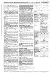
22 121-03
PSEN ma1.4a-51
4
4
4
D
Betriebsanleitung
GB Operating instructions
F
Manuel d'utilisation
22 121-03
PSEN
ma1.4a-51
Sicherheitsschalter PSEN ma1.4a-51
Safety switch PSEN ma1.4a-51
Capteur de sécurité PSEN ma1.4a-51
833339787
Der Sicherheitsschalter erfüllt Forderungen der
EN 60204-1.
Der Sicherheitsschalter erfüllt EN 60947-5-3
nur zusammen mit dem Betätiger
PSEN ma1.4-03mm oder PSEN ma1.4-10mm
und hierfür zugelassenen Auswertegeräten.
Schließen Sie den Sicherheitsschalter nur an
Auswertegeräte an, die im Abschnitt "Anschlüsse" aufgeführt sind.
The safety switch meets the requirements of
EN 60204-1.
The safety switch only complies with
EN 60947-5-3 in conjunction with the actuator
PSEN ma1.4-03mm or PSEN ma1.4-10mm
and its approved evaluation devices.
The safety switch should only be connected to
the evaluation devices listed under "Connections".
Le capteur de sécurité satisfait aux exigences
de l'EN 60204-1.
Le capteur de sécurité est conforme à la norme
EN 60947-5-3 uniquement lorsqu'il est utilisé
avec l'actionneur PSEN ma1.4-03mm ou
PSEN ma1.4-10mm et les unités de contrôle
spécialement homologuées.
Ne raccordez le capteur de sécurité qu'aux unités de contrôle indiquées dans le chapitre
« Raccordements ».
Zu ihrer Sicherheit
` Installieren und nehmen Sie das Gerät nur
For your safety
` Only install and commission the unit if you
Pour votre sécurité
` Vous n'installerez l'appareil et ne le mettrez
547263243
dann in Betrieb, wenn Sie diese Betriebsanhave read and understood these operating
en service qu'après avoir lu et compris le
leitung gelesen und verstanden haben und
instructions and are familiar with the applica- présent manuel d'utilisation et vous être faSie mit den geltenden Vorschriften über Arble regulations for health and safety at work
miliarisé avec les prescriptions en vigueur
beitssicherheit und Unfallverhütung vertraut
and accident prevention.
sur la sécurité du travail et la prévention des
sind.
Ensure VDE and local regulations are met,
accidents.
Beachten Sie die VDE- sowie die örtlichen
especially those relating to safety.
Respectez les normes locales ou VDE, parti` Any guarantee is rendered invalid if the hous- culièrement en ce qui concerne la sécurité.
Vorschriften, insbesondere hinsichtlich
ing is opened or unauthorised modifications ` L'ouverture de l'appareil ou sa modification
Schutzmaßnahmen
annule automatiquement la garantie.
` Durch Öffnen des Gehäuses oder eigenare carried out.
mächtige Umbauten erlischt jegliche Gewährleistung.
Gerätemerkmale
Unit features
` Zum Sicherheitsschalter gehört der Betätiger ` The safety switch is used with the actuator
1091646731
`
`
`
`
PSEN ma1.4-03mm oder PSEN ma1.410mm
Sicherheitsschalter mit Kabel (5 m)
2 Sicherheitskontakte (Schließer)
1 Hilfskontakt (Schließer)
Betätiger PSEN ma1.4-03mm:
– Gesicherter Schaltabstand: 3 mm
– Gesicherter Ausschaltabstand: 12 mm
Betätiger PSEN ma1.4-10mm:
– Gesicherter Schaltabstand: 10 mm
– Gesicherter Ausschaltabstand: 22 mm
eckige Bauform
Wirkweise magnetisch
Schaltspannung 24 V DC
LED zur Anzeige des Schaltzustands
1091650443
510237579
1091653387
`
`
`
`
1091670795
`
`
`
`
`
510316939
510321547
510477451
`
`
`
`
`
PSEN ma1.4-03mm or PSEN ma1.4-10mm
Safety switch with cable (5 m)
2 safety contacts (N/O)
1 auxiliary contact (N/O)
Actuator PSEN ma1.4-03mm:
– Assured operating distance: 3 mm
– Assured release distance: 12 mm
Actuator PSEN ma1.4-10mm:
– Assured operating distance: 10 mm
– Assured release distance: 22 mm
Square design
Works magnetically
Switching voltage 24 VDC
LED to display switch status
Caractéristiques de l'appareil
` L'actionneur PSEN ma1.4-03mm ou
`
`
`
`
`
763865611
`
`
`
`
-1-
PSEN ma1.4-10mm est associé au capteur
de sécurité.
Capteur de sécurité avec câble (5 m)
2 contacts de sécurité (contacts à fermeture)
1 contact d'information (contact à fermeture)
Actionneur PSEN ma1.4-03mm :
– Distance de commutation de sécurité :
3 mm
– Distance de déclenchement de
sécurité : 12 mm
Actionneur PSEN ma1.4-10mm :
– Distance de commutation de sécurité :
10 mm
– Distance de déclenchement de
sécurité : 22 mm
architecture rectangulaire
actionnement magnétique
tension commutée 24 V DC
LED pour l'affichage de l'état de commutation
Schaltabstände
Operating distances
1
2
Distances de commutation
y
3
Ein/On/Marche
Aus/Off/Arrêt
somin
Legende
` c: Seitenversatz
` d: Höhenversatz
` e: Schaltzustände (y-Achse) in Abhängigkeit
des Schaltabstands (x-Achse)
` BetätigerPSEN ma1.4-03mm
– Somin: Minimaler Schaltabstand: 0,0 mm
– Sao: Gesicherter Schaltabstand: 3 mm
– So: Typischer Schaltabstand: 3,5 mm
– Sr: Typischer Ausschaltabstand: 6 mm
– Sar: Gesicherter Ausschaltabstand:
12 mm
` Betätiger PSEN ma1.4-10mm
– Somin: Minimaler Schaltabstand: 0,0 mm
– Sao: Gesicherter Schaltabstand: 10 mm
– So: Typischer Schaltabstand: 12,5 mm
– Sr: Typischer Ausschaltabstand: 16 mm
– Sar: Gesicherter Ausschaltabstand:
22 mm
1091685643
Seiten- und Höhenversatz
` Betätiger PSEN ma1.4-03mm
1100369803
sao so
sr
sar
(mm) x
Légende
Key
` c: Lateral offset
` c: Décalage latéral
` d: Vertical offset
` d: Décalage en hauteur
` e: Switch statuses (y-axis) dependent on the ` e: Etats de commutation (axe y) en fonction
operating distance (x-axis)
de la distance de commutation (axe x)
` ActuatorPSEN ma1.4-03mm
` Actionneur PSEN ma1.4-03mm
– Somin: Minimum operating distance:
0,0 mm
– Sao: Assured operating distance: 3 mm
– So: Typical operating distance: 3,5 mm
– Sr: Typical release distance: 6 mm
– Sar: Assured release distance: 12 mm
` Actuator PSEN ma1.4-10mm
– Somin: Minimum operating distance:
0,0 mm
– Sao: Assured operating distance: 10 mm
– So: Typical operating distance: 12,5 mm
– Sr: Typical release distance: 16 mm
– Sar: Assured release distance: 22 mm
– Somin : Distance de commutation
minimale : 0,0 mm
– sao : Distance de commutation de
sécurité : 3 mm
– So : Distance de commutation approximative : 3,5 mm
– Sr : Distance approximative de déclenchement : 6 mm
– Sar : Distance de déclenchement de sécurité : 12 mm
` Actionneur PSEN ma1.4-10mm
– Somin : Distance de commutation
minimale : 0,0 mm
– sao : Distance de commutation de
sécurité : 10 mm
– So : Distance de commutation approximative : 12,5 mm
– Sr : Distance approximative de déclenchement : 16 mm
– Sar : Distance de déclenchement de sécurité : 22 mm
Lateral and vertical offset
` Actuator PSEN ma1.4-03mm
Décalage latéral et en hauteur
` Actionneur PSEN ma1.4-03mm
Gesicherter Ausschaltabstand Sar: Max. 12 mm Assured release distance Sar: Max. 12 mm with Distance de déclenchement de sécurité Sar :
bei alle Höhen- und Seitenversätzen
all vertical and lateral offsets
12 mm max. pour tous les décalages latéraux
et en hauteur
Gesicherter Schaltabstand Sao in mm/Assured operating distance Sao in mm/Distance de commutation de sécurité Sao en mm
Seitenversatz/Lateral offset/ Décalage latéral
Höhenversatz/
Height offset/
Décalage en
hauteur
0
1
2
3
0
3,0
3,0
2,5
1,5
1,0
1
3,0
2,5
2,0
0,5
-
2
2,5
1,5
1,0
-
-
3
1,5
0,5
-
-
-
4
0,5
-
-
-
-
Die angegebenen Werte sind gültig bei einer
Temperatur von 20 °C.
` Betätiger PSEN ma1.4-10mm
Gesicherter Ausschaltabstand Sar: Max. 22 mm
bei alle Höhen- und Seitenversätzen
1100376715
1100371211
The stated values are valid at a temperature of
20 °C.
` Actuator PSEN ma1.4-10mm
Assured release distance Sar: Max. 22 mm with
all vertical and lateral offsets
4
Les valeurs indiquées sont valables pour une
température de 20 °C.
` Actionneur PSEN ma1.4-10mm
Distance de déclenchement de sécurité Sar :
22 mm max. pour tous les décalages latéraux
et en hauteur
Gesicherter Schaltabstand Sao in mm/Assured operating distance Sao in mm/Distance de commutation de sécurité Sao en mm
Seitenversatz/Lateral offset/ Décalage latéral
Höhenversatz/
Height offset/
Décalage en
hauteur
0
2
4
6
8
0
10,0
10,0
9,0
7,0
5,0
2
10,0
10,0
8,0
6,0
3,0
4
9,0
8,0
7,0
5,0
-
6
7,0
6,0
5,0
-
-
Die angegebenen Werte sind gültig bei einer
Temperatur von 20 °C.
1100376715
The stated values are valid at a temperature of Les valeurs indiquées sont valables pour une
20 °C.
température de 20 °C.
-2-
Verdrahtung
Wiring
Câblage
Beachten Sie:
Please note:
Important :
` Angaben im Abschnitt „Technische Daten“ ` Information given in the “Technical details” ` Tenez compte impérativement des données
unbedingt einhalten.
must be followed.
indiquées au chapitre "Caractéristiques
` Berechnung der max. Leitungslänge Imax im ` Calculation of the max. cable runs lmax in the techniques".
` Calcul de la longueur de câble max. Imax sur
Eingangskreis:
input circuit:
le circuit d'entrée :
Rlmax
Rlmax
Imax =
Imax =
Rlmax
Rl / km
Rl / km
Imax =
Rl / km
Rlmax = max. Gesamtleitungswiderstand
Rlmax = max. overall cable resistance (see
Rlmax = résistance max. de l'ensemble du
(s. techn. Daten)
Technical details)
câblage (voir les caractéristiques techniRl / km = Leitungswiderstand/km
Rl / km = cable resistance/km
ques)
` Beachten Sie bei Einsatz von Auswertegerä- ` When using evaluation devices with delay-on
Rl /km = résistance du câblage/km
ten mit rückfallverzögerten Kontakten:
de-energisation contacts, please note:
– Verzögerungszeit ≤30 s: die rückfallverzö– Delay time ≤30 s: Delay-on de-energisation ` En cas de mise en œuvre d'appareils de congerten Kontakte genügen den Anforderuncontacts satisfy the requirements of catetrôle avec contacts temporisés à la retomgen der Kategorie 3 gemäß EN 954-1 bzw.
gory 3 in accordance with EN 954-1 and
bée, il faut tenir compte des indications
den Anforderungen an PDF mit Einfehlersithe requirements of a PDF with single-fault
suivantes :
cherheit (PDF-S).
tolerance (PDF-S).
– Temporisation ≤30 s : les contacts tempo– Verzögerungszeit ≥ 30 s: die rückfallverzö- – Delay time ≥ 30 s: Delay-on de-energisarisés à la retombée satisfont aux prescripgerten Kontakte genügen den Anforderuntion contacts satisfy the requirements of
tions de la catégorie 3 selon l'EN 954-1, et/
gen der Kategorie 1 gemäß EN 954-1 bzw.
Category 1 in accordance with EN 954-1
ou aux prescriptions des PDF avec sécuriden Anforderungen an PDF mit Zuverläsand the requirements of a PDF with deté de défaut unique (PDF-S).
sigkeit durch besonderes Design (PDF-D).
signed reliability (PDF-D).
– Temporisation ≥ 30 s : les contacts tempo` Überprüfen Sie in folgenden Fällen von Inbe- ` In the following commissioning cases, check
risés à la retombée satisfont aux prescriptriebnahme die Funktion Querschlusserkenthe function that detects shorts across contions de la catégorie 1 selon l'EN 954-1, et/
nung:
tacts:
ou aux prescriptions des PDF avec une
– Bei Auswertegeräten mit Versorgungs– On evaluation devices with DC supply
fiabilité obtenue grâce à un design particuspannung DC: Gesamtleitungswiderstand
voltage: Overall cable resistance
lier (PDF-D).
≥ 15 Ohm pro Kanal
≥ 15 Ohms per channel
` Vérifiez dans les cas suivants de mise en ser– Bei Auswertegeräten mit Versorgungs– On evaluation devices with AC supply volt- vice la fonction de détection des courtsspannung AC: Gesamtleitungswiderstand
age: Overall cable resistance ≥ 25 Ohms
circuits :
≥ 25 Ohm pro Kanal
per channel
– pour les appareils de contrôle avec ali– Wie Sie die Querschlussprüfung durchfüh- – For details of how to perform the test for
mentation DC : Résistance de l'ensemble
ren müssen, entnehmen Sie der entspreshorts across the contacts, please refer to
du câblage ≥ 15 ohms par canal
chenden Bedienungsanleitung des
the operating manual for the relevant eval- – pour les appareils de contrôle avec aliAuswertegeräts.
uation device.
mentation AC : Résistance de l'ensemble
du câblage ≥ 25 ohms par canal
– vous trouverez dans la notice d'utilisation
de l'appareil de contrôle comment exécuter le contrôle des courts-circuits.
492354955
Anschlüsse
Connections
Raccordements
Anschlussbelegung
Terminal assignment
Der Sicherheitsschalter ist in unbetätigtem Zu- The safety switch is shown in an unoperated
stand dargestellt.
condition.
807841803
Belegung des 8-adrigen Kabels/Layout of the 8-core
cable/Repérage du câble à 8 conducteurs
6
3
1
4
2+
7
5
8
807945483
WICHTIG
Der Hilfskontakt mit LED
` darf mit PNOZ X-Geräten nur mit Versorgungsspannung bis 24 V DC betrieben
werden
` ist mit PNOZ X-, PNOZelog- und
PNOZmulti-Geräten nicht in Reihe
schaltbar
rosa/pink/rose
grün/green/vert
weiß/white/blanc
gelb/yellow/ambre
braun/brown/marron
blau/blue/bleu
grau/grey/gris
rot/red/rouge
NOTICE
The auxiliary contact with LED
` May only be operated with a supply voltage up to 24 VDC on PNOZ X units
` May not be connected in series with
PNOZ X, PNOZelog and PNOZmulti
units
-3-
Repérage des broches
Le capteur de sécurité est représenté en position de repos.
NC
NC
IMPORTANT
Le contact d'information avec LED
` ne doit être utilisé, pour les appareils
PNOZ X, qu'avec une alimentation jusqu'à 24 V DC
` ne peut pas être monté en série avec les
appareils PNOZ X, PNOZelog et
PNOZmulti
Anschluss an Auswertegeräte
` Anschluss an Meldeausgang mit LED
Connection to evaluation devices
` Connection to signal output with LED
PNOZ X, PNOZsigma, PNOZelog
A1/+24V
Raccordement aux unités de contrôle
` Raccordement à la sortie d'information avec
LED
PNOZmulti, PSS, PSSu
1
braun/brown/brun
A1/+24V braun/brown/brun
2
3
4
4
5
5
I7
7
blau/blue/bleu
8
` Anschluss an PNOZ X, PNOZsigma,
7
` Raccordement aux PNOZ X, PNOZsigma,
PNOZelog
PNOZelog
S11
PNOZ e1p
PNOZ e1.1p
PNOZ e1vp
PNOZ e6.1p
PNOZ e6vp
PNOZ s3
PNOZ s4
PNOZ s5
6
8
` Connection to PNOZ X, PNOZsigma,
PNOZelog
2
3
6
GND blau/blue/bleu
1
PNOZ X2C
PNOZ X2
PNOZ X2.7P
PNOZ X2.8P
PNOZ X2.9P
S21
S12
S22
weiß/white/blanc
grün/green/vert
gelb/yellow/ambre
rosa/pink/rose
1
2
3
4
5
6
7
8
A1
A1
S32
PNOZ e5.11p
S42
weiß/white/blanc
grün/green/vert
gelb/yellow/ambre
rosa/pink/rose
1
2
3
4
5
6
7
8
S31
PNOZ X3.1
PNOZ X3P
PNOZ X3
PNOZ X3.10P
PNOZ XV2
PNOZ XV2P
PNOZ XV3
PNOZ XV3P
S21
S32
S22
weiß/white/blanc
grün/green/vert
gelb/yellow/ambre
rosa/pink/rose
1
2
3
4
5
6
7
8
` Anschluss an PNOZmulti
` Connection to PNOZmulti
` Raccordement au PNOZmulti
T1
T0
Schutztür/safety gate/protecteur mobile
Schaltertyp 3/switchtype 3/type du capteure 3
I0, I1: Eingänge/inputs/entrées
T0, T1: Taktausgänge/test pulse outputs/sorties
impulsionelles
I1
I0
weiß/white/blanc
grün/green/vert
gelb/yellow/ambre
rosa/pink/rose
1
2
3
4
5
6
7
8
-4-
` Anschluss an PSS mit oder ohne
SafetyBUS p und PSSu
` Connection to PSS with or without
` Raccordement au PSS avec ou sans
SafetyBUS p and PSSu
SafetyBUS p et PSSu
O17
O16
Schutztür/safety gate/protecteur mobile
Schaltertyp 3/switchtype 3/type du capteure 3
I0, I1: Eingänge/inputs/entrées
O16, O17: Taktausgänge/test pulse outputs/sorties
impulsionelles
I1
I0
weiß/white/blanc
grün/green/vert
gelb/yellow/ambre
rosa/pink/rose
1
2
3
4
5
6
7
8
928691211
ACHTUNG!
Die Sicherheitsschalter dürfen an einer PSS
nur mit dem Standardfunktionsbaustein
SB064 oder SB066 betrieben werden.
CAUTION!
The safety switches may only be operated
on a PSS in conjunction with standard
function block SB064 or SB066.
ATTENTION !
Les capteurs de sécurité ne doivent être
utilisés sur un PSS qu'avec le bloc de fonction standard SB064 ou SB066.
Montage
Installation
Installation
` Berücksichtigen Sie bei der Montage die An- ` When installing make sure you comply with ` Veuillez tenir compte lors du montage des
1095033099
forderungen der DIN EN 1088
the requirements of DIN EN 1088
exigences de la normes DIN EN 1088.
` Montieren Sie Sicherheitsschalter und Betä- ` The safety switch and actuator should be in- ` Montez le capteur de sécurité et l'actionneur
tiger parallel gegenüberliegend.
ACHTUNG!
Eine Umgebung mit elektrisch oder magnetisch leitfähigem Material kann die Geräteeigenschaften beeinflussen. Prüfen Sie die
Schaltabstände und den gesicherten Abschaltabstand.
` Befestigen Sie Sicherheitsschalter und Betätiger ausschließlich mit Schrauben M4 mit
flacher Kopfunterseite aus nicht magnetischen Material (z.B. M4-Zylinderkopf- oder Flachkopfschrauben).
INFO
Sichern Sie den Betätiger gegen unbefugtes Entfernen und vor Verschmutzung. Verschließen Sie die Montageöffnungen mit
den mitgelieferten Verschlüssen.
INFO
Verschlüsse (1), (2), (3) entsprechen den UL
94 V0-Anforderungen, Verschluss (4) entspricht nicht den UL-Anforderungen.
` Anzugsdrehmoment max. 0,8 Nm.
` Beachten Sie unbedingt den Abstand zwischen zwei Sicherheitsschaltern (siehe Technische Daten).
` der gesicherte Schaltabstand Sao und der
gesicherte Ausschaltabstand Sar müssen unter realen Bedingungen überprüft werden.
Sicherheitsschalter und Betätiger
` von Eisenspänen fernhalten
` keinen starken Magnetfeldern aussetzen
` keinen starken Stößen oder Schwingungen
aussetzen
` nicht als Anschlag benutzen
` nur für feste Verkabelung
stalled opposite each other in parallel.
CAUTION!
The unit's properties may be affected if installed in an environment containing electrically or magnetically conductive material.
Please check the operating distances and
the assured release distance.
` Safety switches and actuators should only
be secured using M4 flat head screws made
of non-magnetic material (e.g. M4 cheesehead or pan head screws).
INFORMATION
The actuator should be protected from unauthorised removal and from contamination. Close the mounting holes using the
seals provided.
INFORMATION
Seals (1), (2), (3) meet the requirements of
UL 94 V0; seal (4) does not meet UL requirements.
` Torque setting max. 0.8 Nm.
` The distance between two safety switches
must be maintained (see Technical details).
` The assured operating distance Sao and the
assured release distance Sar must be tested
under real conditions.
Safety switches and actuators
` Should be kept away from iron swarf
` Should not be exposed to strong magnetic
fields
` Should not be exposed to heavy shock or vibration
` Should not be used as a limit stop
` For fixed wiring only
-5-
l'un en face de l'autre de manière parallèle.
ATTENTION !
Un environnement avec des matériaux
conducteurs de l'électricité ou du magnétisme peut affecter les caractéristiques de
l'appareil. Veuillez vérifier les distances de
commutation et la distance de déclenchement de sécurité.
` Pour fixer le capteur de sécurité et l'actionneur, utilisez uniquement des vis M4 dans
des matériaux non magnétiques et dont la
tête présente une face inférieure plate
(exemple : vis M4 cylindriques ou à tête plate).
INFORMATION
Assurez-vous que l'actionneur ne puisse
être ni retiré sans autorisation, ni encrassé.
Refermez les ouvertures du montage à
l'aide des fermetures fournies.
INFORMATION
Les fermetures (1), (2), (3) satisfont aux exigences de l'UL 94 VO ; la fermeture (4) ne
satisfait aux exigences UL.
` Couple de serrage max. 0,8 Nm.
` Veuillez absolument respecter la distance
entre les capteurs de sécurité (voir les caractéristiques techniques).
` La distance de commutation de sécurité Sao
et la distance de déclenchement de sécurité
Sar doivent être vérifiées dans de réelles
conditions.
Le capteur de sécurité et l'actionneur
` doivent être éloignés des copeaux métalliques
` ne doivent pas être exposés à des champs
magnétiques élevés
` ne doivent pas subir des chocs et vibrations
importants
` ne doivent pas être utilisés comme butée
` ne doivent être utilisés que dans un câblage
fixe
Montage Variante 1
` 1. Gewinde (M4) in gewünschter Position
schneiden.
` 2. Sensor mit einer Schraube fixieren.
` 3. Zweite Schraube in Sensor eindrehen.
(Wichtig: Schrauben nicht fest anziehen).
Schrauben für Betätiger eindrehen, dabei
den Abstand Schraubenkopf zur Auflage beachten: ca. 3 ... 6 mm.
` 4. Betätiger zu Sensor ausrichten.
INFO
Die beschriftete Fläche des Betätigers (aktive Fläche) muss zum Sensor zeigen.
` 5. Betätiger auf die Schrauben schieben.
` 6. Sensor ausrichten und die Schrauben mit
max. 0,8 Nm anziehen.
` 7. Betätiger ausrichten und die Schrauben
mit max. 0,8 Nm anziehen.
` 8. Verwendete Montageöffnungen mit Verschluss (1) oder (4) schließen.
` 9. Nicht verwendete Montageöffnungen mit
Verschluss (2) schließen.
` 10. Montageöffnungen auf aktiver Fläche mit
Verschluss (3) schließen.
` 11. Sensor und Betätiger sind fertig montiert.
1086268427
Installation type 1
` 1. Cut the thread (M4) in the required position.
` 2. Use a screw to fix the sensor.
` 3. Attach the second screw to the sensor.
`
`
`
`
`
`
`
`
(Important: do not tighten the screws). Attach
the screws for the actuator, maintaining the
distance between the screw head and the
plate: ca. 3 ... 6 mm
4. Align actuator to sensor.
INFORMATION
The inscribed area on the actuator (active
surface) must point to the sensor.
5. Slide the actuator on to the screws.
6. Align the sensor and tighten the screws to
a max. 0.8 Nm.
7. Align the actuator and tighten the screws
to a max. 0.8 Nm.
8. Close used mounting holes using seal (1)
or (4).
9. Close unused mounting holes using seal
(2).
10. Close mounting holes on the sensing
face using seal (3).
11. Installation of sensor and actuator is now
complete.
-6-
Montage du modèle 1
` 1. Couper le filetage (M4) dans la position
souhaitée.
` 2. Fixer le capteur à l'aide d'une vis.
` 3. Visser la deuxième vis dans le capteur.
(Important : ne pas serrer les vis à fond). Visser les vis pour l'actionneur, pour cela, respecter la distance entre la tête de vis et
l'application : env. 3 à 6 mm
` 4. Orienter l'actionneur par rapport au capteur.
INFORMATION
La surface de l'actionneur avec une inscription (surface active) doit être orientée vers
le capteur.
` 5. Pousser l'actionneur sur les vis.
` 6. Orienter le capteur et serrer les vis avec
max. 0,8 Nm.
` 7. Orienter l'actionneur et serrer les vis avec
max. 0,8 Nm.
` 8. Refermer les ouvertures destinées au
montage à l'aide des fermetures (1) ou (4).
` 9. Refermer les ouvertures non utilisées pour
le montage à l'aide de la fermeture (2).
` 10. Refermer les ouvertures destinées au
montage, situées sur la surface active, à
l'aide de la fermeture (3).
` 11. Le capteur et l'actionneur sont à présent
montés.
Montage Variante 2
Montieren Sie den Sensor wie bei Montage Variante 1
` 1. Schrauben für Betätiger eindrehen, dabei
den Abstand Schraubenkopf zur Auflage beachten: ca. 3 ... 6 mm.
` 2. Nicht verwendete Montageöffnungen, die
auf der Auflagefläche aufliegen, mit Verschluss (2) schließen.
` 3. Betätiger auf die Schrauben schieben.
` 4. Betätiger ausrichten und die Schrauben
mit max. 0,8 Nm anziehen.
` 5. Verwendete Montageöffnungen mit Verschluss (1) oder (4) schließen.
` 6. Montageöffnungen auf aktiver Fläche mit
Verschluss (3) schließen.
` 7. Sensor und Betätiger sind fertig montiert.
1086273035
Installation type 2
Install the sensor as shown for installation type
1
` 1. Attach the screws for the actuator, maintaining the distance between the screw head
and the plate: ca. 3 ... 6 mm.
` 2. Close unused mounting holes on the plate
using seal (2).
` 3. Slide the actuator on to the screws.
` 4. Align the actuator and tighten the screws
to a max. 0.8 Nm.
` 5. Close used mounting holes using seal (1)
or (4).
` 6. Close mounting holes on the sensing face
using seal (3).
` 7. Installation of sensor and actuator is now
complete.
-7-
Montage du modèle 2
Montez le capteur de la même manière que
pour le modèle 1
` 1. Visser les vis pour l'actionneur, pour cela,
respecter la distance entre la tête de vis et
l'application : env. 3 à 6 mm.
` 2. Refermer à l'aide de la fermeture (2) les
ouvertures non utilisées pour le montage qui
se trouvent dans la surface d'application.
` 3. Pousser l'actionneur sur les vis.
` 4. Orienter l'actionneur et serrer les vis avec
max. 0,8 Nm.
` 5. Refermer les ouvertures destinées au
montage à l'aide des fermetures (1) ou (4).
` 6. Refermer les ouvertures destinées au
montage, situées sur la surface active, à
l'aide de la fermeture (3).
` 7. Le capteur et l'actionneur sont à présent
montés.
Justage
Adjustment
Ajustement
1095251595
` Prüfen Sie die Funktion immer mit einem der ` Always test the function with one of the ap- ` Vérifiez la fonction uniquement avec l'un des
zugelassenen Auswertegeräte.
proved evaluation devices.
` Bei unbetätigten Reedkontakten leuchtet die ` The LED lights when the reed contacts are
appareils de contrôle homologués.
` La LED s'allume lorsque les contacts Reed
LED (Schutzeinrichtung geöffnet oder Siunoperated (safety device open or safety
ne sont pas actionnés (dispositif de proteccherheitsschalter und Betätiger falsch juswitch and actuator wrongly adjusted). The
tion ouvert ou capteur de sécurité et actionstiert). Die LED befindet sich im Öffnerkreis
LED is in the safety switch's N/C circuit. The
neur mal ajustés). La LED se trouve dans le
LED goes out when the reed contacts are op- circuit d'ouverture du capteur de sécurité.
des Sicherheitsschalters. Bei betätigten
erated.
Lorsque les contacts Reed sont activés, la
Reedkontakten erlischt die LED.
` Die angegebenen Schaltabstände (siehe
` The stated operating distances (see Techni- LED s'éteint.
technische Daten) gelten nur, wenn Sichercal details) only apply when the safety switch ` Les distances de commutation mentionnées
dans les caractéristiques techniques sont
heitsschalter und Betätiger parallel gegenand actuator are installed facing each other
valables uniquement lorsque le capteur de
überliegend montiert sind. Andere
in parallel. Operating distances may deviate
sécurité et l'actionneur sont montés l'un en
Anordnungen können zu abweichenden
if other arrangements are used.
` Note the maximum permitted lateral and ver- face de l'autre de manière parallèle. D'autres
Schaltabständen führen.
` Beachten Sie den maximal zulässigen Seitical offset (see "Operating distances" and
montages peuvent conduire à des distances
ten- und Höhenversatz (siehe "Schaltabstän- "Max. lateral and vertical offset").
de commutation divergentes.
` Respectez le décalage latéral et en hauteur
de" und "Max. Seiten- und Höhenversatz").
maximal autorisé (voir « Distances de
commutation » et « Décalage latéral et en
hauteur maximum »).
Abmessungen in mm
Dimensions in mm
Actuator
26,4
37
4,5
22
37
8
R8
14,4
22
n
Technische Daten
14,4
19
4,5
Safety switch
18
Dimensions en mm
18
Technical details
18
Caractéristiques techniques
Elektrische Daten
Schaltspannung
Innenwiderstand
Max. Schaltstrom Sicherheitskontakte
Max. Schaltstrom Hilfskontakte
Electrical data
Switching voltage
Internal resistance
Max. switching current for safety
contacts
Max. switching current for auxiliary
contacts
Max. Schaltleistung SicherheitsMax. breaking capacity for safety
kontakte
contacts
Max. Schaltfrequenz
Max. switch frequency
Umweltdaten
Environmental data
Umgebungstemperatur
Ambient temperature
Schwingungen nach EN 60947-5-2 Vibration to EN 60947-5-2
Frequenz
Frequency
Amplitude
Amplitude
EMV
EMC
Schockbeanspruchung
Shock stress
Verschmutzungsgrad
Pollution degree
Bemessungsisolationsspannung
Rated insulation voltage
Bemessungsstoßspannungsfestig- Rated impulse withstand voltage
keit
-8-
Données électriques
Tension de commutation
Résistance interne
Courant max. de commutation des
contacts de sécurité
Courant max. de commutation contacts d'information
Puissance max. de commutation
des contacts de sécurité
Fréquence de commutation max.
Données sur l'environnement
Température d'utilisation
Vibrations selon EN 60947-5-2
Fréquence
Amplitude
CEM
Résistance aux chocs
Niveau d'encrassement
Tension assignée d'isolement
Tension assignée de tenue aux
chocs
24 V
10 Ohm
0,20 A
10 mA
5,0 W
1 Hz
-10 - 55 °C
10 - 55 Hz
0,35 mm
EN 60947-5-3
30g , 11 ms
3
250 V
4,0 kV
Mechanische Daten
Betätiger
Mechanical data
Actuator
Données mécaniques
Actionneur
Hysterese typ.
Betätiger PSEN ma1.4-03mm
Betätiger PSEN ma1.4-10mm
Schaltabstände
Gesicherter Schaltabstand Sao
PSEN ma1.4-03mm
Min. Schaltabstand Somin
PSEN ma1.4-03mm
Gesicherter Ausschaltabstand Sar
PSEN ma1.4-03mm
Gesicherter Schaltabstand Sao
PSEN ma1.4-10mm
Min. Schaltabstand Somin
PSEN ma1.4-10mm
Gesicherter Ausschaltabstand Sar
PSEN ma1.4-10mm
Min. Abstand zwischen Sicherheitsschaltern
Betätiger PSEN ma1.4-03mm
Betätiger PSEN ma1.4-10mm
Anschlussart
Kabel
Leitung
Schutzart Gehäuse
Gehäusematerial
Abmessungen siehe Abbildung
Gewicht
Sicherheitsschalter
Betätiger PSEN ma1.4-03mm
Betätiger PSEN ma1.4-10mm
Sicherheitstechnische
Kenndaten
B10d nach EN ISO 13849-1 und
EN IEC 62061
Lambdad/Lambda nach
EN IEC 62061
Hysteresis typ.
Actuator PSEN ma1.4-03mm
Actuator PSEN ma1.4-10mm
Switching distances
Assured operating distance Sao
PSEN ma1.4-03mm
Min. operating distance Somin
PSEN ma1.4-03mm
Assured release distance Sar
PSEN ma1.4-03mm
Assured operating distance Sao
PSEN ma1.4-10mm
Min. operating distance Somin
PSEN ma1.4-10mm
Assured release distance Sar
PSEN ma1.4-10mm
Min. distance between safety
switches
Actuator PSEN ma1.4-03mm
Actuator PSEN ma1.4-10mm
Connection type
Cable
Cable
Protection type, housing
Housing material
Dimensions, see graphic
Weight
Safety switch
Actuator PSEN ma1.4-03mm
Actuator PSEN ma1.4-10mm
Safety-related characteristic
data
B10d in accordance with
EN ISO 13849-1 and EN IEC 62061
Lambdad/Lambda in accordance
with EN IEC 62061
Hystérésis env.
Actionneur PSEN ma1.4-03mm
Actionneur PSEN ma1.4-10mm
Distances de commutation
Portée de travail assurée Sao
PSEN ma1.4-03mm
Portée de travail min. Somin
PSEN ma1.4-03mm
Portée de déclenchement assurée Sar
PSEN ma1.4-03mm
Portée de travail assurée Sao
PSEN ma1.4-10mm
Portée de travail min. Somin
PSEN ma1.4-10mm
Portée de déclenchement assurée Sar
PSEN ma1.4-10mm
Distance minimale entre les capteurs de sécurité
Actionneur PSEN ma1.4-03mm
Actionneur PSEN ma1.4-10mm
Type de connection
Câble
Câble
Indice de protection du boîtier
Matériau du boîtier
Dimensions, voir l'illustration
Poids
Capteur de sécurité
Actionneur PSEN ma1.4-03mm
Actionneur PSEN ma1.4-10mm
Caractéristiques techniques de
sécurité
B10d selon EN ISO 13849-1 et
EN IEC 62061
Lambdad/Lambda selon
EN IEC 62061
PSEN ma1.4-03mm
PSEN ma1.4-10mm
2,5 mm
3,5 mm
3 mm
0,0 mm
12 mm
10 mm
0,0 mm
22 mm
50 mm
50 mm
5m
LiYY 8 x 0,14 mm²
IP6K9K
PBT
220 g
16 g
18 g
7.300.000
0,75
Es gelten die 2009-04 aktuellen Ausgaben der The standards current on 2009-04 apply.
Les versions actuelles 2009-04 des normes
Normen.
s'appliquent.
INFO
INFORMATION
INFORMATION
Bestellnummern und Zubehör finden Sie im
Order numbers and accessories can be
Vous trouverez les références et les accesTechnischen Katalog oder auf unserer Infound in the Technical Catalogue or on our
soires dans le catalogue technique ou sur
ternetseite www.pilz.com.
Internet site www.pilz.com.
notre site www.pilz.com.
1128680331
EG-Konformitätserklärung
EC Declaration of Conformity
Déclaration de conformité CE
Diese(s) Produkt(e) erfüllen die Anforderungen
der Richtlinie 2006/42/EG über Maschinen des
europäischen Parlaments und des Rates. Die
vollständige EG-Konformitätserklärung finden
Sie im Internet unter www.pilz.com.
Bevollmächtigter: Norbert Fröhlich,
Pilz GmbH & Co. KG, Felix-Wankel-Str. 2,
73760 Ostfildern, Deutschland
This (these) product(s) comply with the requirements of Directive 2006/42/EC of the European
Parliament and of the Council on machinery.
The complete EC Declaration of Conformity is
available on the Internet at www.pilz.com.
Authorised representative: Norbert Fröhlich,
Pilz GmbH & Co. KG, Felix-Wankel-Str. 2,
73760 Ostfildern, Germany
Ce(s) produit(s) satisfait (satisfont) aux exigences de la directive 2006/42/CE relative aux machines du Parlement Européen et du Conseil.
Vous trouverez la déclaration de conformité CE
complète sur notre site internet www.pilz.com.
Représentant : Norbert Fröhlich,
Pilz GmbH & Co. KG, Felix-Wankel-Str. 2,
73760 Ostfildern, Allemagne
1139424011
-9-
Originalbetriebsanleitung/Original instructions/Notice originale
22 121-03, 2009-12 Printed in Germany Printed in Germany
22 121-03
Printed
2009-12
in Germany