1
USE AND MAINTENANCE MANUAL
Pag. 4
H
2.2
GB
ELECTRICAL CONNECTION
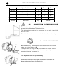
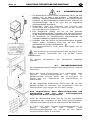
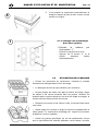
1. Connection to the power supply must be made with a main
switch (H) it must be omnipolar and interrupt all contacts
including neutral. There must be a distance of at least 3
mm between open contacts, and it must have a thermal
magnetic safety switch or fuses which are able to
withstand the maximum power indicated on the plate.
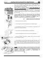
2. Make sure that the power supply corresponds to that on
the technical features plate on the right side of the
machine.
3. Use an effective earthing system in compliance with local laws to
protect the safety of the operators and not damage the machine.
4.
Do not use adapters, multiple sockets or extension cords.
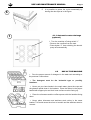
5. The equipment must be included in an equipotential
system, and connected using a screw marked with the
symbol.
The equipotential wire must be 10 mm² .
If the power supply cable (provided with the equipment) needs to
be replaced use another H07RN-F type with the same dimensions.
For additional information see the wiring drawing.
2.3
WATER CONNECTION
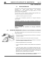
Set-up the site according the attached plumbing drawing.
E
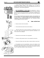
Before connecting the equipment make sure that a gate valve
has been placed between the water supply and the
equipment so that the water can be turned off if required or
for repair work.
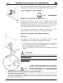
Use a hose to connect the solenoid valve (E) to the gate
valve (V) and make sure that the delivery is not less than
20l/min.
Check that the temperature and water pressure correspond to
what is shown on the technical specifications plate.
V
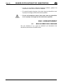
If the water is harder than what is listed in the chart, it is
advisable to install a decalcifier upline from the solenoid
valve.
If there are high concentrations of very conductive minerals
in the water, it is advisable to install a demineralization
system calibrated to the hardness shown in the following
chart.