1
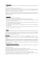
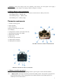
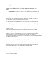
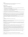
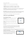
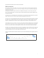
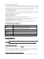
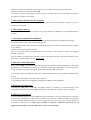
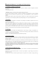
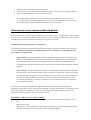
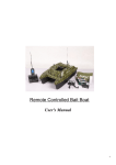
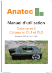
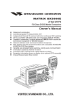
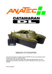
Remote Controlled Bait Boat
(For monohull S and 3B)
User's Manual
Contents
▀ STRUCTURE & FUNCTION INSTRUCTION
▀ TECHNICAL SPECIFICATION
▀ INSTALLATION GUIDE
▀ SAFTY NOTES
▀ REMOTE CONTROLLER
▀ 3 HOPPERS VERSION
▀ FISH FINDER OPERATION
We appreciate for your trust and great support!
Please read this manual carefully. It may offer you the necessary information to operate the boat
properly.
▀ STRUCTURE & FUNCTION INSTRUCTION (For one-tank bait boat)
1. Main Battery : A lead accumulator 6Volts / 10A is located
inside the hull, providing roughly 60 minutes of continuesly
operating.
2. Tuning Rail: by moving the battery along the rail you can
equilibrate the load in the boat.
3. Motor: A ventilated electric motor powers the boat.
4. Electronic Board: It contains the fuse carrier, the radio
receiver and the speed controller. The electronic board can be
completely removed from the boat. It is held by 2 screws and a
clip at the back (lift it up once the 2 screws are removed). All
elements can be unplugged to remove the board.
5. Radio Receiver: Receive the radio signal from the remote
control and distribute the commands to all the boat's
component.
6. Rudder Mechanism: Control the direction of the boat.
7. Speed Controller: Drive the motor to forward or backward.
8. Fuse: 10 Amps. They protect the speed controller in case
the motor is stuck by something. Use only 10 Amps fuses.
9. Greaser tube on the propeller axis
Greaser: Allows lubricating the propeller axis with the can of
pressurised grease.
10. Rudder Servomotor: Adjusting the direction of the
rudder by servomotor.
11. Bait Tank:
Allows carrying the baits to the precise spot where you want to fish. Maximum load is 1kg. It is mounted on a rail so that it can be easily
removed for cleaning or transport. A lock forbids it to be removed freely.
12. Clip to lock the bait tank: Locking the bait tank.
13. Screwing point for the antenna: Screw the antenna.
14. Bait Tank Servomotor: Allows opening and closing the bait tank.
15. Rear Light: Two red LEDs at the back help to visualise the bait boat when it is moving away.
16. Light Switch: Switch the light on and off.
17. Main ON/OFF Switch: Power up the boat.
18. Cover: When removed allows to access the batteries and the electronic board.
19. Front Light: Made by two ultra bright white LEDs. It helps to visualise the boat when it is coming back to the shore.
▀ TECHNICAL SPECIFICATION
Product Name
Product Type
Battery Power
Remote Controlled Bait Boat
Monohull
Battery of Boat: 6V/10A (A lead accumulator)
Battery Usage Time
Remote Distance
Battery of remote control handset: 8 “AA” Alkaline Battery
2-3 hours (Continuously Usage)
300-400 米
2
Sailling Speed
Wave Resistance
Charger Voltage
Bait Tank
Bait Tank Loading
1-3 M/S (Adjustable)
About 5-6 Class
AC 110-240V
1PCS or 3PCS
1KG/PCS (Maximum)
▀ INSTALLATION GUIDE
Before any utilisation,
* We advise you keeping the shipping box of the boat in case you may return it for repairing.
* You must charge up your accumulators to full at first!
STEP 1: [Setting up the battery]
(1) Setting up the battery in the boat
Check the main switch [17] is OFF before connecting or disconnecting the battery.
Lift up the cover. Place the battery in its housing [2], located in the hull, near the front. Then, close the
cover.
Note: The battery is given for approximately 70 charge cycles. Beyond this it will not provide
necessary power for proper operating time. It will be time to renew it then. We suggest you to buy a
back up battery to meet emergent condition.
(2) Setting up the batteries in the remote control handset
Over turn the remote control handset and open the cover. Then, put in the 8 “AA” Alkaline Batteries and
pay attention the battery’s polarity. For proper use of the remote control, you should totally unfold the
antenna.
Then, power up the remote control handset with the [ON] switch.
A level meter on the front side shows the batteries charge for the remote control handset. Be aware of
that if this level is too low to operate the boat properly.
STEP 2. [Setting up the receiver antenna]
To ensure a good radio signal reception, the receiver antenna should always be in place. It is screwed at
the rear of the boat.
STEP 3. [Setting up the bait tank]
The bait hopper can be removed easier. Make sure it is locked [12] after you placed it on its rail.
Once you place the three hoppers in the boat, make sure you have locked all of them in the corresponding
position.
STEP 4. [Check the switch]
(1) The external switch [16] controls the light of the boat.
(2) [17] is the main ON/OFF switch of the boat. When it is in OFF, all electric components inside the
boat are disconnected from the power supply. You should manipulate any electric device on the boat to
make sure the main switch is OFF.
Before powering up the boat with the main switch [17] in the ON position, please check follow items:
a- The remote control is powered on and its battery level is high enough.
b- The battery is well in place inside the boat and plugged properly.
c- The antennas of the boat and the remote control are both in place and completely unfolded.
3
STEP 5. [Power up of the boat]
Once the previous steps have been observed you can activate the boat, switch ON the boat.
Note: Before you put the boat into water,
You are advised to check that all the boat components are operating properly before you start navigates.
* When the boat is powered-on, the speed controller will take a few second to load its operating program.
During this time you have no control on the motor. After that, if the motor is still not running, check the
fuse located inside the boat, on the electronic board, is not burned or out of place.
* Control the remote controller in the largest power position to check the battery level. The battery charge
monitor LED is installed in the rear of the boat. It indicates the level of the battery.
LED blinking Green ----Battery Full ;
LED blinking Orange ----Battery Weak ;
LED blinking Red----Battery Empty;
If it indicates the green light, you could put the boat into the water, otherwise, you need charge the
battery to full.
STEP 6. [Add the fishing bait & hooking the fishing line]
Place the fishing line in the bait tank by passing the line under the tank; and then close it by the
potentiometer on the remote control handset. Hook the wire using the cutting out opening foreseen for
that purpose.
Please Note:
a- Do not exceed 1 kg fishing bait in each tank to avoid destruction of the servomotor by overheating.
b- Never run the boat backward when the fishing line is hooked on to avoid the wire will be not
caught by the propeller.
c- Not press the board of bait hopper heavily by hand. It will damage the bait tank servomotor.
d- Power up the remote control handset AND the boat main switch before setting the fishing line or
any bait in the hopper. Otherwise radio-electric hazard may trigger un-voluntarily the opening of
the hopper mechanism.
STEP 7. [Start navigating]
The boat could start navigating if everything is ready then.
▀ SAFETY NOTES
1. [Transport & Storage]
(1)
You should never transport the boat with the battery inside. Transport the battery separately and
protect it from shocks.
★ Warning: The battery is filled with liquid acid, which is a very toxic product. In case shocks occur
during transport, some acid may escape and generate important damage. In case of contact
between the acid liquid and your skin or yours eyes you should rinse abundantly with fresh
water and consult a doctor.
(2) You should always store the boat in a dry and ventilated place. Never leave the boat enclosed in its
transporting bag for a long period of time, unless it is completely dried out.
4
2. [Waterproof]
(1) The electronic devices inside the boat are protected against humidity. Avoid exposing them directly to
the water.
(2) Avoid the water penetrate inside the boat's hull.
If water comes in contact with the electric motor it may create a short circuit and damage some electric
components. Never put the boat into water without the cover in place. Grease the propeller axis on a
regular basis to avoid that water penetrates inside the hull.
Since we can not ensure that all the parts of the boat are totally water proof, make sure that before you
sail the boat, all the water that may be inside has been removed from the hull to prevent electric short cut
in the electronic devices.
3. [Lubricate]
Make sure to lubrify before first utilisation!
* Remove the cover and get the edge of the transparent tube, under the electronic board.
* Connect the red part (tube) to the pressurised grease can. Inject the grease inside the tube. Use only the
pressurised can supplied with the boat.
* You should repeat this operation on a regular basis for optimum boat performance and to prevent water
to come inside the boat along the propeller axis.
* For a good penetration of the grease into the transmission you can run slowly the motor while you
inject the grease.
* To be efficient, the lubrify process should be done before you put the boat into water. Injecting the
grease when the propeller axis is wet is useless.
4. [Fuse]
The fuse is located on the electronic board, inside the boat, and is protected by a black cap. The fuse only
protects the speed controller against overload. Overload can occur if for some reason the propeller
rotation is blocked while the motor is running. The speed controller will then eat up and burn. The fuse is
here to burn in place of the speed controller.
Please Note:
a- Never replace the fuse by a short cut or by a fuse with a value higher than 10 Amps. Should the
propeller be stuck the fuse will not burn but the speed controller will instead and be then totally
destroyed.
b- The fuse does not protect the other electronic devices inside the boat against inversion of polarity
at the battery level. It may catch fire and cause serious damage of the boat. Under the principle that the
battery connectors cannot be plugged in the wrong way, you should be very careful once you change or
connect the battery.
5. [Charge and storage the battery]
(1) Connect the charger's output to the battery to be charged. The connector has a mechanism that
prevents
to plug it the wrong way.
(2) Connect the charger's main plug to the electric network (220 Volts -50 Hz).
(3) Since the 6V/10Ah battery is not totally charge after leaving factory, you need charge it for about 15
hours at the first time; and charge about 8-10 hours later for every time.
(4) Disconnect the charger's main plug from the 220 Volts before you disconnect the battery.
(5) If you don't use the boat for a period of time, do not leave the battery empty. Charge it as soon as
possible after usage and then for maintenance charge it 1 hour every month.
5
★ WARNING: Protect the charger from rain, humidity, heat sources, fire and sparks. Never plug a
defective battery to the charger. Never plug a defective charger to a battery.
6. LED for Battery charge monitoring
The LED (voltspy) is located at the rear of the boat. It monitor the 6V battery of the boat
LED blinking green → Battery full
LED blinking orange → Battery weak
LED blinking red → Battery empty
▀ REMOTE CONTROLLER
1- Antenna screwing point
2- Move forward
3- Move backward
4 Resting point tuning for the motor
5 LCD display
6- Configuration switches (DO NOT TOUCH)
7- Resting point tuning for the rudder
8- Rudder left command
9- Main switch
10- Rudder right command
11- Bait hopper command
12- Battery power indicator
X412 RC controler for Mono S GR and SE GR
CH03 RC controller for Mono S N and SE N
1. [Remote controller operation]
Slide the main switch (9) to the [ON] position to power up the remote controller handset.
(1)
Right joystick: Moving it horizontaly controls the rudder position. The position is proportional
(2)
to the joystick position. In the resting position the rudder should be in the middle position. If
needed you can use the trimmer 7
6
(3) Left joystick: Moving it vertically controls the motor forward (push) and backward (pull) direction.
The power of the motor is proportional to the joystick position.
Moving it horizontally controls the front line dropper on each side (on DL3 only). Moving to the
right drops the right side line and moving to the left drops the left side line. When released it
returns automatically to its resting position.
2. [Riding the boat]
---Push the left joystick to go forward.
---Pull it to go backward.
---Move the right joystick to control the boat's direction
It is strongly recommended that you always allow the joysticks to return to their middle position for a
second before you change the direction of a motor.
The joystick is proportional, meaning that the speed of the motor depends on the stick position. Avoid
sudden change of speed or direction on the motors to spare battery life. To spare more battery life
avoid to run the motors at full speed, just keep them a little below full speed.
Also think that when the boat is far, with wind and waves, and fully loaded with boilies, it takes a few
seconds when you send a command and the boat actually react.
3. [Bait hopper potentiometer]
Turning the potentiometer right opens proportionally the bait hopper flap, turning it left close it back.
If you use big baits do not close totally the flaps back as bait may be stuck and smashed by the flaps
and this may create unnecessary constraints in the mechanism. Instead close the flap just enough to
block the boillies. It is advised that for efficient use of the bait hopper you make some testing and
calibrate your potentiometer. Never push the flaps by hand while the boat is powered on. Instead use
the remote control.
4. [Quartz]
Define the channel number for communication between the RC handset and the boat. Both the RC
handset and the radio receiver inside the boat must have the same channel number to operate. Should
you change channel, pull on the quartz to change it and do the same on the boat's radio receiver.
▀ 3 HOPPERS VERSION
.Setting up the side hoppers
The 2 hoppers are identical and symetrical so any one can be mounted on any sde
−
place the hopper so that the mounting plate holes fit into the 2 long screws located on each side of
−
the boat.
−
Then screw the 4 butterfly bolts .
7
−
Pass the é cables through the hole in the hull and the guide below the hopper
−
2 settings are possible to command the opening of the 2 hoppers either simultaneously or
separately.
Separate opening of the hoppers
−
Simultaneous opening of the hoppers
To change the configuration you must :
1. remove the small screw at the center of the servomotor cross and remove the cross
2. Change the position on one of the cable hook on the cross. To do this gently open the cable hook with
a small screw driver
3. Turn power on for the boat and the radio controllers
4. put back the cross on the servomotor axe, vertically for simultaneous opening, and with an angle of
45° for separate opening
5. do not forgot to put back the small screw but not too tight.
−
Never transport the boat with the 2 side hoppers mounted, they may be broken easilly
−
If you choose separate opening for the side hopper, mind about the weight that is on each hopper so
that the boat keeps a good balance in every circonstance.
▀ FISH FINDER OPERATION
You may have a fish finder pre-installed in your boat. This
include
• a probe installed below the hull,
• an electronic device connected to the probe and to the antenna,
• a switch at the rear of the boat to turn it on and off
1- Connector (at the back)
2- Depth indication reading
3- Water surface line
4- Air temperature reading
5- Fish Icon
6- Bottom line drawing
7- Depth Range indication
8- Sensibility indication
9- Battery level indication
10- Power up/Down key
11- ENT key
12- MENU and EXIT key
13/14- Navigating keys
15- Antenna receptacle
8
Power supply for the transmitter box :
The transmitter box may be powered from any battery source between 5.2 Volt and 12 Volt. Be careful
not to plug it wrong: the black only wire is the negative and the black and white wire is the
positive.
−
For the ALF20 : We strongly advice that you use a 9.6 Volt alcaline battery. Even if the 6 Volt
battery of the boat may seems convenient, the ALF20 does not have sufficient power supply filtering.
Thus the electro magnetic noise generated when the boat is running will be injected in the transmitter box
which will then show abnormal operation.
For theALF30 : You can use the boat's 6 Volt battery as the power supply for the transmitter
−
box. Thus you can monitor the battery level of the boat and show it on the screen. Then you know exactly
how much power is left on your boat. You can also use other powering sources like a 9;6 Volt or a 12
Volt battery but you loose the monitoring function of the boat's battery.
Note: The radio range is somewhat dependant of the power supply voltage of the transmitter box. The
more voltage, the more distance on the radio. You may choose the power source according to the specificity of your fishing spot and the distance you need for the radio compare to the comfort of having the
boat's battery monitored.
Once the internal transmitter in the boat has been turned on by the switch on the boat's deck you can turn
on the receiver screen.
To do so press briefly on the power up key (10). To shut down press the key for 3 seconds. When
shuttled down if you press the power key and hold it for 3 second you will enter the DEMO mode.
When the receiver is receiving good radio signal from the transmitter the small line materialising the water surface (3) is moving to the left. If the screen shows a picture the whole picture will shift to the left. If
the radio signal get lost or confused, the picture shift will stop and resume when radio is back.
If the boat is not in the water, the information given by the fish finder are not relevant and should not be taken to
state if the device works good or not.
Important note: the range of the high frequency radio may be strongly influenced by atmospheric conditions such as air humidity. When the air is dry the radio range may exceed 300 meters. The more the air is
humid, the less the range will be. Under rain the range may be shortened to 150 or even 100 meters.
Make sure of the power level of the 9 volt battery of the fish finder in the boat for a good radio range.
When operating, the screen shows a plot of successive depth measurement that it recorded. The plot is
moving from the right to the left, the latest measurement is shown on the right side.
[Operating instruction of the menu]
Power on key
* Press briefly to power up the receiver.
* Press for 3 seconds to shut down.
* Press for 3 second to enter demo.
9
ENT key
* In normal operating mode press this key to freeze the display. Press again to resume.
* In menu mode this key is used to confirm a setting (enter).
MENU / EXIT key
* Press this key to enter the MENU mode.
* Press it again to leave the MENU mode.
* When the device is in the MENU mode, the sensitivity, battery level and depth range indications that
are in the bottom of the screen disappear.
* Use the arrows keys to navigate through the chapters of the MENU.
* Use the ENT key to enter in the selected chapter. When doing so the frame of the chapter appear in bold.
* Use again the arrows to set the value of the parameter.
* Press the ENT key to confirm the new setting. The frame bold disappear.
* Press EXIT to return to normal operation. The status indication at the bottom of the screen then returns.
SENSITIVITY This parameter defines how the echo will be shown on the screen. The highest the sensitivity the more details will be shown. In situations where the screen shows many glitches and small echo
returns, reducing the sensibility will help filter the glitches. If sensitivity is too low, most of the small
echo returns will be ignored which may influence the fish identification mode. When water is clear or in
deep water try to rise the sensibility to see even the smallest returns.
When water is dirty or agitated try to lower the sensibility to show only the useful parts of the echo returns.
CHANNEL This should always be set to Channel 1 (CH1)
SHALLOW This is used to generate an alarm when the depth is less than the value of the parameter. To
disable this function the parameter should be set to 0.
DEPTH RANGE This parameter defines the maximum depth value corresponding to the bottom of the
screen. If set to AUTO the bottom line will shows abrupt break in the bottom line plot, corresponding to
the automatic change of scale.
FISH ID This parameter defines how the detected targets are shown on the screen. If ON a fish icon will
be displayed when a submarine object is detected. If OFF an arch will be displayed instead.
The device cannot make the difference between a fish or any other type of objects that may be floating in
the water (plastic bag, air bubbles, etc...) It is then possible shows you a fish while there is none.
The fish ID function is still very useful to help you interpret the information on the screen. The processor
filters the weakest echo returns to concentrate on showing the stronger echo that have more chances to
correspond to a real fish..
Thus if you want to see a maximum of information on what is happening under the boat we recommend
to disable the fish ID and analyse the small echo returns. But if you are more interested at detecting
fishes, turn the function on.
UNITS This parameter defines in which units length and temperature are displayed.
BACKLIGHT This is for the lightening of the screen which may be permanent (on) or automatic in
1
0
function of external conditions.
CONTRAST Tune it at your convenience to obtain the best readability.
LOAD DFT: Select this mode to reload all parameter with their default value.
Additional Functions on ALF30, not available on ALF20
MONITOR SEL: This function allows to select which information is shown at the top left corner of the
screen, just below the depth reading. The available monitoring sources are : Air temperature, Water
temperature and battery level on the transmitter box power supply.
BAT ALARM: set an alarm on the battery level of the transmitter box. When the battery level is lower
than the value specified here the alarm is triggered. The screen will then show a VTGLOW message and
a sound alarm will be issued. To desactivate the alarm specify a value of 0 in this parameter.
LANGUAGE: Select your prefered language : English, French, German, Russian.
[Advice for a good utilisation]
How the fishfinder is working.
The probe emits periodically a vibration similar to a sound wave but
with a frequency
such that you cannot hear it. This is called an ultrasonic wave.
This wave propagate inn water at a speed much higher that it would be
on the air
and with much less attenuation on the signal strength. So when the
probe is not in
the water, the measurement it shows are not relevant. Good result are shown only
when in water.
The emitted wave is then reflected on the bottom and part of it returns to the probe.
This is called the echo. The echo is detected by the electronic which uses the time
taken for the wave to reflect on the bottom and travel back to the probe to calculate
the length of the travel and deduce the depth of water.
The probe generate a wave which is emitted in a cone of 80°spreading under the boat. If an object is
present then it will reflect the wave and generate an echo that the probe will receive before
the main echo from the bottom.
When the boat is close to the shore, it may happen that the
depth reading do not show accurate information. This is due to
the angle of emission of the probe. It is then possible that a
strong echo is received from the reflection of the wave on the
shore before the reflection on the real bottom.
1
1
The measurement will then not be accurate for the bottom.
[Radio transmission]
The metallic transmitter box feature a micro processor which analyse the returned signals and transmit
the information by radio to the receiver screen, also featuring a micro processor which then display the
information on the screen.
The frequency used for this radio connection is 433MHz. This frequency is also used by many other
device such as mobile phones, car remote control, wireless byte alarm, planes, military equipment, and
also other fish finders.
If an other device is transmitting on the same frequency it will confuse the original signal from your fish
finder. Then the receiver screen may stop moving, indicating that the radio is lost.
In some cases it is also possible that the radio of the boat's remote controller makes interferences with the
fish finder. This is possible because when a radio signal is emitted it also contains multiple of the base
frequency, called harmonics which may then correspond to the sensibility of the fish finder receiver.
If this happens you may try to take your receiver screen apart from the RC handset and see if the problem
goes away. If it is the case we can try to change the quartz value on your RC handset and on your boat's
receiver to try to shift a little bit on the frequency so that it will no more interfere with the fish finder.
The radio wave emitting by the antenna on the boat is propagating in almost all direction but a larger part
is reflecting by the water surface and is kind of sliding on the water surface. Thus you will get a better
result if you hold your receiver with an angle of 45°with the water.
If there is an obstacle between the boat and the screen, this will considerably reduce the quality of the reception.
1
2
Contact Information And After Sales Service:
Please pay attention to the following point before you return a boat or a fish finder to the after sale
service.
− Keep the original packaging so that you could use it to return the boat
−
−
−
−
−
−
We remind you that the sending cost are at your charge.
Before sending a boat contact your local after sale to check if the problem can not be solved
without returning the boat. The reason is that sending a boat for transport is always dangerous as
it may be broken during bad manipulation.
All boats components are quite easy to identify and change. In most case is it faster and cheaper
to give a call to your local service that can then send you the appropriate spare part
Should you send a boat anyway : never send the batteries with the boat, first they are heavy
which raise the price of transport, second they represent a risk of damage to the boat during
transport and third they are not covered by the warranty (unless it is first time use). Pack the boat
carefully in its original packaging to minimise risk of damage
Return the boat using a transport company, not by postal service as they usually do not provide
insurance if the boat is damaged during transport. We can not be responsible for damage during
transport.
If the problem is with the Graupner remote controller, you can send directly your controller to
Graupner after sales service. Contact us to know where is your local Graupner service.
The first place you should turn for warranty is where you get the boat from. If you do not know where to
ask, please send an email to [email protected] to locate the nearest after sale service.
ANATEC cannot make sure that everyone observe correctly the operating instructions nor the maintenance
of the boat or the remote control. Thus we decline any responsibility for loses, damages and cost that
may result of a miss usage or disfunctioning.
Location :
ANATEC France:
14 Rue de la Perdrix
93420 Villepinte
Fax +33 (0)1 41 53 93 57
Postal Address
ANATEC
BP 89051
95933 Roissy Charles De Gaulle CEDEX
1
3
ANATEC
Manuel d’utilisation de
L‘AMORCEUR MONOCOQUE.
Vous venez d’acquérir un produit Anatec et nous vous remercions de la confiance que vous
nous avez accordée.
Lisez cette notice attentivement, elle vous apportera les informations nécessaires à la bonne
utilisation de votre bateau.
Avant toute utilisation, effectuez la mise en chargement de la
batterie.
▀ VUE GENERALE
1. Batterie principale : Un accumulateur
principal au plomb 6 Volts / 10 Ah, est placé
dans la coque, donnant une autonomie de 60
minutes environ.
2. Rail de positionnement : Emplacement
permettant d’équilibrer au mieux le bateau
suivant la charge, en déplaçant la batterie dans le
rail.
3. Moteur : Un moteur ventilé assure la
propulsion du bateau.
4. Plaquette électronique : à l’intérieur du
bateau, tenu par 2 vis, elle est constituée du porte
fusible, du récepteur et du variateur de vitesse.
Cette plaquette a été
pensée de manière à
pouvoir être extraite complètement du bateau,
tous les éléments sont déconnectables par prise
in-inversable.
5. Récepteur radio : Reçoit le signal radio
envoyé par l’émetteur, et transmet les
informations à tous les éléments de
l’Amorceur.
6. Mécanisme de gouvernail.
7. Variateur de vitesse : un variateur contrôle la
vitesse du bateau.
8. Fusibles : d’une valeur de 10 Ampères, ils protègent le variateur de vitesse contre tout blocage du
moteur. Utiliser strictement des fusibles 10 ampères.
1
4
9. Tube graisseur de l’arbre d’hélice
Permet de lubrifier l’arbre d’hélice. Graisser régulièrement l'arbre d'hélice avec la bombe de graisse
fournie. Utiliser exclusivement la graisse fournie avec le bateau. Pour que la graisse pénètre correctement
dans la transmission faire tourner le moteur doucement pendant le graissage. Procéder au graissage
exclusivement avant de mettre le bateau dans l'eau. Graisser avant ou après ne sert à rien.
10. Servomoteur de gouvernail:
11. Bac d’amorçage arrière: Permet de transporter les amorces jusqu’au point de pêche, charge
maximale 1kg. Réalisé sur glissière, il peut être facilement démonté pour le transport et le nettoyage, un
système de blocage en position interdit de l’extraire.
12. Clips de blocage de bac.
13. Point de vissage de l’antenne.
14. Servomoteur de bac : permet d’ouvrir ou de fermer le bac d’amorçage.
15. Éclairage arrière : Deux diodes rouges permettent de mieux repérer l’Amorceur lorsqu’il s’éloigne.
16. Interrupteur d’éclairage : Permet de connecter ou de couper l’éclairage du bateau
17. Interrupteur ON/Off : Mise sous tension du bateau.
18. Couvercle : Permet la mise en place de la batterie et d’accéder à la plaquette électronique.
19. Éclairage avant : Constitué de 2 diodes blanches.
▀ SPECIFICATION TECHNIQUE
Produit
Amorceur monocoque radio commandé
Batteries
Batterie du bateau : 6V/10A (accumulateur au plomb)
Autonomie
Distance de controle
Vitesse sur l'eau
Resistance aux
vagues
Chargeur
Bac à amorce
Charge maxi
Batterie de la radio commande: 8 piles alkalines “AA”
1 heure 30 mn (utilisation en continu)
400 m
1,3 m/s (Ajustable)
Classe 5-6
AC 110-240V
1 bac ou 3 bacs
1 kg par bac
▀ MISE EN SERVICE
Avant toute utilisation
(1) Conservez le carton d'emballage du bateau, pour le cas ou vous devez renvoyer le bateau
en réparation.
(2) effectuez la mise en charge des batteries du bateau ainsi que de la télécommande
1. Mise en place de la batterie
Vérifier que l’interrupteur général on/off [17] est coupé (OFF) avant de connecter ou déconnecter la
batterie.
Soulever le couvercle, Placer la batterie dans son logement [ 2 ] situé dans la coque vers l’avant . La
batterie est donnée pour une utilisation d’environ 70 charges, au-delà elle n’aura plus l’énergie
nécessaire pour une autonomie correcte, il sera donc utile de la renouveler.
2. Mise en place des Piles dans la télécommande.
Retourner la télécommande et ouvrir le couvercle. Utiliser des piles de type LR6 au nombre de 8,
1
5
respecter strictement les polarités, refermer puis sortir en entier l’antenne pour toute utilisation.
Mettre sous tension en activant le bouton ON.
Un curseur en façade, vous indique le niveau des piles, surveiller celui-ci, un niveau trop bas ne permet
pas d’utiliser le bateau correctement.
3. Mise en place de l’antenne de réception.
Pour assurer une bonne réception du signal radio, l’antenne doit être branchée. L’antenne se visse à
l’arrière de l’Amorceur.
4. Mise en place du bac.
Le bac est amovible, veillez à le sécuriser avec les clips de blocage [12] après l’avoir positionné dans la
glissière.
5. Graissage avant première utilisation
Soulever le couvercle et faites sortir le tube translucide passant par-dessus la plaquette électronique.
Connecter la partie rouge (tube) à la bombe de graisse.
Graisser régulièrement l’arbre d’hélice en injectant de la graisse à l’aide de la bombe de graisse fournie
avec le bateau.
Utiliser exclusivement la graisse fournie.
Pour que la graisse pénètre correctement dans la transmission, faire tourner le moteur à bas régime
pendant le graissage.
Pour être efficace, le graissage doit toujours se faire avant la partie de pêche, (avant que le bateau soit mis
dans l’eau), graisser pendant ou après ne sert a rien.
6. Mise sous tension du bateau.
Sur la position OFF, l’ensemble des éléments électriques est coupé du système d’alimentation. Pour toute
manipulation sur les éléments électriques de l’Amorceur, vérifier que l’interrupteur est en position fermé.
Avant de mettre en marche l’interrupteur général [17] défini par ON vérifier que :
a- L’émetteur radio-commandé est sous tension (télécommande) et le niveau de piles de télécommande
est bon.
b- La batterie est branchée correctement dans le bateau.
c- Les antennes sont en place et dépliées complètement. (Bateau & télécommande)
7. Éclairage de l’Amorceur.
L’interrupteur [16] placé à l’extérieur du bateau permet de connecter le circuit d’éclairage. Pour
Connecter, manœuvrer l’interrupteur [16] matérialisé par un soleil pour mettre en service l’éclairage.
8. Mise à l'eau du bateau
Il est recommandé de faire un test préalable de bon fonctionnement, sur tous les éléments de l ‘Amorceur
avant de le faire naviguer. Lors de la mise en marche de l’Amorceur le variateur recherche le programme
de fonctionnement, attendre pendant 5 secondes, durant ce temps vous n’avez pas le contrôle des gaz. Si
le moteur ne fonctionne pas, vérifier que le fusible se trouvant à l’intérieur du bateau, sur la
plaquette électronique, ne soit pas détérioré ou sorti de son logement.
1
6
▀ MODE D'EMPLOI ET CONSEILS D'UTILISATION
1. Transport et stockage de l’Amorceur.
Il ne faut jamais transporter l’Amorceur avec la batterie à l’intérieur. Veiller à transporter la batterie
séparément,
en la protégeant des chocs.
Attention! La batterie contient de l’acide, produit extrêmement toxique.
En cas de chocs pendant le transport, l’acide peut s’échapper des accumulateurs et causer des dégâts
importants. En cas de contact avec la peau ou les yeux, rincer abondamment à l’eau et consulter un
médecin.
Prendre garde à toujours stocker l’Amorceur dans un endroit sec et ventilé. Ne jamais laisser l’Amorceur
enfermé dans son sac de transport, pendant une période prolongée, s’il n’est pas complètement sec.
2. Étanchéité.
Les appareillages électroniques de l’Amorceur sont protégés de l’humidité. Cependant éviter de les
exposer directement à l’eau.
Éviter qu’une quantité importante d’eau ne pénètre dans le fond de la coque. Si le moteur électrique
trempe dans l’eau, il risquerait de se court-circuiter. Ne jamais faire naviguer l’Amorceur sans son
couvercle. Graisser régulièrement l’arbre d’hélice pour éviter que l’eau ne remonte dans la coque. Ne
pouvant garantir une étanchéité totale, veiller à ce qu’il n’y ai plus d’eau dans l’Amorceur durant le
transport, ceci afin d’éviter tout court-circuit dans les systèmes électroniques.
3. Graissage
Le graissage de l'arbre d'hélice doit impérativement se faire lorsque le bateau est totalement sec.
Cependant il n'est pas utile de trop graisser. Lorsque de l'eau remonte par l'arbre d'hélice à l'intérieur de
la coque c'est que le graissage est insufisant.
Reportez vous au chapitre précédent pour la procédure de graissage.
4. Fonction du fusible.
Positionné sur la plaquette électronique à l’intérieur du bateau, recouvert par un capuchon noir, le fusible
protège uniquement le variateur de vitesse contre tout corps étranger pouvant venir bloquer l’hélice
pendant la rotation.
Ne jamais réparer le fusible par un pontage ou le remplacer par un fusible supérieur à 10 Ampères. Si un
fusible supérieur à 10 A est installé dans le bateau, en cas de blocage de l’hélice celui-ci ne remplira pas
sa fonction de coupure, le variateur serait détruit définitivement.
Le fusible ne protègent en aucun cas d’autres éléments de l ‘Amorceur, ni contre tout inversement
de polarité. Toute inversion de polarité endommagerait tous les circuits électriques avec un risque
important d’incendie.
5. Mise en place de la ligne dans le bac .
Placer la ligne dans le bac en passant par dessous, puis refermer en actionnant le potentiomètre de la
télécommande.
Positionner le fil dans l’échancrure faite a cet effet. Ne pas dépasser 1 kg de charge, afin d’éviter la
destruction du servo.
Ne jamais faire reculer l’Amorceur quand la ligne est en position sur le bateau, la ligne pourrait se
1
7
prendre dans l’hélice.
Rappel, mettre la radio-commande sous tension avant la mise en Place de la ligne ainsi que le bateau.
Dans le cas contraire des parasites peuvent déclencher intempestivement le largage de la ligne et des
amorces.
6. Mode d’emploi chargement batterie .
- Connecter le cordon de sortie du chargeur à la jonction in inversable de la batterie à charger.
- Connecter le boîtier enfichable du chargeur à une prise de courant 220 Volts -50 Hz.
- Laisser la batterie 6V/10Ah en charge pendant 15 heures, ni plus, ni moins.
- Déconnecter le boîtier de la prise de courant 220 Volts.
- Déconnecter du chargeur la batterie.
Conseils importants.
Protéger le chargeur de la pluie et de l’humidité. Protéger le chargeur des sources de chaleurs, flammes
ou étincelles.
Ne jamais brancher une batterie défectueuse ou endommagée au chargeur. Ne jamais brancher un
chargeur défectueux ou endommagé.
7. stockage et charge des batteries .
Lors de la réception de ou des batteries, celles-ci ne sont pas chargées complètement. Chargez les
10 heures avant utilisation du bateau sur l’eau.
Eviter de laisser les batteries déchargées pendant une longue période. Rechargez les dés que possible, si
vous les stockez longtemps sans utilisation, procéder à une charge de maintien de 1 heure tous les mois.
10. LED témoin de charge des batteries
Celle ci est installée à l'arrière du bateau.
LED verte clignotante → Batterie pleine
LED Orange clignotante → Batterie faible
LED Rouge clignotante → Batterie vide
.
▀ TELECOMMANDE
1- Antenne à visser
2- Marche Avant
3- Marche Arrière
4 Réglage du point de repos pour le
moteur
5 Ecran LCD
6- Interrupteur de configuration (NE
PAS TOUCHER)
7- réglage du point de repos du
gouvernail
8- commande gauche du gouvernail
9- Interrupteur marche/arrêt
télécommande CH03 pour mono S N et SE N
1
8
10- commande droite du gouverail
11- Commande d'ouverture du volet de
trappe.
12- Témoin d charge des batteries
télécommande X412 pour mono S GR et SE GR
1. [Utilisation de la télécommande]
(1) Glisser l’interrupteur principal (9) vers la position ON pour mettre la radio commande sous
tension.
(2) Joystick Droit: Le déplacement horizontal contrôle la position du gouvernail. Celle ci est
proportionnelle à la position du joystick.
Au repos, le joystick étant au millieu, le gouvernail est sur sa position millieu. Vous pouvez ajuster
cette position en jouant sur le trimmer 7.
(3) Joystick Gauche: Le déplacement vertical contrôle le moteur en marche avant (pousser) et en
marche arrière (tirer). La puissance du moteur est proportionnelle à la position du joystick.
La position de repos du moteur est lorsque le joystick est au millieu. Vous pouvez régler cette position
par le trimmer 4
2. [Conduite du bateau]
---Pousser la manette gauche pour faire avancer le bateau.
---Tirer la manette gauche pour faire reculer le bateau.
---Déplacez la manette droite vers la droite ou la gauche pour contrôler la direction du bateau
ATTENTION, il est impératif de toujours laisser revenir la manette de commande du moteur au point
neutre (une seconde), avant tout changement de rotation des moteurs.
. La commande est proportionnelle, c'est-à-dire que la vitesse de rotation du moteur dépend de la
position de la manette. Éviter les changements brutaux du régime du moteur. Pour prolonger la
durée de vie de l'accumulateur, maniez la manette de vitesse avec douceur, évitez de les enfoncer ou
de les lâcher brutalement.
Pour augmenter encore l’autonomie de l’Amorceur, évitez de faire tourner le moteur à fond.
Préférez une allure plus modérée qui économise l’énergie des accumulateurs.
3. [Potentiomètres d’ouverture de trappe.]
Le potentiomètre contrôle l'ouverture et la fermeture proportionnelle du volet de trappe.
Plus on tourne le potentiomètre dans le sens des aiguilles d’une montre, plus la trappe est ouverte,
jusqu’à la position d’ouverture maximale. En ramenant le potentiomètre dans le sens inverse, la trappe
1
9
se referme.
Attention ! Une fois que la trappe est entrouverte, il ne faut pas tenter de la refermer fond mais juste
ce qu'il faut pour arrêter vos bouillettes sans les écraser et forcer sur le mécanisme. Dans le cas
contraire, des amorces coincées entre les volets peuvent empêcher la trappe de se refermer et forcer
sur le mécanisme d’ouverture.
Il est vivement conseiller de faire de essais préalable et de repérer la position de la trappe sur le
potentiomètre.
Ne pas dépasser 1 kg de poids dans la trappe. Ne jamais appuyer sur le volet de trappe pour les
manœuvrer à la main quand le bateau est sous tension
4. [Quartz]
Il définit le numéro de canal pour la communication entre la télécommande et le bateau. Le quartz de la
télécommande et celui se situant sur le récepteur radio à l'intérieur du bateau doivent avoir la même
valeur. Si vous devez changer les quartz parce que quelqu'un d'autre a le même numéro et que cela crée
des interférences, tirez dessus pour l'enlever et faite de même avec celui du récepteur radio.
VERSION 3 BACS
Mise en place des bacs
les 2 bacs sont identiques et réversible, c'est à dire qu'il n'y a pas de sens de montage
−
placer le bac pour que les pattes de fixation se positionnent sur les 2 vis longues situées de
−
chaque cotés de la coque.
Serrez les pattes sur la coque avec les 4 papillons fournis.
−
Passer le cable de retenu à travers le trou dans la coque et le guide en bas du bac
−
Deux montages sont possible pour soit commander l'ouverture des deux bacs simultanement
−
ou alternativement
Larguage séparé des bacs
Larguage simultané des bacs
− Pour changer la configuration de commande des bacs il faut
1. déserrer et enlever la petite vis au centre de la croix et sortir celle ci
2. changer la position de l'attache sur un des cable, pour cela écarter délicatement le crochet avec
un petit tournevis
2
0
3. mettre le bateau et la télécommande sous tension
4. re placer la croix verticalement pour un largage simultané, ou à 45° pour une largage alternatif
5. ne pas oublier de remettre la vis, sans la serrez trop fort
−
−
Ne transportez jamais le bateau avec les bacs montés, le moindre choc pourrait les casser
Si vous optez pour un larguage séparé des bacs, il faut avoir conscience du poids que l'on met
dans chaque bac pour garder l'équilibre du bateau en toute circonstance
Utilisation de l'écho sondeur ALF20 OU ALF30:
Vous avez peut être un écho sondeur installé dans votre bateau. Celui ci comprend une sonde installée
sous la coque, un boitier de transmission électronique avec une antenne, un interrupteur situé à l'arrière
du bateau pour le mettre en fonction et un boitier de réception avec l'écran.
Alimentation électrique du boitier de transmission:
Les boitiers de transmission peuvent être alimentés par n'importe quel type de batterie entre 5.2 Volt et
12 Volts. Attention: ne branchez pas l'alimentation à l'envers: le fil noir est le pôle négatif, le fil
noir et blanc est le pôle positif.
− pour l'ALF20 : Nous recommandons fortement d'utiliser une pile alcaline 9.6 Volt. Même si la
batterie 6 Volt du bateau pourrait convenir, l'ALF20 n'est pas équipé de filtre sur l'alimentation,
ce qui fait que lorsque le bateau est en fonctionnement les moteurs injectent du bruit électromagnétique dans le boitier de transmission, ce qui entraine un mauvais fonctionnement de l'échosondeur.
− pour l'ALF30 : Vous pouvez utiliser la batterie 6 Volt du bateau comme alimentation du boitier
de transmission. Ceci présente l'avantage, grâce à la fonction « monitoring » de pouvoir mesurer
le niveau de batterie du bateau et de vous le montrer sur l'écran. Ainsi vous savez en permanence
le niveau de charge des batteries du bateau. Vous pouvez également utiliser d'autres sources
comme une pile alcaline 9.6 Volts ou 12 Volts mais vous perdez la fonction de « monotoring »
sur les batteries du bateau.
Note: La porté de la radio est légèrement dépendante de la tension d'alimentation du boitier de
transmission. Plus elle est élevée, plus la portée est grande. Suivant le lieu de pêche et la distance de radio
dont vous avez besoin par rapport au confort de voir la charge des batteries du bateau vous pourrez
choisir la tension d'alimentation qui vous convient le mieux
Fish Finder : Mise en service du récepteur.
−
−
−
Dévissez la vis centrale à l'arrière du récepteur et enlevez le capot en le faisant glisser vers le
bas.
Placez 4 piles AAA.
Remontez le capot et replacez la vis de maintien en insérant le petit rail en plastique qui permet
de clipser le récepteur sur l'antenne de la radio commande du bateau.
2
1
−
−
−
−
−
Vissez l'antenne sur le récepteur sans forcer.
Appuyez sur le bouton rouge brièvement pour le mettre
sous tension.
Si il ne s'allume pas pensez à vérifier les piles
Appuyez sur le bouton rouge de façon continue pour enclencher le mode simulation.
Pour éteindre le récepteur appuyez sur le bouton rouge pendant 3 secondes.
Lorsque le récepteur reçoit le signal radio de l'émetteur la petite ligne pointillée en haut à droite de l'écran
avance. Ainsi que la totalité de l'image qui se met à défiler.
Si le bateau n'est pas dans l'eau il est probable que l'écran ne montre rien du tout. Cependant vous pouvez
faire un test en mettant le bateau à environ 50 cm du sol, la sonde bien dirigée vers le sol et observer sur
l'écran le tracé se mettre en place. Mais dans l'air le signal de la sonde n'est pas assez puissant et le signal
se perd vite.
Tant que le récepteur reçoit du signal l'image sur l'écran avance. Lorsque l'image se fige c'est que le
signal est perdu. A très grande distance il se peut que l'image se fige puis reprenne mais la mesure du
fond reste précise.
Note importante: La porté de la radio Haute Fréquence peut être fortement influencée par les conditions
météorologiques. Notamment l'humidité de l'air. Lorsque le temps est très sec la portée peut aller au delà
de 300m, plus le temps est humide plus la portée est courte. Sous la pluie elle peut tomber à 150 ou
même 100 m.
Pour une portée optimum assurez vous du bon état de la pile du boitier de transmission.
Explication de l'écran
1 – connecteur
2 – Lecture de la profondeur
3 – Ligne de surface de l'eau
4 - Lecture de la température
atmosphérique
5 – icône de poisson
6 – Tracé du fond
7 – Indication de l'échelle de
profondeur
8 – Indication de sensibilité
9 – Niveau de batterie
10 – touche de mise sous tension
11 – touche ENT
12 – touche MENU et EXIT
13 et 14 – touches de navigation
L'écran montre un graphe des mesures successives des mesures de profondeur qu'il a enregistré. Le
graphe défile de la gauche vers la droite, la dernière valeur est celle située le plus à gauche.
2
2
Echelle de profondeur (Depth Range)
Celle ci définie la profondeur maximale montrée sur l'écran. C'est à dire la profondeur correspondant à la
ligne horizontale située en bas de l'écran. Les différentes échelles possibles sont 3, 5, 10, 15, 20, 25, 30,
35 et 40 mètres.
Si l'échelle de profondeur est en mode AUTO le récepteur adapte lui même l'échelle en fonction de la
profondeur. Lorsqu'il change d'échelle la ligne de tracé du fond fait un « saut » abrupt pour s'adapter à la
nouvelle échelle. Ensuite le tracé reprend à la nouvelle échelle.
Ligne de surface de l'eau
Elle représente la profondeur 0 et est représentée par une ligne en pointillés. Elle est très utile pour
estimer la profondeur à laquelle se trouve les poissons en fonction de l'échelle de profondeur indiquée en
bas à gauche de l'écran (7)
Instructions d'opération du menu
Touche de mise sous tension:
• appuyez brièvement pour mettre le récepteur en fonction
• appuyez pendant 3 secondes pour l'éteindre
• pour entrer en mode démo allumez l'appareil en restant appuyé 3 secondes.
Touche ENT
• En mode opérationnel appuyez pour geler le défilement de l'écran. Appuyez encore pour
reprendre. Ceci peut être utile pour se donner du temps pour étudier avec attention les conditions
sous marine. Lorsque l'écran est gelé, il affiche HOLD
• En mode menu cette touche est utilisé pour confirmer un réglage
Touche MENU / EXIT
• Appuyez sur cette touche pour entrer dans le menu
• Appuyez encore pour en sortir
• Lorsque l'appareil est dans le mode MENU, les indications de sensibilité, niveau de batterie et
échelle de profondeur, situés en bas de l'écran disparaisse.
• Utilisez les flèches pour faire défiler les chapitres du menu.
• Appuyez sur la touche ENT pour entrer dans un chapitre. Le cadre du chapitre devient alors plus
épais.
• Utiliser les flèches pour régler le paramètre du chapitre
• Appuyez sur ENT pour confirmer le réglage. La sur-épaisseur du cadre disparaît alors.
• Appuyez sur EXIT pour revenir au fonctionnement normal. La barre d'indication du bas réapparait alors.
SENSITIVITY: Sensibilité de la sonde.
Ce paramètre détermine comment l'écho va être montré sur l'écran. Augmenter la sensibilité montre
plus de détails. Dans les situations où l'écran présente trop de parasites, diminuer la sensibilité va
diminuer les parasites. Si la sensibilité est trop diminuée la plupart des petits retours d'écho sera ignorée,
ce qui peut gener la fonction de détection des poissons
Lorsque l'eau est claire ou qu'il y a beaucoup de fond, essayez d'augmenter la sensibilité pour voir les
retours les plus faibles.
Lorsque l'eau est trouble ou agité diminuez la sensibilité pour ne montrer que la partie utile du retour
2
3
d'écho.
CHANNEL: Pour l'utilisation en mode sans fil il faut laisser ce paramètre sur CH1
SHALLOW: L'appareil va émettre une alarme sonore lorsque le fond est moins profond que la valeur
indiquée. Pour désactiver cette fonction il faut mettre 0 dans le paramètre.
DEPTH RANGE: Echelle de profondeur
Ce paramètre détermine dans quelle proportion la ligne de fond est montrée sur l'écran. Par exemple
si le fond est à 10 m et que l'échelle est sur 20 m la ligne de fond sera située à 50% de l'écran.
FISH ID: Identification des poissons
Ce mode détermine comment sont affichés les cibles détectées
Sur ON, une icône de poisson sera indiquée chaque fois qu'un « objet » sous marin est détecté
Sur OFF, une arche sera montrée quand un objet est détecté
Le sonar ne peux pas faire la différence entre un poisson ou une autre sorte d'objet pouvant flotter entre
deux eaux, sac plastiques, flotteurs immergés, bulles d'air, etc … Il est donc possible qu'il vous montre un
poisson alors qu'il n'y en a pas.
La fonction d'identification est toutefois très utile pour vous aider à interpréter les informations de l'écran.
C'est à dire qu'il détecte la présence d'un poisson en traitant au maximum les informations dont il dispose
et néglige de vous montrer les autres retours d'écho plus faibles.
Pour analyser au maximum le fond sous marin nous recommandons de désactiver la fonction
d'identification de poissons et d'étudier seulement les retours d'écho montrés sous forme d'arche. Par
contre si votre but est plutot de détecter les poisson que d'observer le fond, activez la fonction.
UNITS : Unité. Ce paramètre définit en quelle unité sont représentés les longueurs et les températures.
BACK LIGHT: Concerne le rétro éclairage de l'écran qui peut être permanent (ON) ou automatique en
fonction de l'environnement extérieur (AUTO)
CONTRAST: Réglez le à votre convenance
LOAD DFT : selectionnez ce mode pour recharger les paramètres par défauts de l'appareil
Fonctions Spécifiques au ALF30, non disponible sur l'ALF20
MONITOR SEL: Cette fonction permet de sélectionner l'information qui est montrée en haut à gauche de
l'écran, en dessous de l'indication de profondeur. Les possibilités sont : Température de l'air, température
de l'eau ou niveau de charge de la batterie du bateau
BAT ALARM: alarme sur le niveau de batterie. Quand le niveau de batterie est plus bas que le niveau
spécifié. L'écran va alors émettre un signal sonore et l'inscription VTGLOW apparaitra sur l'écran.
2
4
Entrez le niveau de batterie que vous désirez pour mettre en route l'alarme. Pour la désactiver il faut
spécifier une valeur d'alarme de 0.
LANGUAGE: Sélectionnez votre langue préférée : Anglais, Français, Allemand, Russe
Conseils pour une bonne utilisation:
Comment fonctionne un écho sondeur:
La sonde émet périodiquement une vibration similaire
à une onde sonore, mais à une fréquence telle qu'elle
est inaudible. C'est une onde ultrasonique.
Cette onde se propage dans l'eau à une vitesse beaucoup plus rapide
que dans l'air et avec beaucoup moins de perte de signal. Ceci fait
que dans l'air les indications que la sonde peut donner ne
correspondent à rien de réel. La mesure est fiable que lorsque la
sonde est placée dans l'eau.
L'onde émise se réfléchit ensuite sur le fond sous marin et le retour de
l'onde est détectée par la sonde et l'électronique qui lui est associée.
On utilise le temps écoulé depuis l'émission de l'onde jusqu'à son
retour pour calculer la distance parcourue et en déduire la profondeur.
L'onde est émise à partir de la sonde dans un cône de 80°, arrosant
la zone sous le bateau. Si un objet se trouve entre le bateau et le
fond, il renverra un écho relativement faible que la sonde va
recevoir avant l'écho principal venant du fond.
Lorsque le bateau est proche de la berge, il se peut que la
mesure de la profondeur ne soit pas exacte. En effet il est
possible qu'à cause de l'angle émission de l'onde, un écho fort
soit reçu par la réflexion sur la berge avant la réflexion sur le
fond, et vienne fausser la mesure.
T
2
T
1
Transmission radio:
Le boitier métallique est équipé d'un microprocesseur qui analyse
le signal de retour de l'écho et transmet l'information par radio au
boitier de réception qui lui aussi équipé d'un microprocesseur
montre les information sur l'écran.
La fréquence utilisé est le 433 Mhz. Il faut noter que cette fréquence est utilisée par de nombreux autre
appareils tels que :téléphones portables, télécommande de porte de voiture, centrale de détecteur de
touche sans fil, avions, militaires, et bien évidement d'autres écho sondeurs.
Si un autre appareil émet un signal sur la même fréquence il va venir se mélanger au signal de votre écho
sondeur et celui ci ne sera plus capable de reconnaître son propre signal. Dans ce cas le défilement de
2
5
l'écran se fige indiquant que le signal radio a été perdu.
Dans certains cas il se peut que l'onde émise par la télécommande du bateau fasse aussi des interférences
avec le 433 Mhz de l'écho sondeur, se manifestant par des arrêts du défilement de l'écran. Ceci est
possible car lorsque un signal radio est émis à une certaine fréquence, il émet aussi sur les fréquences
harmoniques qui sont des multiples entiers de la fréquence de base. Par exemple une télécommande
fonctionnant en 41 MHz va aussi émettre en 82 MHz, 164 MHz, 328 MHz, etc... Il se peut alors qu'une
de ces fréquences corresponde à la bande de sensibilité du 433 MHz et gêne la réception du signal.
Dans ce cas vous pouvez éloigner votre récepteur d'écho sondeur de votre télécommande pour voir si le
défilement de l'écran reprends. Si tel est le cas on peut changer la valeur des quartz de votre
télécommande pour légèrement décaler la fréquence d'émission et ses harmoniques pour qu'elles ne
coïncide plus avec celle de l'écho sondeur ou de ses harmoniques.
L'onde radio émise par l'antenne de transmission se trouvant sur le bateau est émise dans toutes les
directions, mais une partie plus grande se réfléchit à la surface de l'eau et en quelque sorte « glisse » sur
la surface. De ce fait vous obtiendrez une meilleure réception en tenant votre récepteur incliné environ de
45° vers l'avant avec l'antenne bien orienté vers la surface de l'eau.
Si un obstacle se situe entre le bateau et l'écran de réception cela gêne considérablement la propagation
du signal radio et peut aussi entrainer la perte de réception.
Des conditions extérieures peuvent aussi interférer avec l'appareil, tels que : aéroport ou aérodrome, base
militaire, lignes à haute tension.
Enfin un autre paramètre est l'humidité de l'air. En effet plus l'air est humide plus le signal radio est
atténué, réduisant la portée de l'appareil.
2
6
Service Après Vente.
En cas de dysfonctionnement du bateau, il est impératif de ne jamais renvoyer les batteries. Celles-ci
ne peuvent être garanties, que si elles ne fonctionnent pas dès la réception de l’Amorceur.
Dans le cas où l’Amorceur devrait être renvoyé dans nos ateliers. Ne renvoyer que le bateau ainsi que la
radiocommande.
S’il est défini que seul la partie électronique comporte un défaut, il est possible de la démonter
entièrement et de nous retourner que la plaquette électronique.
ANATEC ne peut surveiller ni le respect des instructions d’utilisations, ni l’exploitation et l’entretien du
bateau et de la radio-commande. C’est la raison pour laquelle nous déclinons toute responsabilité pour les
pertes, les dommages et les coûts pouvant résulter d’une mauvaise utilisation ou d’un fonctionnement
défectueux.
Nous vous rappelons que tout transport reste à la charge du client.
Localisation:
14 Rue de la Perdrix
93420 Villepinte
fax: 01 41 53 93 57
service après vente : 06 84 12 28 52
Adresse Postale
ANATEC
BP 89051
95933 Roissy Charles De Gaulle CEDEX
2
7